Forum sponsored by:

New technology in Model Engineers Workshop
The way forward.
| John McNamara | 13/07/2011 17:05:52 |
 1377 forum posts 133 photos | Hi Gordon W
As the photos show I used a lathe and a milling machine. Some may have noticed the lathe is a heavy tool room lathe a (VDF) Heidenrich and Harbeck RO model about 30 years young with a 2 metre bed; totally unnecessary for this project. There would be no difficulty doing all the turning on a Myford size lathe or many smaller than that. Some of the parts were milled and bored on a Shizuoka VHR milling machine. Also about 30 years old, apart from the table there is nothing that could not be done on a Mill drill or a milling attachment on a lathe as mentioned above. The table itself nominally 12mm thick is easy enough It can be ordered cut to size from a metal merchant. The semi circular milled arc would not be easy on a lathe, not impossible but difficult. A mill drill and a rotary table would make the job quite simple. When I set up the workshop the VDF begged me to rescue it from a dealers back store. It was unloved and so gummed up it hardly moved. Having spent its life as a hydraulic copy lathe, it had a very worn bed however the leadscrew (4tpi Imperial), cross slide, and top slide were almost as new. No doubt because they are not used with the Souter copy attachment in place The Headstock is all geared, so pretty inside…. just looking at the gears will cheer you up. The bed, 2 metres long, has now been reground (In situ) by me and stoned. I have not completed that but currently it is quite useable, the first metre is already near perfect within 2 tenths I still need to do a little more at the tailstock end. After the initial motorized grind done with an attachment I made; it was a matter of an hours measuring and an hours stoning The measuring being the most important part. (Using a ten second level a straight edge and piano wire) after the bed was prepared the saddle was set on epoxy bearing material To its original height as posted in another thread in this place. You can see a picture of the lathe as well. Anyway back to your question about the resin. None of the resin was machined. There are cast in steel inserts that were machined both before casting to make them then after to bore them. (I just used a cheap Chinese boring attachment) The boring could have been done on the lathe. In fact if you wade through the text of this post you will note my angst about boring them after. I proposed a different method and chastise myself for doing it that way in the first place. The Inserts should have been bored first before they were cast in.
As far as carbide is concerned I only used it for turning, and the boring bars I used are carbide. For fine dimension turning I still prefer HSS. My lathe has a max speed of 1250 rpm, a bit slow for carbide if you are turning small diameter work You can grind epoxy aggregate after it has cured, however as shown I only did that to tidy up the edges. When working with this method you have to plan carefully. It will result in you achieving much, saving a lot of time. All holes, threaded steel insert attachment points, cast in bearings, steel slide ways if needed, Oil passages, coolant drain pipes, Electrical conduits, Etc are pre positioned in the mould. With a high quality mould you can position to .001” and get flatness to .001 over 300mm. There is little need for post cure machining for many projects. Think for a little about the possibilities. Cheers
John
Edited By John McNamara on 13/07/2011 17:06:31 Edited By John McNamara on 13/07/2011 17:19:21 |
| John McNamara | 14/07/2011 02:11:20 |
1377 forum posts 133 photos | Hi All
The Link I posted above did not work.
This one will.
Cheers
John
|
| Michael Gilligan | 14/07/2011 06:27:52 |
 23121 forum posts 1360 photos | John, Thanks for sharing your experience. The MOGLICE site that you linked is also very useful. MichaelG. |
| Gordon W | 14/07/2011 09:39:04 |
| 2011 forum posts | Thanks for that John, my fault for "skimming" the thread. Missed the crucial bit about all bushes etc. preplaced in the mould. Gives me ideas ,on a slightly different subject. |
| John McNamara | 28/07/2011 14:40:23 |
1377 forum posts 133 photos | Hi All
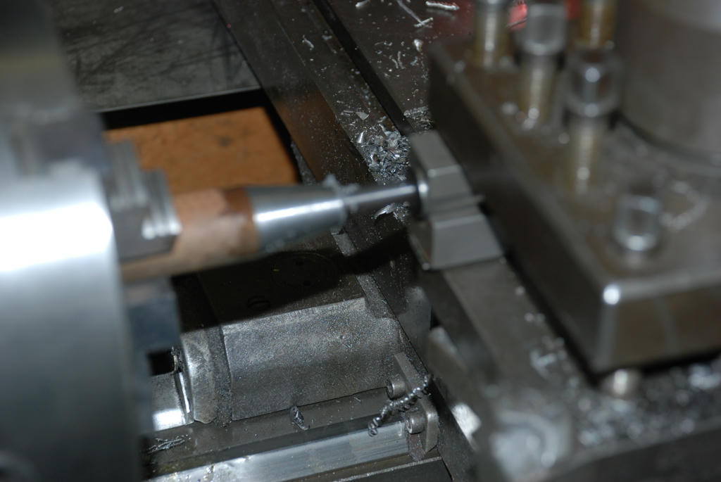
It’s been a while since I have been able to work on the Epoxy Worden grinder. After a lot of experimentation with the motor I have decided to make this first version in the same way as the original, with the motor mounted in the center of the base in a fixed position. As mentioned previously I would like to experiment with a motor and separate spindle that is adjustable. When I find the right motor (It needs to be small and powerful) I will make another grinding head. The new metric motor I purchased turned out to have a tapped hole, (M4) about 16mm deep in the end of the 14mm shaft, the motor shaft also has a small step after the 30mm long by 14mm diameter shaft mounting section….Perfect, this was a lucky find. Surprising to me the motor had little axial play it appears there must be some preloading. Time will tell if this remains or some looseness develops. I guess that can be addressed if need be in the future. I also had to hand a small grinding wheel adaptor for 1.25 inch bore grinding wheels; it has a tapered bore to enable it to be accurately centered on a tapered spindle. I believe it was originally designed to fit a Cincinnati number 2 tool and cutter grinder, Another find at a market. When I have the time I will make several more in a batch I already have another spindle I made up that was used to grind the lathe bed that used this adaptor. By having each wheel in its own adaptor should mean that you do not have to re-dress the wheel when it is fitted. After some effort I found this site where you can purchase ready made similar but not exactly the same wheel adaptors however they are not inexpensive, and will not be that hard to make up a batch of your own. http://www.wmsopko.com/catalog.php3?pagelist=31-32-33-34-35-36-37-38-39-40-41-42-43-44-45-46-47-48-49-50-51 As the following photos show I was able to make a small tapered cone that fitted over the motor shaft up against the step. It was turned on the lathe in one setting. Using the following sequence; first the taper was turned using the top slide, after a few cuts and by carefully tapping the top slide with the clamp bolts loosened I was able to get a good match to the grinding wheel adapter taper. I used a (thin) smear of Windsor and Newton artists Prussian blue oil paint to test the fit of the taper, in the end there was an even shade of blue, if you don’t have a good fit one end will be darker than the other.
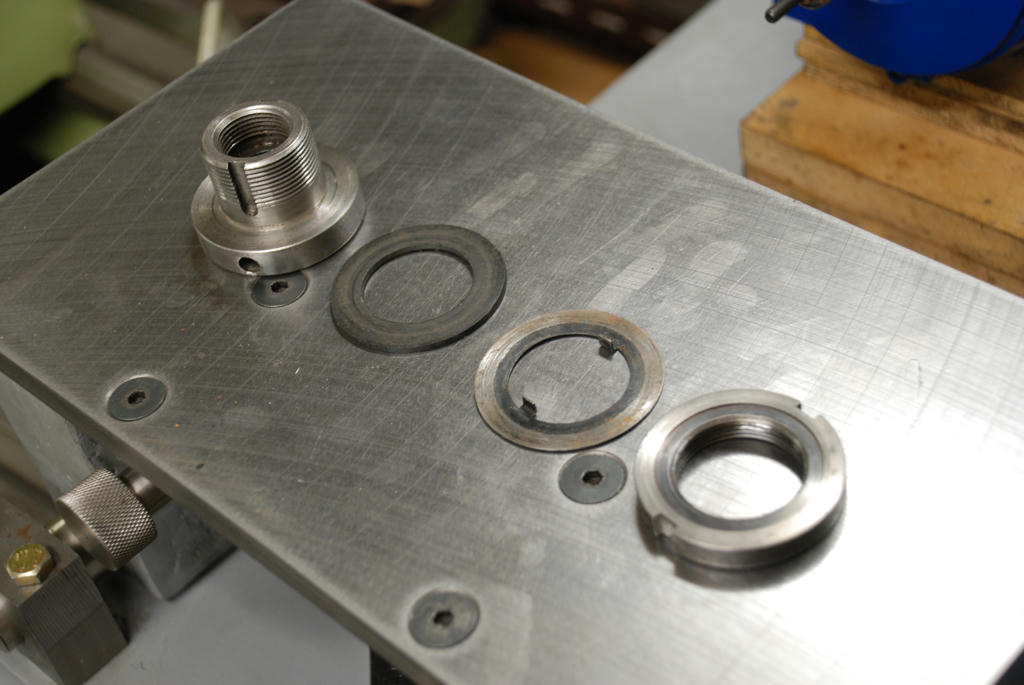
Then the shaft was drilled 12mm and bored out to 14mm. I used a snap gauge to measure the bore and a micrometer set to the motor shaft diameter (which was slightly undersize) to test the bore against the motor shaft, snap gauges are very useful allowing you to test the size of the inside of the bore along its length, Far more accurate than a caliper, a good result there…. a medium push fit on the motor. Once the bore was done the previously turned taper was skimmed lightly again to correct any possible errors introduced by the drilling and boring. Then the cone was parted off and placed in the wheel adaptor and tapped home with a soft hammer this allowed the adapter with the cone in position to be placed in the lathe chuck and gently faced off. The cone did not come loose while doing this. An M4 high tensile bolt while quite adequate to retain the wheel adaptor has a fine thread, I am concerned that the thread will wear in the motor shaft with use I therefore chose to use the threaded portion cut from an m4 high tensile bolt as a stud and having screwed that into the motor shaft, locked it in place with a nut. If the stud wears with use it can be replaced the motor shaft thread has been protected. The wheel adaptor itself will be retained with another nut on the stud (Not shown in the photo). This method has allowed the grinding wheel to be fitted very close to the motor with little overhang, tightening the mounting bolt will compress the adaptor harder onto the shaft. There was no need to split the adaptor with a light press fit. When I tested it there was no visible wobble or movement of the grinding adaptor, the advantage of machining the inside and outside of the piece in one chuck setting, and little vibration, a very satisfactory result. In Hindsight a three phase motor would have been a little smoother. Single phase motors are never quite a good in that regard. The next step will be the motor mounting pad then the table and graduated dials. Hopefully I will have a little more time over the next week or two, It will be great to finish this project. And test the results. Cheers John Boring the adaptor (Opologies re out of focus.)
 After the taper was given light skim it was parted off 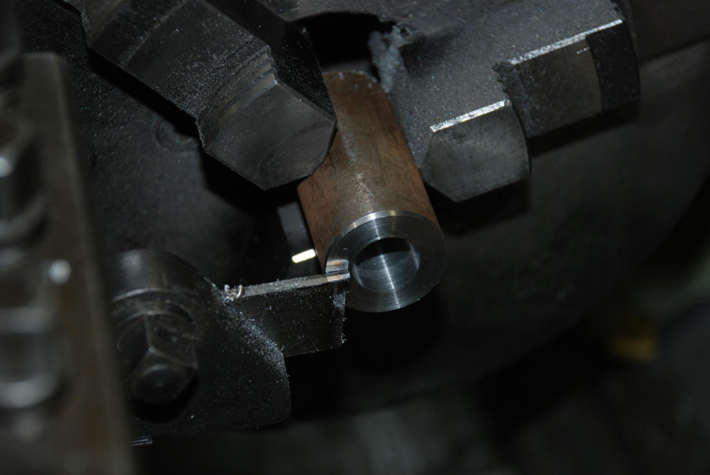 Continued next post.... Edited By John McNamara on 28/07/2011 14:41:32 |
| John McNamara | 28/07/2011 14:56:48 |
1377 forum posts 133 photos | Continued from previous post....
Adapter ready to install
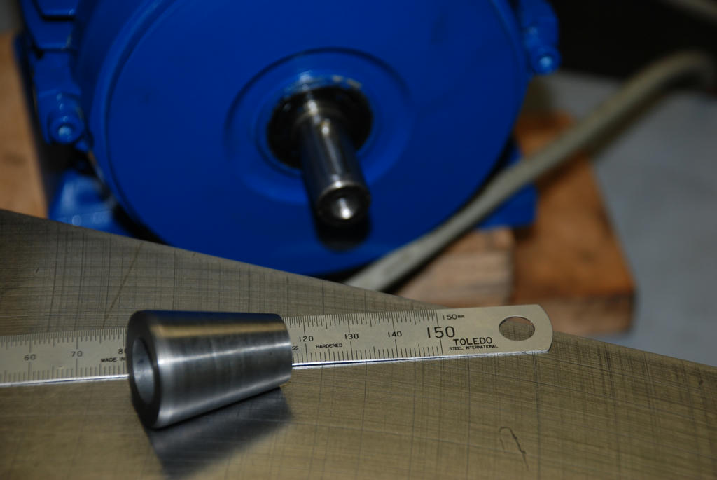 Adaptor and M4 Stud fitted on shaft 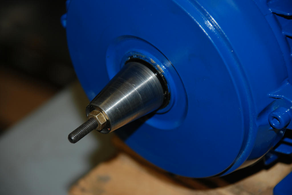 With wheel in position little overhang. 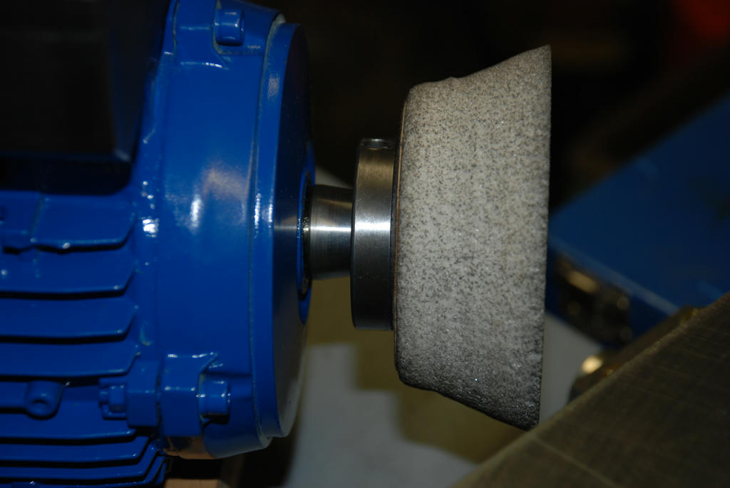 Components of adaptor: Body (milled slots are to engage lugged washer, to allow the motor to be reversed without turning the mounting nut off.) Rubber washer. (Grinding wheels should not be mounted rigidly)
Locking nut.
 Motor specification 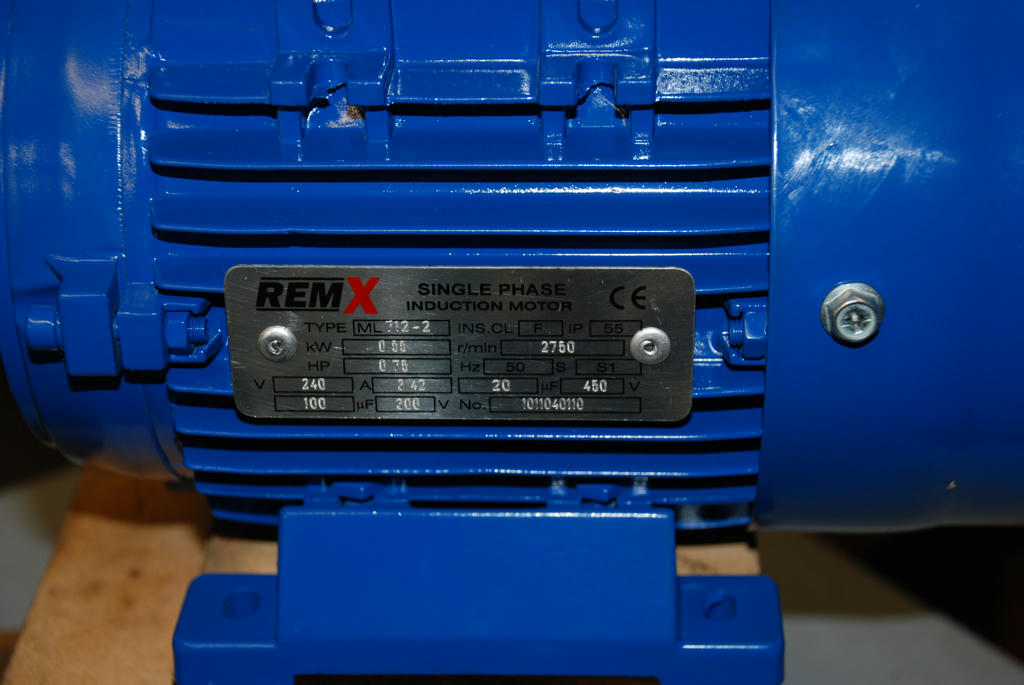 Link to High resolution images (There are a few more than shown)
Cheers
John Edited By John McNamara on 28/07/2011 15:22:37 |
| Richard Parsons | 28/07/2011 18:01:25 |
 645 forum posts 33 photos | Mike If you can drop your ‘hooks’ on an old spin dryer motor. The ones with brushes all you need is the bearing head set (2 Tangential ball races or 2 cone rollers). Make the pulleys to suite the elastic belting used in some washing machines. A cheapo fan controller kit –the pulsed DC type-(to give you variable speed) and away you go. The spin drier motors run up to about 12,000 RPM higher with no load so watch it when you are testing them (I had one Russian motor burst its ‘commutator’ before it ran up to ‘windage’ the fan on it was slipping) I will post some Pics later Regards Dick |
| John McNamara | 29/07/2011 01:31:29 |
1377 forum posts 133 photos | Gee Richard
The control system would have to be (fail safe). 12000 rpm would explode nearly all 100mm grinding wheels. Not easy to guarantee if the speed control shorts out. Not an uncommon failure mode.
Cheers
John |
| Richard Parsons | 29/07/2011 14:02:33 |
645 forum posts 33 photos | The spin drier motors will only run up to 12,000 rpm or there abouts if they are under no load conditions if it has no fan.. The spin drier motor I use came from an old Electrolux and used a belt drive. In No load conditions the cooling fan prevented running up to about 5000 RPM. The Russian motor had no fan and went into runaway!
The speed controler is a very ancient design. I think if any part of it gets 'curried' the whole thing it goes 'Open Circuit'. I will 'open the box and copy the circuit. |
| Gray62 | 30/07/2011 00:38:31 |
| 1058 forum posts 16 photos | When is somebody going to take the time to fix this forum so that the adverts do not overlap the text in the posts. It should not matter what is posted in the text, that should not have any effect on the formatting of the forum. If this is a long term problem then the publishers should be considering changing the software application used to provision the forum. After all, the facilities provided are pretty basic compared to other ME forums on the web. |
| John McNamara | 30/07/2011 01:35:03 |
1377 forum posts 133 photos | Hi All
I neglected to state the angle of the grinding wheel adaptor. As used by Cincinnati it is 4.5 inches per foot. As shown in the site link posted in my previous post. In degrees this is an included angle of 20.5560 deg. Meaning the top slide has to be set to an angle of 10.278 degrees relative to the work. The adaptor I have has an overall diameter of 50mm. If anyone wants a drawing. I will be pleased to email one. When the project is finished I will post a full set for the entire machine. Cheers John |
| D Squire | 30/07/2011 02:53:00 |
| 6 forum posts | To someone that cares What is the reason for not being able to see the last several words in every line in most of the posts? If I have to guess at what is being said then I probably won't be coming back too often as I like the whole story, not 3/4's of it. Cheers Don |
| John McNamara | 30/07/2011 06:11:51 |
1377 forum posts 133 photos | Hi All
I have observed that posting a Microsoft word document into the “Post a reply” edit box, the “paste from word” button, causes the right hand advertisement boxes on the forum to overlay the forum user text window. This is clearly a bug in the webpage design. However until it is fixed if you use the clipboard to select text in word then paste it using the “Paste plain text” Button (NOT) the “paste from word” button the problem will not arise. I use internet explorer and windows 7 there may be different results from other web tools. Cheers John  Edited By John McNamara on 30/07/2011 06:12:36 |
| John McNamara | 07/08/2011 15:15:06 |
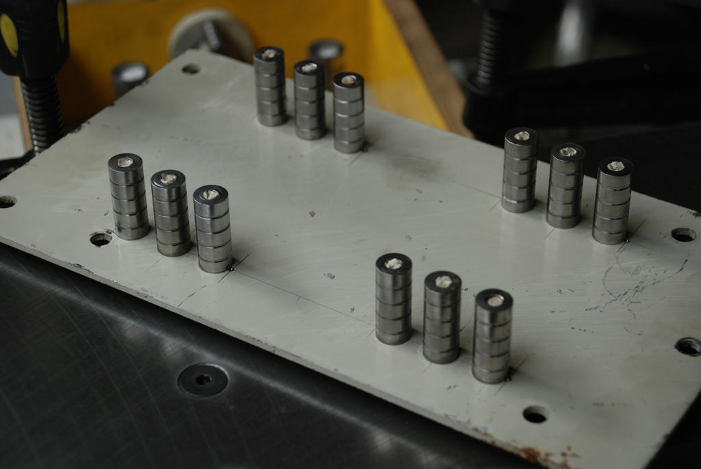
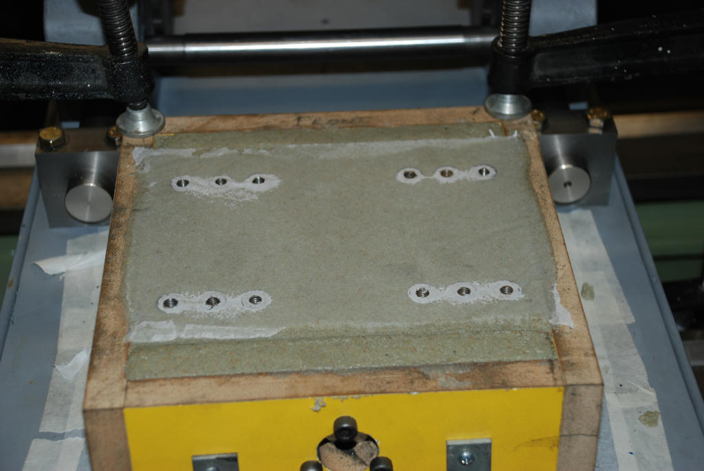
1377 forum posts 133 photos | Hi All At last some time to do some interesting work on the Epoxy Worden Grinder. The motor mounting base has been poured; tomorrow it will be ready to strike from the mould and after a tidy up if the sharp edges and any blemishes will be ready to use. This is the most complex casting so far, as the illustrations show it has 4 steel bushes turned, and grooved (I used a parting tool) from 18mm black mild steel drilled and counterbored for M8 hex cap screws to attach it to the base. The motor mounting block is cast on top of the base in situ; the bushes were tightened securely to the base using the existing holes prior to casting. A perfect bearing has resulted. Note the location of the mounting bushes is not ideal; I changed the design making the mounting block larger to allow the different to originally chosen motor mounting point. However with 4 M8 high tensile bolts holding the motor mounting block it will be an extremely strong connection. I will relocate the bolts in the final plan for aesthetics. For others building this machine it is easy to relocate the inserts for motor mounting I also provided for the motor to be shifted off centre left and right. In practice the left or right edge of the wheel is used. I suspect the best position is actually off centre not as in the original Worden design. The Epoxy worden also has a micro adjustable XY table for further adjustment. The motor mounting cast in inserts made from 12mm mild steel rod turned, grooved and tapped M6 to match the motor base, can be seen mounted on a piece of scrap metal. Accurately located and drilled, this plate will be plunged into the mould after the Epoxy casting material is placed, I had not done this before and was concerned there may be a less than perfect cast around the inserts, I planed to strip the steel as soon as the epoxy was set “Green” so that a patch could be done while the epoxy was still green if need be. It did not prove necessary to patch but I will continue to do this in future casting as you cannot see under the plate. You could use Perspex but that is expensive unless you are making a number of parts. In the centre of the motor base can be seen a steel part, this houses the pre loaded nuts for the y axis feed. Made from a piece of 1 inch by 1/8 inch seamless mild steel tube, from the scrap bin, inserted at the front end is an 80mm long steel insert threaded M12x1.5 (I had to extend the tap it was too short) this was made to a light press fit (I also pinned it just in case) At the rear another 80mm insert threaded M12x1.5 this time a sliding fit and at one end. A small shoulder was turned to locate a press fitted a disk about 50mm diameter by 8mm thick up against it. The disk has 3x5mm holes for the M5 Cap screws that screw into the threaded inserts made from scrap to be cast in. This part can be seen in the photos it is wrapped in 4 layers of masking tape to provide clearance around the edge and to stop it from being stuck to the epoxy (This part has to move to allow adjustment of the preload), only the inserts are visible. I also had to relieve the 25mm tube slightly to clear the inserts. Interestingly I had planned to simply cast in the inserts and the disk part would have sat proud of the motor base. I am still trying to clear my head of thinking as a metal designer. The recess would be a time waster machining it. Casting removes the constraint 5 minutes masking it and the job was done. The part will look better and it will keep dust out. The front end of this part sits directly under the grinding wheel; it would not be good for the nicely greased preloaded clearance thread to be bathed in dust. The 20mm projection will allow the attachment of a sliding shroud to keep dust out. By using 2 rather long 80mm nuts any cyclical errors in the roll formed threaded rod tend to be evened out. A smooth and extremely rigid action resulted. I am very pleased with the fit and will use this method again. Moulding Hints: As can be seen the mould itself is just 4 small pieces of melamine MDF scrap screwed together with bugle head drywall screws, I do not use glue, It is important to drill the screw mounting holes to clear the screw and the end grain attachment point slightly smaller than the screw, about 1.5mm less, if this is not done the end grain will split. The mould inside was coated with a little grease to stop the epoxy sticking. I used a sheet of “kitchen baking sheet” a kind of waxed Paper also greased to protect the base. I also wrapped the steel plate that holds the motor mount casting inserts in the same paper to stop it sticking. For this batch I used the following Epoxy / Mineral casting mix. Fine washed sand 70 percent, Megapoxy HICB 30 percent to make a total of 2.66 litres of mix. HICB is normally used in rock crushers to mount the hard facings; it is made from about 65% silica powder and the balance epoxy. Therefore the actual amount of epoxy used in this part is around 14% by volume the rest being sand and silica powder. The quantities worked out fairly well with less than a cup left over I used it to make a small sample. The cup I think it contained yogurt was made from polypropylene; epoxy does not stick to it. Note the high surface finish when it was turned out. If I was using straight epoxy I would have used a similar amount around 14% of epoxy the balance 86% being sand and silica powder if available. The material was mixed for about 15 minutes by hand; hard work as it is quite stiff and very necessary. Continued next post........ Edited By John McNamara on 07/08/2011 15:17:54 |
| John McNamara | 07/08/2011 15:19:00 |
1377 forum posts 133 photos | Continued from previous post.........
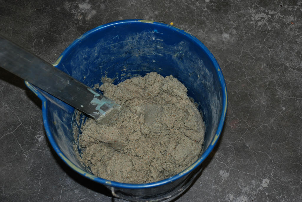
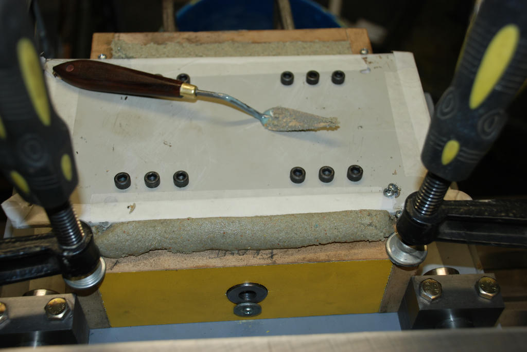
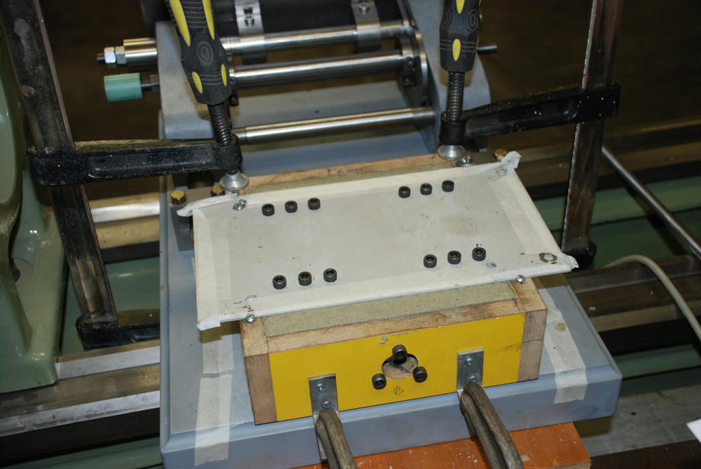
Note the consistency of the epoxy in the photos; as you can see in the bucket the mix is a “friable” “boney” if you are a concreter, mass it is does not slump much of its own accord. As shown the mould was filled in three steps firmly rammed between each step with a small steel bar on end, angling the blows to direct material under any objects above and very well around all edges and corners. After the second step the material sat a little below the top of the mould. This surface was filled again then rolled and leveled off. Then the upper mounting inserts were pressed into the mould and the plate that holds them was screwed down, then wrapped all over with a hammer to vibrate the mould, the material that was displaced by the mounting inserts and squeezed out the sides was rammed from both sides to help consolidate the mould and to avoid voids then trimmed off. As the photo shows after stripping there was a pretty good result.
If was doing this again I would have a hole in the centre of the steel plate, to enable the last bit material to be rammed in and completely cover the top of the formwork (but leaving a 2mm gap between them), then only the centre hole area and the 2mm sprue around the edge would need to be cleaned up after the mould is stripped. As done in the example there will be a bit of wet grinding with a rough oilstone to level the top, it is times like this I wish I had a surface grinder. It looks like I have to remove about 1.5mm on average to remove the high spots. It is also planned to arris all edges with a disk grinder. The epoxy material is fairly clean to work with; rubber gloves are a good idea as it is hard to get off your hands and some people may be allergic. If you do get it on your hands and to clean your tools turpentine and mentholated spirit (Mixed on a rag will clean it off quickly.) The mix works better than one solvent alone. (No safe to use or available chemical solvent will remove epoxy that has set) Altogether a pleasant day’s work, I will not strip the rest of the formwork for the next 24 hours. The next step is to make the bracket to join the Y axis feed to the carriage, and then finally the table slot and mounting points and the knobs and handle. I will post a photo of the motor in position in a day or two. Cheers John Formwork clamped in place, Base mounting inserts in position, Y axis preloaded nut assembly installed.
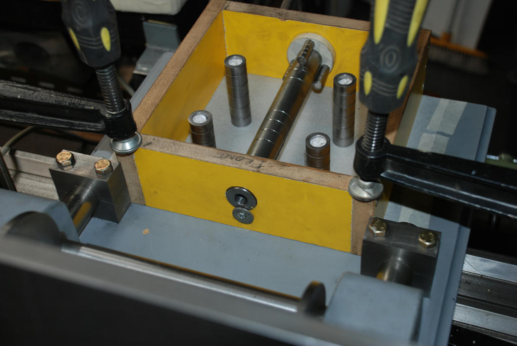 Motor mounting inserts on alignment plate
 Mix is a friable stiff mass
 First layer ready to tamp 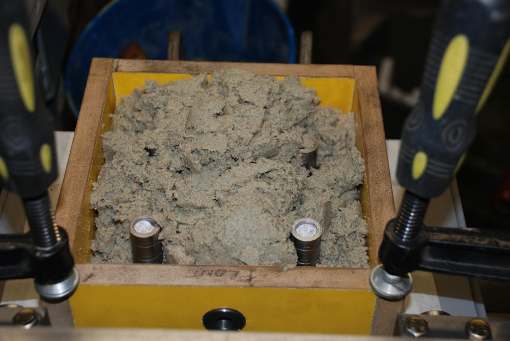 First tamping started 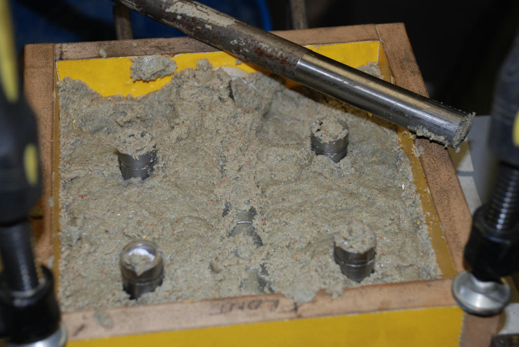 Second layer tamped 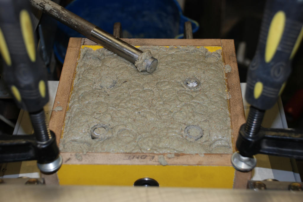 Rolled off level 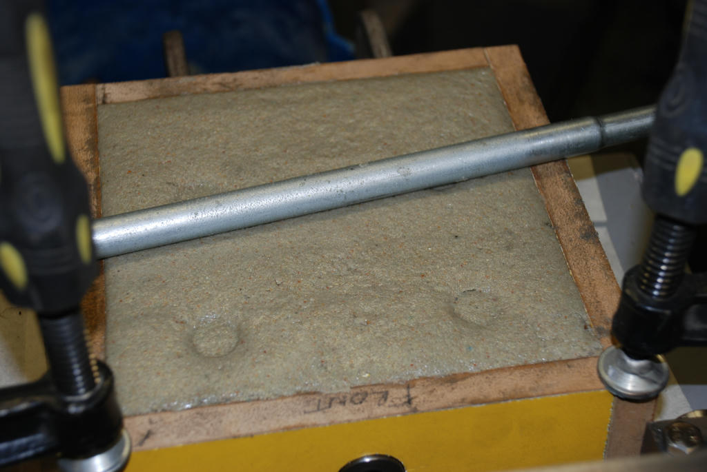 Motor mounting inserts placed
 Waiting to cure
 Continued next Post....... Edited By John McNamara on 07/08/2011 15:46:00 |
| John McNamara | 07/08/2011 15:52:24 |
1377 forum posts 133 photos | Continued from previous post......
Motor mounting insert alignment plate stripped.
A little grinding to level it off and arris the edges and the casting is finished.
 A small sample made from left overs... Note the high surface finish the cup was polypropylene epoxy does not stick to it. 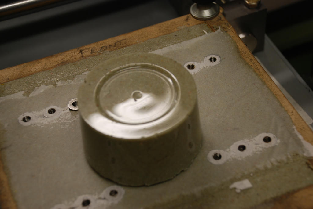 Cheers John Edited By John McNamara on 07/08/2011 15:53:43 |
| John McNamara | 07/08/2011 16:25:57 |
1377 forum posts 133 photos | Hi All
A link to all the images (And a few more) taken for this stage of the project
At high resolution.
Cheers
John
|
| John McNamara | 08/08/2011 15:38:02 |
1377 forum posts 133 photos | Hi All
I learnt something today….You can machine sand/silica based epoxy castings with metal inserts! As noted in the previous post there was a need to clean up the casting top, about 1.5mm needed to be trimmed of the top to level it (See the notes in the previous posts to avoid this happening). My first plan was to stone the top using a rough silicon carbide stone I know this works, but it was going to be slow. I kept thinking there must be a better way; about that time I remembered an old cutter I got with a mill drill I purchased many years ago. A photo is attached. I was never very happy with this cutter as it tended to produce a rough finish on steel. Luckily I had a 3 Morse taper to 40 int taper adaptor so I could use it in my new 30 year old mill. As the picture shows it uses removable carbide tipped tool bars. Although a couple of the tips were chipped I though it would be no loss to give it a try. I assumed a slow cutting speed would be best and set the spindle speed to 75rpm and the feed to 2.9 inches per minute (The mill is imperial not metric) I did try to increase the cutting speed but the result was a rougher finish. Also when the cutter hit the inserts you have to imagine what is actually happening, the cutting edge of the carbide is covered with grit and you are asking it to cut steel. The result was not very pretty. The motor mounting inserts as luck would have it were made from a scrap of rather “Gummy” Steel. And were smeared as well as cut, I had to drill and re-tap them. Surprisingly the larger inserts for the base mounting bolts cut far more cleanly. I also wondered if the cutter would hold up or would need resharpening during the job, it held up OK. Yes it does need a resharpen but it did before I started…… And I know of a fantastic grinder to do it coming up. The picture attached is after the job was done. After milling the top the formwork around the sides was removed. That was not as easy as the other castings because this time I rammed the epoxy very hard and in doing so must have partly removed the grease I had used as a release agent. Not the end of the world but 20 minutes wasted chiseling the formwork off. And I managed to chip an edge note the patch. After that a lick with a small angle grinder with a flat flap wheel did a good job of rounding the edges and tidying up the patch. I gave it a quick spray with etch primer. When the machine is finished I will disassemble and paint the machine properly. As you can see the motor is now mounted in position, also the y axis feed screw is installed. The next step is the Y axis bracket and the table movements will be complete. Cheers John You can Mill Epoxy silica/Sand Mix. (No aggregate)
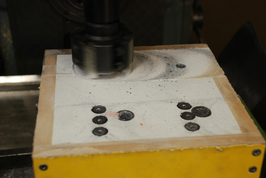 Formwork Stripped 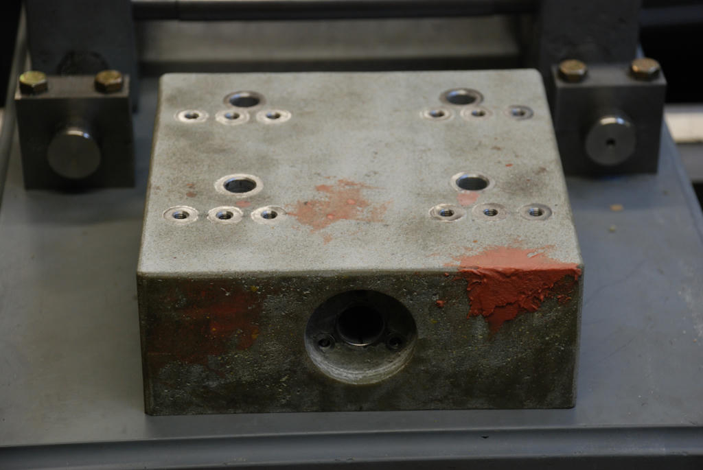 Motor and base and feed screw installed 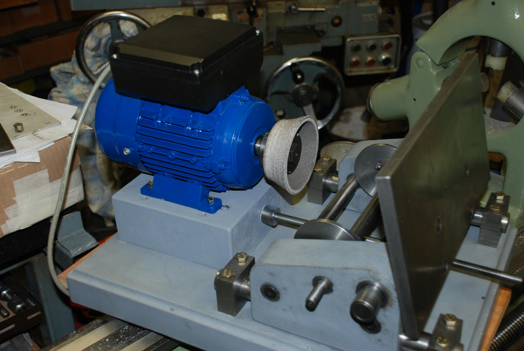 Taking shape at last 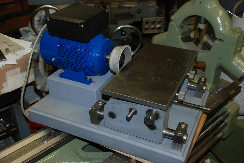 Cutter after milling Epoxy sand still OK but it needs a sharpen. Edited By John McNamara on 08/08/2011 15:38:51 |
| Springbok | 12/11/2011 06:19:08 |
 879 forum posts 34 photos | John
I have only just come across this thread but found it one of the best that I have ever read. I realise your last posting was august but did you complete the project It would be great to see it in print.
A lot of food for thought.
kind regards
Bob |
| John McNamara | 12/11/2011 07:10:00 |
1377 forum posts 133 photos | Hi Bob
Thank you for your words of encouragement.
I am still at my post! It is almost complete. I built the x and y feeds and they are both working.
All that remains is to disassemble, fine fit and repolish all the parts. sand back the grey primer and finish paint and it is almost done. A mate is going or CNC engrave the table for me.
I have actually been using it in its current state to grind lathe tools. I got a very fine finish. there is very little vibration.
I will post the result fairly soon.....Hopefully my current workload will reduce.
The workshop has had to take second place to work. however I am musing over a new project. It is a Machine made from standard RHS steel for guide ways. Clearly they are not accurate (Commercially about 1mm per foot curvature error among many other errors)
To counter this I plan to build a "Metrology frame" using Piano wire and use the wires as a reference for the CNC control.
The Concept is this; Before we had Computers and indeed for most of the population Electricity, Engineers had only basic measuring tools...Most work was done with a straight edge, square, ruler, geometry instruments, level and plumb bob. for longer distances the water level and, together with surveyors instruments. and naturally a string (Wire) Line.
For high accuracy "scraping" and other hand finishing requiring great skill enabled remarkable results was done by truly great craftsmen. Scraping allowed the rough machined surfaces to be refined.
A good example of state of the art at the turn of the last century is the war ship built In 1906 "HMS Dreadnought" Easy to find on Google.
My concept is to use basic CNC and a basic sensor design that senses the wire and using that as a reference guides a small cutting head to remove a small spot. repeated many times. The initial design is to generate flat surfaces up to 2000mm long and 400mm wide. (The machine is Vertical so no catenary sag of the wire although if flat it can be calculated out).
The tech nerds among us and I have to warn you I am one also. will yell Laser. Yes that is possible but not on a small budget. in fact not even for a largish budget.
Going back to the pre electronics era they did get results using wire. and remarkable results at that, as a visit to the Science Museum in London on line or in person will attest.
I have been thinking on this for some time the post I made below at another place a while ago has a number of links re wire alignment. It is still widely used..
Cheers
John Edited By John McNamara on 12/11/2011 07:25:51 |

Please login to post a reply.
Magazine Locator
Want the latest issue of Model Engineer or Model Engineers' Workshop? Use our magazine locator links to find your nearest stockist!
Sign up to our Newsletter
Sign up to our newsletter and get a free digital issue.
You can unsubscribe at anytime. View our privacy policy at www.mortons.co.uk/privacy
Latest Forum Posts
- *Oct 2023: FORUM MIGRATION TIMELINE*
05/10/2023 07:57:11 - Making ER11 collet chuck
05/10/2023 07:56:24 - What did you do today? 2023
05/10/2023 07:25:01 - Orrery
05/10/2023 06:00:41 - Wera hand-tools
05/10/2023 05:47:07 - New member
05/10/2023 04:40:11 - Problems with external pot on at1 vfd
05/10/2023 00:06:32 - Drain plug
04/10/2023 23:36:17 - digi phase converter for 10 machines.....
04/10/2023 23:13:48 - Winter Storage Of Locomotives
04/10/2023 21:02:11 - More Latest Posts...
- View All Topics
Support Our Partners


Shopping Partners
Subscription Offer

Latest "For Sale" Ads
- Reeves** - Rebuilt Royal Scot by Martin Evans
by John Broughton
£300.00 - BRITANNIA 5" GAUGE James Perrier
by Jon Seabright 1
£2,500.00 - Drill Grinder - for restoration
by Nigel Graham 2
£0.00 - WARCO WM18 MILLING MACHINE
by Alex Chudley
£1,200.00 - MYFORD SUPER 7 LATHE
by Alex Chudley
£2,000.00 - More "For Sale" Ads...
Latest "Wanted" Ads
- D1-3 backplate
by Michael Horley
Price Not Specified - fixed steady for a Colchester bantam mark1 800
by George Jervis
Price Not Specified - lbsc pansy
by JACK SIDEBOTHAM
Price Not Specified - Pratt Burnerd multifit chuck key.
by Tim Riome
Price Not Specified - BANDSAW BLADE WELDER
by HUGH
Price Not Specified - More "Wanted" Ads...
Get In Touch!
Do you want to contact the Model Engineer and Model Engineers' Workshop team?
You can contact us by phone, mail or email about the magazines including becoming a contributor, submitting reader's letters or making queries about articles. You can also get in touch about this website, advertising or other general issues.
Click THIS LINK for full contact details.
For subscription issues please see THIS LINK.
Digital Back Issues


Donate

 Register
 Log-in
Model Engineer Magazine
- Percival Marshall
- M.E. History
- LittleLEC
- M.E. Clock

ME Workshop
- An Adcock
- & Shipley
- Horizontal
- Mill

Subscribe Now
- Great savings
- Delivered to your door

Pre-order your copy!
- Delivered to your doorstep!
- Free UK delivery!
All Forum Topics > Model Engineers' Workshop. > New technology in Model Engineers Workshop