Forum sponsored by:

Home Made Rear Toolpost Issue
| Dr_GMJN | 09/03/2021 00:13:03 |
 1602 forum posts | Posted by Hopper on 08/03/2021 23:00:44:
PS I found this type of 5/16 x 1/16 (or 8mm x 1.5mm) parting tool holder works better than the side mount types. Holds the blade more verttical and does not move. Its all I use for general parting of small jobs. Less faff than fitting the rear post.
Thanks Hopper. I only fished out the rear post because I heard it was a much better method for parting. Sparey seemed to think they were invaluable according to the two books I’ve got. Anyway I’ve fished it out of the bin. Got this far, and I hate giving up. Another lost evening wont make any difference I guess. By the way - since you’re here... I fitted my new chuck (which is a bigger improvement than expected in terms of solidity and feel - the old one rattled!). I have noticed that I’m getting more measured movement of the nose bearing. It’s not a rattle, or play, more of a deflection, presumably exaggerated by the lever effect of the longer new chuck. The bearings have their original peelable surfaces. To make them more solid can I just peel off a thou each side and hope it doesn’t bind, or do I need to scrape the bearings (I’d leave well alone in that case). The oil feeds do drain quite quickly these days too, with more oil flung onto the floor than a few years ago. Or maybe I’m just using it more... |
| Hopper | 09/03/2021 05:10:14 |
 7881 forum posts 397 photos | Posted by Dr_GMJN on 09/03/2021 00:13:03:
Posted by Hopper on 08/03/2021 23:00:44:
PS I found this type of 5/16 x 1/16 (or 8mm x 1.5mm) parting tool holder works better than the side mount types. Holds the blade more verttical and does not move. Its all I use for general parting of small jobs. Less faff than fitting the rear post.
Thanks Hopper. I only fished out the rear post because I heard it was a much better method for parting. Sparey seemed to think they were invaluable according to the two books I’ve got. Anyway I’ve fished it out of the bin. Got this far, and I hate giving up. Another lost evening wont make any difference I guess. By the way - since you’re here... I fitted my new chuck (which is a bigger improvement than expected in terms of solidity and feel - the old one rattled!). I have noticed that I’m getting more measured movement of the nose bearing. It’s not a rattle, or play, more of a deflection, presumably exaggerated by the lever effect of the longer new chuck. The bearings have their original peelable surfaces. To make them more solid can I just peel off a thou each side and hope it doesn’t bind, or do I need to scrape the bearings (I’d leave well alone in that case). The oil feeds do drain quite quickly these days too, with more oil flung onto the floor than a few years ago. Or maybe I’m just using it more... Yes the rear tool post is well worth pursuing. Sounds like you have the best idea with bolting a slab of steel on top of your machined down cast iron. With such little wear or movement as you seem to have in your headstock bearings, scraping should not be needed. You need to measure exactly how much spindle movement you have by putting your dial indicator to bear directly on the spindle in the small gap between chuck and headstock bearing. Then hold a piece of bar about a foot long in the chuck and gently push it back and forth and up and down and measure how much actual spindle movement there is. Most wear and thus most movement will be in the 1 to 2 o'clock position when viewing the chuck from the tailstock end of the bed. Ideally you want quarter to half a thou or even less, with no drag. Anything more than a thou and you should be looking at pulling out a shim. I'm not sure how thick each layer is on the factory shims because I cut my own shims from shim stock. I think the factory laminated shims might be about two thou each layer? But not sure. Never measured them. You can cheat a little bit and take a layer out from one side but not the other so you get a more or less half-a-shim thickness adjustment. Purists will doubtless be at the gate with torches and pitchforks shortly but the difference is so little it does not negatively affect things. Another thing you can try before that is to try tightening down the two allen screws that hold the bearing caps down with a short piece of pipe over the allen key to about double the length of leverage. Be careful not to strip threads of course but you can reduce clearance by up to half a thou that way as wonky shims are compressed and oil forced out of gaps etc. YOu should check those screws before doing the dial indicator test anyway as they can come loose over the years of vibration. Likewise, if you peel off a layer and find the bearings just a tad too tight, you can back off those allen screws a tad so they are still tight but not maximum tight and get back a quarter to half a thou of clearance. OIl consumption does not say much about bearing wear on these because the bearings include honking great X grooves carved into them that lead oil almost to the edge of the bearing from whence oil will make the final leap to freedom regardless. That's why I use 20/50 motorbike oil in mine. I find the "proper" ISO 32 or even 46 too thin and hard to control the flow down to the two drips a minute I aim for. My pet hate on Myfords is the total loss oil system mess. So 1936. |
| Dr_GMJN | 09/03/2021 08:11:29 |
1602 forum posts | OK thanks Hopper, I'll re-evaluate when I've finished the toolpost and handwheel. I suppose at least the total loss oil system flushes out any crap in the bearings, and doesn't get recirculated. My oilers seem to go from zero to full flow in about 1/100 of a turn.
|
| Dr_GMJN | 03/04/2021 16:58:03 |
1602 forum posts | Posted by Hopper on 09/03/2021 05:10:14:
Posted by Dr_GMJN on 09/03/2021 00:13:03:
Posted by Hopper on 08/03/2021 23:00:44:
PS I found this type of 5/16 x 1/16 (or 8mm x 1.5mm) parting tool holder works better than the side mount types. Holds the blade more verttical and does not move. Its all I use for general parting of small jobs. Less faff than fitting the rear post.
Thanks Hopper. I only fished out the rear post because I heard it was a much better method for parting. Sparey seemed to think they were invaluable according to the two books I’ve got. Anyway I’ve fished it out of the bin. Got this far, and I hate giving up. Another lost evening wont make any difference I guess. By the way - since you’re here... I fitted my new chuck (which is a bigger improvement than expected in terms of solidity and feel - the old one rattled!). I have noticed that I’m getting more measured movement of the nose bearing. It’s not a rattle, or play, more of a deflection, presumably exaggerated by the lever effect of the longer new chuck. The bearings have their original peelable surfaces. To make them more solid can I just peel off a thou each side and hope it doesn’t bind, or do I need to scrape the bearings (I’d leave well alone in that case). The oil feeds do drain quite quickly these days too, with more oil flung onto the floor than a few years ago. Or maybe I’m just using it more... Yes the rear tool post is well worth pursuing. Sounds like you have the best idea with bolting a slab of steel on top of your machined down cast iron. With such little wear or movement as you seem to have in your headstock bearings, scraping should not be needed. You need to measure exactly how much spindle movement you have by putting your dial indicator to bear directly on the spindle in the small gap between chuck and headstock bearing. Then hold a piece of bar about a foot long in the chuck and gently push it back and forth and up and down and measure how much actual spindle movement there is. Most wear and thus most movement will be in the 1 to 2 o'clock position when viewing the chuck from the tailstock end of the bed. Ideally you want quarter to half a thou or even less, with no drag. Anything more than a thou and you should be looking at pulling out a shim. I'm not sure how thick each layer is on the factory shims because I cut my own shims from shim stock. I think the factory laminated shims might be about two thou each layer? But not sure. Never measured them. You can cheat a little bit and take a layer out from one side but not the other so you get a more or less half-a-shim thickness adjustment. Purists will doubtless be at the gate with torches and pitchforks shortly but the difference is so little it does not negatively affect things. Another thing you can try before that is to try tightening down the two allen screws that hold the bearing caps down with a short piece of pipe over the allen key to about double the length of leverage. Be careful not to strip threads of course but you can reduce clearance by up to half a thou that way as wonky shims are compressed and oil forced out of gaps etc. YOu should check those screws before doing the dial indicator test anyway as they can come loose over the years of vibration. Likewise, if you peel off a layer and find the bearings just a tad too tight, you can back off those allen screws a tad so they are still tight but not maximum tight and get back a quarter to half a thou of clearance. OIl consumption does not say much about bearing wear on these because the bearings include honking great X grooves carved into them that lead oil almost to the edge of the bearing from whence oil will make the final leap to freedom regardless. That's why I use 20/50 motorbike oil in mine. I find the "proper" ISO 32 or even 46 too thin and hard to control the flow down to the two drips a minute I aim for. My pet hate on Myfords is the total loss oil system mess. So 1936. So today I tried peeling off a 0.001" shim from the back of the front bearing block - the shaft locked on re-fitting, so I guess the amount of play can't be too bad. I suppose removing 0.001" from one side only gives a net 0.0005" closure of the bearing - approximately? Anyway I replaced the shim and it's back to how it was, so nothing lost. |
| Dr_GMJN | 03/04/2021 16:58:27 |
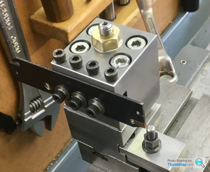
1602 forum posts | So I've repaired the rear toolpost as suggested with some S275 steel, and M8 capheads: |
| JasonB | 03/04/2021 17:06:48 |
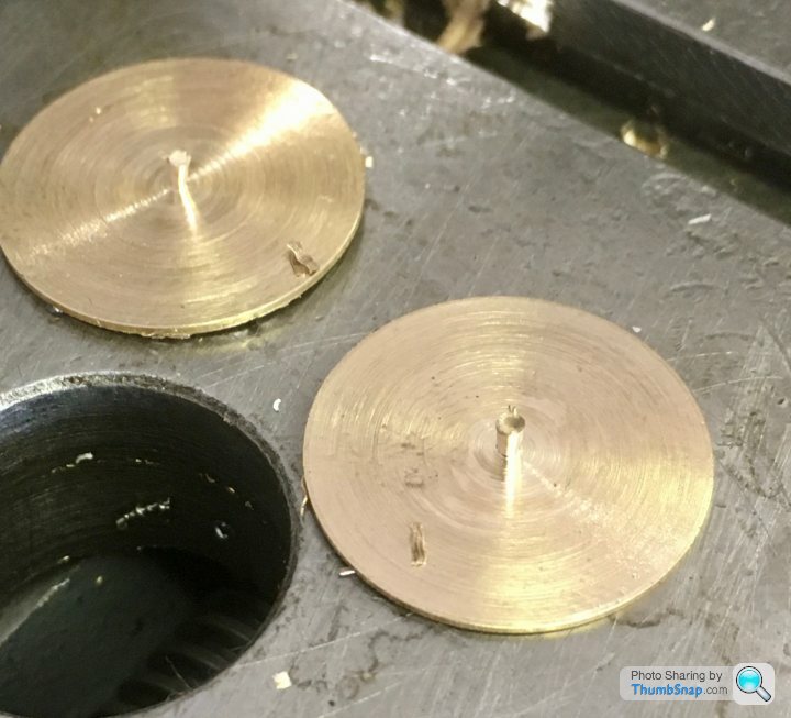
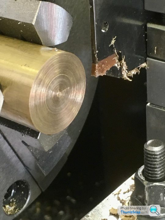
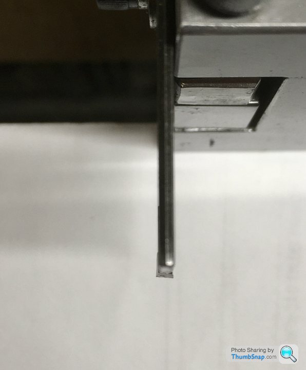
 25215 forum posts 3105 photos 1 articles | The pip is simply the brass shearing off as the small dia remaining can't resist the cutting loads. Does not look like you have an angled insert just the standard GTN where the N stands for neutral opposed to L&R which leave the pip on one side or the other Edited By JasonB on 03/04/2021 17:07:24 |
| not done it yet | 03/04/2021 18:02:42 |
| 7517 forum posts 20 photos | So all in all it works, but I wouldn't bother again - I'd just stick with the conventional front mount. Well, you are most certainly in the minority! But, as always, it’s your choice. |
| Dr_GMJN | 03/04/2021 19:51:01 |
1602 forum posts | Posted by JasonB on 03/04/2021 17:06:48:
The pip is simply the brass shearing off as the small dia remaining can't resist the cutting loads. Does not look like you have an angled insert just the standard GTN where the N stands for neutral opposed to L&R which leave the pip on one side or the other Edited By JasonB on 03/04/2021 17:07:24 This is a top view, I assumed the pip would be left on the part in the chuck with this geometry. I don't know the designation of the inserts - I've had them ages. |
| John Baron | 03/04/2021 20:05:12 |
 520 forum posts 194 photos | Posted by Dr_GMJN on 03/04/2021 16:58:27:
So I've repaired the rear toolpost as suggested with some S275 steel, and M8 capheads: Hi Dr GmJn, From looking at your pictures, you have made a very nice job of the repair on that tool post, I like the toe clamp. A good idea. However I wouldn't tighten the clamp screws down so hard as to distort the new tool holder cap plate ! Another point is that the parting blade extends outside the cross slide, the ideal position is to have the blade above the slideway of the cross slide. This will reduce the cutting forces that want to tip the tool holder towards the tailstock, reducing stability. My last suggestion is that the tool cutting edge is several thou too high. That pip is far too thick just for the overhang to break it off like that, the ideal is that the blade should be dead on centre height. JMTP.
|
| DMB | 03/04/2021 21:47:49 |
| 1585 forum posts 1 photos | Chronos "Spare Parting Blade Toolholder Myford Quick Change Toolpost", code SKU MFSP, £19.12incl. vat. Look that up, illustrates what I use in the front with a blade marked HSS 3/32 x 1/1 x 4 M2. It is not marked as being a Chronos tool but is identical. Had this for sometime and cannot remember source. Cannot trace anything like it on any other ME suppliers website, so have to assume it probably was from them.I used it recently to part off 7/8"D washers. Centre height is pre - set, just clamp to toolpost, slacken TP nut, run carriage towards stationary chuck and hold blade against front face of chuck then tighten TP nut. A drop of cutting oil, steady feed at half normal turning speed and swarf crinkles up in corrugation making a noise like frying bacon. No dog ins, cut as square as desired, no problem. Nice stiff blade, no bending resulting in concave and convex surfaces. Superb combo of blade and holder. Just satisfied customer of Chronos, nothing else.
|
| not done it yet | 03/04/2021 22:54:54 |
| 7517 forum posts 20 photos | I’ve never looked at the construction of my rear tool post - it was already fitted when I bought the lathe. It just works - I just turn on the power feed and watch it part off. All I have to be very careful about is ensuring the power feed does not run out of travel (something would break, operating in that direction). This only important with minimum cutter overhang as the tool post is set at the rear T-Slot on the cross slide. I’m not trying to be critical of the job but there are few better points with mine, viz: It has a flat base - I re-align it after shifting it (no great hassle) but it is relatively easily turned 90 degrees (for extra space) on occasions (complete removal from the lathe is a relatively rare event). The top securing nut has a handle, so facilitates this with ease. The second base fixing is by cap screw to a T-nut in the same slot as the main hold down. Presumably there is more than sufficient adjustment when re-aligning the tool post. That cap screw is not counter-bored, but is out of the way - I would suggest a suitable cap screw, counter-bored, in that toe clamp would look better than a stud sticking up (but the hex would fill with swarf). Certainly not an important change and won’t get in the way while cutting. Mine has cutter holder just like that shown by hopper (on page 5?). I just loosen the clamp and slide the blade in or out as required. The blade is simply removed and sharpened on a grinding belt when it gets dulled. I have a spare blade if/when this one wears away. Those clamping screws, for holding the cutter holder, reallyn need the threads removing at the ends - or they may spread and damage the female threads if removal is required in the future. Also those screws look quite marginal on length, although they are tightening just enough... I expect my actual tool post is made up of only two main parts, possibly shimmed apart, for original centre height adjustment (but likely surface ground when made?), along with the one machined slot (for that tool holder) plus associated holes and fixings. I am probably lucky in that, while I like to repair breakages, I do have a relatively abundant supply of larger sections of some materials. I wouldn’t have bothered to repair that one - the chunk would not have gone in the scrap bin, mind. But all good practise to find the limits of repairing things, I suppose. |
| DMB | 04/04/2021 09:01:06 |
| 1585 forum posts 1 photos | Small edit to my last posting yesterday re my very nice parting toolholder and blade. I missed a dimensional error of the blade, it should have read 3/32" x 1/2" x 4" |
| DMB | 04/04/2021 09:11:35 |
| 1585 forum posts 1 photos | I have an iron casting and drawing for the GHT design of rear TP. I am thinking how I can mod. the design to incorporate the style of clamp used in my topslide TP as detailed yesterday and add a simple alignment plate on the chuck side, together with 2 long Tee nuts to make them easier to insert into the slots. I would then not need to mill an alignment tenon. Another roundtoit about to be completed so I can write it up in my club's newsletter. |
| SillyOldDuffer | 04/04/2021 09:45:32 |
| 10668 forum posts 2415 photos | Posted by Dr_GMJN on 03/04/2021 16:58:27:
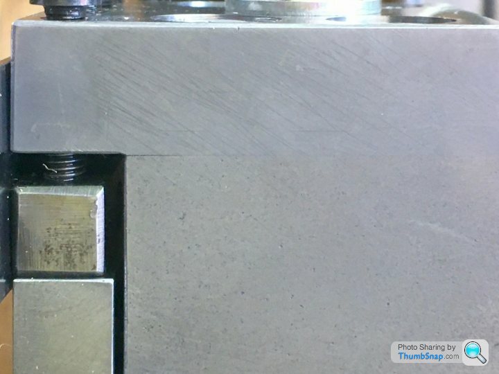
So I've repaired the rear toolpost as suggested with some S275 steel, and M8 capheads: Dare I suggest the good Doctor's conclusion is faulty without causing offence? Good attempt at a repair, and it deserved to be successful, but it isn't. The whole point of rear tool-posts is to improve rigidity, and that gap being able to open up means it's not rigid enough. This is a faulty rear tool-post, not a good one. Safer I feel to conclude this particular tool-post wasn't worth the trouble rather than assuming rear tool-posts in general don't work well: they do! I'm still wondering why the original broke? Fatigue failures are common at corners but many stress cycles are needed before they break, which seems unlikely. Possibly the metal was flawed, or maybe wrong for the job (cast iron?) Otherwise gross overtightening of the clamp bolts might do it - please confess if you believe nuts and bolts should be tightened with an extender and snugged up 'properly' with a hammer. (I knew an ex-Royal Engineer trained to hammer tighten hefty Bailey Bridge fixings, who couldn't stop shearing off the delicate RS232 retaining screws used in computer installations! Problem fixed by forbidding him to touch them.) We'll probably never know, but some microphotographs of the fracture would have been interesting, Dave
Edited By SillyOldDuffer on 04/04/2021 09:47:36 |
| Dr_GMJN | 04/04/2021 10:16:39 |
1602 forum posts | Thanks all - I’ll try the-positioning it more centrally, and try lowering the blade slightly. I’ll also remove some bolt thread. I’m not sure you can say it’s not rigid enough just based on a gap opening up. It’s almost inevitable that jacking a joint like that apart will result in a gap - theres not really enough room for wider headed bolts to get more clamp force. I would say that my conventional q/c tool holders will spring apart slightly, perhaps even more than the gap, but there is still a hell of a lot of residual stremgth there - remember it’s not a crack, it’s a deflection. |
| Howard Lewis | 04/04/2021 10:25:58 |
| 7227 forum posts 21 photos | S O D. The original broke because the cast iron was subjected to tensile loading, in which cast iron is weak. The gap is appearing because the screws clamping the tool holder are levering the end of the steel plate upwards, Possibly not enough to cause problems. Does it work as required? If Yes, live with it. If NO, why not vee the joint line all around and braze it. Hopefully, the braze will have enough tensile strength to plus the stiffness of the top plate, to prevent the clamp screws failing the braze. If the worst comes to the worst, make a new replica post, but out of steel. Parting off with a rear toolpost is better than with the front. The pip in the centre in brass is, as already said, the last bit of metal shearing. I tried grinding the end of my parting tool, to leave a conical pip on the raw material, but it still left a rag, even in steel. Grinding the face at an angle has the danger that the swarf is wider than the groove being cut, and jamming, so I reverted to grinding the face square again. It works with parting off under power, on my lathe. Howard |
| Michael Gilligan | 04/04/2021 10:59:19 |
 23121 forum posts 1360 photos | Posted by Howard Lewis on 04/04/2021 10:25:58:
[…] Does it work as required? If Yes, live with it. If NO, why not vee the joint line all around and braze it. Hopefully, the braze will have enough tensile strength to plus the stiffness of the top plate, to prevent the clamp screws failing the braze. […] . Might I suggest an alternative ? [ if, and only if, it is considered worth the effort ] ... with the top plate firmly screwed in place, but with no tool fitted, drill and ream for dowel pins at strategic locations : Insertion of such pins should constrain the bending. If the dowels break, then you really ARE tightening the tool clamping screws too much MichaelG. |
| Dr_GMJN | 04/04/2021 12:34:13 |
1602 forum posts | I used an Allen key to tighten the M8s yesterday. This morning I used an allen socket and ratchet, and managed to tighten them further. The gap isn’t really opening any more, but I don’t think it was anything other than a visual issue. I need to get some longer M5 screws before I try it again. I won’t be doing any more work on it - I’ll use as-is after adjusting the height some more. Looking at some of the rear posts on this thread - that seem to work very well - I can’t see that lack of stiffness is an issue with mine. It can’t be left in-situ when turning - not enough room, but it takes literally a few seconds to remove. I use the same spanner as for the toolpost, so it’s always to hand. The other spanner for the foot clamp is obviously the same as for the other clamp bolts on various things, so same there. |
| Howard Lewis | 04/04/2021 16:24:07 |
| 7227 forum posts 21 photos | It looks as what is obstructing you turning is the extra clamp. If the post is keyed into the Cross Slide it cannot twist, and the one bolt will not let it move. A tremendous force can be achieved with a screw thread. I cracked the Cross Slide on my ML7 by being over ambitious with a piece of 1/4 BSF studding and nut. Look what you have already done with your M5s! So the extra clamp is no longer needed, Remove it so that you can work with the rear post in place.. Look at my album showing my rear post, which is only located by two 1/4" dowels, and clamped by two M8 studs into a long T nut. It is only removed for using a collet chuck, so that the Saddle can go nearer to the Headstock, or to take to a show. With a key, the stud / nut no longer has to produce enough friction to stop the post from rotating; just sufficient to stop it climbing out of the T slot, so not a great deal. Nipping it will almost be sufficient, you don't need to put the stud into yield! The Queen Mary is already anchored elsewhere! Howard Edited By Howard Lewis on 04/04/2021 16:26:33 |
| Dr_GMJN | 04/04/2021 20:52:53 |
1602 forum posts | Thanks Howard - there's a picture on page three, third post down, that shows that there/s no room for a turning tool, a workpiece and the rear post. I understand the clamp force comment, but it also requires flat mating surfaces to give the optimum stiffness. I can't guarantee this, so the extra clamp provides some backup, and it's not in the way of anything. |

Please login to post a reply.
Magazine Locator
Want the latest issue of Model Engineer or Model Engineers' Workshop? Use our magazine locator links to find your nearest stockist!
Sign up to our Newsletter
Sign up to our newsletter and get a free digital issue.
You can unsubscribe at anytime. View our privacy policy at www.mortons.co.uk/privacy
Latest Forum Posts
- hemingway ball turner
04/07/2025 14:40:26 - *Oct 2023: FORUM MIGRATION TIMELINE*
05/10/2023 07:57:11 - Making ER11 collet chuck
05/10/2023 07:56:24 - What did you do today? 2023
05/10/2023 07:25:01 - Orrery
05/10/2023 06:00:41 - Wera hand-tools
05/10/2023 05:47:07 - New member
05/10/2023 04:40:11 - Problems with external pot on at1 vfd
05/10/2023 00:06:32 - Drain plug
04/10/2023 23:36:17 - digi phase converter for 10 machines.....
04/10/2023 23:13:48 - More Latest Posts...
- View All Topics
Support Our Partners


Shopping Partners
Subscription Offer

Latest "For Sale" Ads
- Reeves** - Rebuilt Royal Scot by Martin Evans
by John Broughton
£300.00 - BRITANNIA 5" GAUGE James Perrier
by Jon Seabright 1
£2,500.00 - Drill Grinder - for restoration
by Nigel Graham 2
£0.00 - WARCO WM18 MILLING MACHINE
by Alex Chudley
£1,200.00 - MYFORD SUPER 7 LATHE
by Alex Chudley
£2,000.00 - More "For Sale" Ads...
Latest "Wanted" Ads
- D1-3 backplate
by Michael Horley
Price Not Specified - fixed steady for a Colchester bantam mark1 800
by George Jervis
Price Not Specified - lbsc pansy
by JACK SIDEBOTHAM
Price Not Specified - Pratt Burnerd multifit chuck key.
by Tim Riome
Price Not Specified - BANDSAW BLADE WELDER
by HUGH
Price Not Specified - More "Wanted" Ads...
Get In Touch!
Do you want to contact the Model Engineer and Model Engineers' Workshop team?
You can contact us by phone, mail or email about the magazines including becoming a contributor, submitting reader's letters or making queries about articles. You can also get in touch about this website, advertising or other general issues.
Click THIS LINK for full contact details.
For subscription issues please see THIS LINK.
Digital Back Issues


Donate

 Register
 Log-in
Model Engineer Magazine
- Percival Marshall
- M.E. History
- LittleLEC
- M.E. Clock

ME Workshop
- An Adcock
- & Shipley
- Horizontal
- Mill

Subscribe Now
- Great savings
- Delivered to your door

Pre-order your copy!
- Delivered to your doorstep!
- Free UK delivery!
All Forum Topics > Workshop Tools and Tooling > Home Made Rear Toolpost Issue