Forum sponsored by:

Old School Drawing Exercises and 2D CAD
| blowlamp | 21/07/2020 23:20:13 |
 1885 forum posts 111 photos | To get the right intersection point I used a parallel line offset 100mm from the horizontal line and struck an arc of 91mm centered on the lower/right circle - its radius being 9mm which, when added together gives 100mm and is the required radius to give tangency between the top line and the rightmost circle.
Martin. |
| Nigel Graham 2 | 21/07/2020 23:40:08 |
| 3293 forum posts 112 photos | Martin - Thankyou! I attempted A-Level Maths too, but found it too hard and re-took the O-Level plus Additional Maths (half way between the two). Scraped through the O-Level, failed the Additional. Anyway, although I recall the A-Level syllabus we followed included 3D linear graphs, and its calculus included solids of revolution, I don't think it looked at Lines In Space and intersecting planes. I did wonder if those problems can be solved mathematically, but could not imagine how, partly because I do not know if or how it's possible to express a plane as an equation. I think the drawing-board method involved rotating the lines so one lies on a plane viewed edge-on, but I may well be wrong 50 years after being taught something I have never used! |
| JasonB | 22/07/2020 07:00:08 |
 25215 forum posts 3105 photos 1 articles | Dave, that wrong tangent was picked up during trimming actual part is correct as you will see with a close eyeball of the rendered image posted yesterday. Yes just a quick pencil sketch to show it can be done easy enough with basic drawing instruments could spend more time on it but better things to do. This is the actual sketch after trimming the fat used to create the part, as you can see I got the full 100mm and the tangent symbol is there, the black dot represents end of the 50mm radius and start of the 9mm.
Edited By JasonB on 22/07/2020 07:07:49 Edited By JasonB on 22/07/2020 07:08:30 |
| Michael Gilligan | 22/07/2020 08:29:12 |
 23121 forum posts 1360 photos | Posted by JasonB on 22/07/2020 07:00:08:
[…] This is the actual sketch after trimming the fat used to create the part, as you can see I got the full 100mm and the tangent symbol is there, the black dot represents end of the 50mm radius and start of the 9mm.
. Permit me please, to ask an innocent question: What are the XY co-ordinates of the centre of that 100mm circle ? MichaelG. |
| SillyOldDuffer | 22/07/2020 09:59:08 |
| 10668 forum posts 2415 photos | Posted by JasonB on 22/07/2020 07:00:08:
... Yes just a quick pencil sketch to show it can be done easy enough with basic drawing instruments could spend more time on it but better things to do. Quite right about better things to do, for practical purposes our drawings agree, while mine took about 90 minutes to get right. (I was half watching telly at the same time!) Here we are overlaid:
Michael's innocent question about the XY coordinates of the 100mm circle's origin has me embarrassed too. Although I derived it geometrically and drew the arc from it, the position isn't spot on:
In theory, the purple lines inside the red circle should both be 100mm long and meet together on the circle. To get the 100mm arc to join correctly I had to bodge the origin slightly, hence the 99.9941 dimension. Something's wrong. Have to read Blowlamp's post carefully next. I think I'm applying Martin's method - or trying to - and may be getting it wrong. Job for this evening, I'm out today. Always worth asking in engineering if the effort is worth it. The rigorous geometric approach to drawing tangents is is good because it highlights errors, but bad because it takes time. When chaps discover errors in plans, have some sympathy for the draughtsman. More work if he takes pains drawing features like tangents and unnecessary gold-plating if the feature is cosmetic. On the other hand, quick methods are more error-prone and likely unacceptable when accuracy matters - cams & lens etc. Horses for courses again. Dave
|
| blowlamp | 22/07/2020 11:18:26 |
1885 forum posts 111 photos | Dave. I made a video that I hope makes it a bit clearer than my not-so-clear post. I start by having the basics already laid out and first show how my CAD can quite quickly do the 50mm & 15mm arcs that link the circles that are on screen. I then draw the horizontal line at some random length and offset a copy of it by 100mm below. Next comes the actual point of the video, in the form of a 91mm radius circle centered on the right hand circle of 9mm radius to derive the intersection point we need to centre a 100mm tangent arc betwee the top line and the 9mm radius circle.
Martin.
Edited By blowlamp on 22/07/2020 11:31:51 |
| blowlamp | 22/07/2020 11:45:38 |
1885 forum posts 111 photos | Posted by Michael Gilligan on 22/07/2020 08:29:12
. Permit me please, to ask an innocent question: What are the XY co-ordinates of the centre of that 100mm circle ? MichaelG.
I get them at: X33.334, Y-63 as laid out in my video with the small circles centered on the XY axis lines.
Martin.
|
| Gary Wooding | 22/07/2020 12:18:43 |
| 1074 forum posts 290 photos | Posted by Michael Gilligan on 22/07/2020 08:29:12:
Permit me please, to ask an innocent question: What are the XY co-ordinates of the centre of that 100mm circle ? MichaelG. Relative to the centre of the top left circle, x = 34.3342, y = -93 |
| blowlamp | 22/07/2020 12:25:10 |
1885 forum posts 111 photos | Posted by blowlamp on 22/07/2020 11:45:38:
Posted by Michael Gilligan on 22/07/2020 08:29:12
. Permit me please, to ask an innocent question: What are the XY co-ordinates of the centre of that 100mm circle ? MichaelG.
I get them at: X33.334, Y-63 as laid out in my video with the small circles centered on the XY axis lines.
Martin.
Whoops, a typo there! Should be X34.334, the same as Gary's.
Martin. |
| Michael Gilligan | 22/07/2020 12:26:10 |
23121 forum posts 1360 photos | Posted by blowlamp on 22/07/2020 11:45:38:
Posted by Michael Gilligan on 22/07/2020 08:29:12
What are the XY co-ordinates of the centre of that 100mm circle ?
I get them at: X33.334, Y-63 as laid out in my video with the small circles centered on the XY axis lines.
. Thanks Martin That confirms my suspicion that this might be a tricky part to machine by manual operations ... I also guess that X33.334 might be a ‘reasonable approximation’ [rounded or truncated]! rather that an exact value. If I were to try, on my BCA, I would probably want to set that point as a datum. MichaelG. . Edit: Your typo noted * Thanks also to Gary Edited By Michael Gilligan on 22/07/2020 12:35:48 |
| JasonB | 22/07/2020 13:25:26 |
25215 forum posts 3105 photos 1 articles | Michael this is what I get if I let the CAD generate the dimensions, it moved the ctr by itself as each pair of circles where constrained by using the tangent icon. Left of the two circles is at 0,0 ctr of circle - 54.432, - 22.762
I have also added two dashed green circles that show how it was also done the "compass" way by swinging arcs of (R1 + R2) from the ctr of each point and then swinging R1. Where R1 is the 50mm radius and R2 the Radius of teh corner eg 7 or 9mm which gave the 118mm circle (57r) and the 114mm circle (59r) Not too bad to do manually, you would either need a large piece of stock or alarger tooling plate so that the ctrs of the various arcs could be marked . It would then just be a case of locating each ctr point under the spindle of your BCA and moving in x or y the appropriate amount +/- tool offset and then rotating the table. Ctrs could be marked out from either CAD derived ones or with scriber and dividers. main issue with doing it manually is not overcutting an arc, here is one I prepared earlier with CAD positions and manual machining, expect I would use the CNC now.
Edited By JasonB on 22/07/2020 13:40:41 |
| Michael Gilligan | 22/07/2020 15:29:37 |
23121 forum posts 1360 photos | Posted by JasonB on 22/07/2020 13:25:26:
[…] Not too bad to do manually, you would either need a large piece of stock or alarger tooling plate so that the ctrs of the various arcs could be marked . It would then just be a case of locating each ctr point under the spindle of your BCA and moving in x or y the appropriate amount +/- tool offset and then rotating the table. Ctrs could be marked out from either CAD derived ones or with scriber and dividers. main issue with doing it manually is not overcutting an arc, here is one I prepared earlier with CAD positions and manual machining, expect I would use the CNC now.
. Thanks, Jason ... What I was idly pondering [whilst you were usefully machining a demonstration piece] was how I would go about machining it on the BCA without any marking-out ... just starting from a datum at the centre of that 100dia. Like CNC but with three brain cells instead of a Computer MichaelG. |
| JasonB | 22/07/2020 16:20:28 |
25215 forum posts 3105 photos 1 articles | If doing it without marking out rather than reposition the work each time and rotating the table to do the cut the table you could move the X&Y to the required ctr and then use a boring head to swing the 50mm radius. If you did not already know the co-ordinates then maybe locate 14mm and 18mm Buttons and then set the boring head to the required diameter and gently swing by hand until the tool just kisses the buttons. Would not work on the larger 100mm radius as you could not swing that as an external radius due to the straight part that joins it. It would also be quite exciting to swing a cutter at that radius! I must confess that I really did make that part quite a bit earlier, a couple of years earlier infact. |
| SillyOldDuffer | 22/07/2020 17:09:46 |
| 10668 forum posts 2415 photos | Excellent work whilst I've been out cavorting. First thanks to Martin for the video which reveals all about the last curve. I was aiming for the same result, but I think Martin's method is better. Have to apply it to my drawing to see what happens, but I think it fixes my error. Kudos to Jason and Michael too. Not only the drawing, but how to make a real one. I love it when a plan comes together. (Even though I'm more Hannibal Lecter than Hannibal Smith) Very educational this forum. Thanks again, Dave |
| duncan webster | 22/07/2020 17:27:31 |
| 5307 forum posts 83 photos | Eager to see what the fuss is about I've just drawn it by drawing board methods in CAD and got the same x, y coords ASSUMING the origin is the top left hole. However, if I'd been asked to make something like this by hacksaw and file methods, I'd just have marked out the 3 holes with the radii round them, then found some tin cans, odd ends of bar etc of the right radii to blend in the 15, 50 and 100 rads. They are not at all important, and even inspector meticulous wouldn't notice if they were out by a mm or so |
| Spurry | 22/07/2020 18:02:12 |
| 227 forum posts 72 photos | Posted by duncan webster on 22/07/2020 17:27:31:
They are not at all important, and even inspector meticulous wouldn't notice if they were out by a mm or so A mm or so!! Measurements here are quoted in a tenth of a micron, so someone would be sure to notice. Pete |
| JasonB | 22/07/2020 19:11:27 |
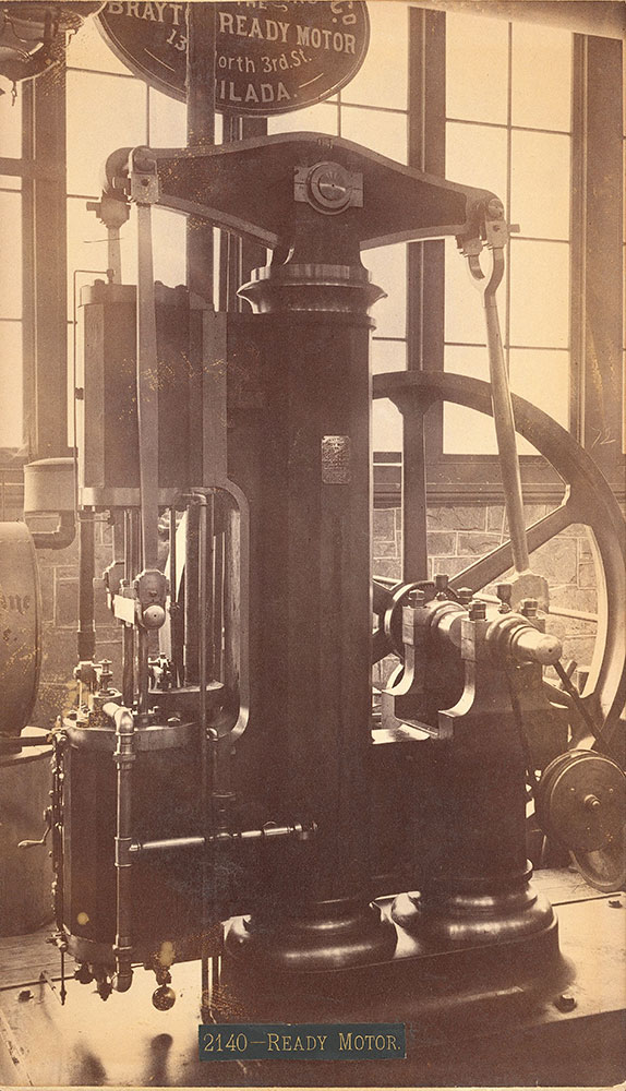
25215 forum posts 3105 photos 1 articles | So here is tonights homework which takes a slightly different form to what has previously been posted. Rather than trying to replicate a drawing here is an old etching of the "Brayton Ready Motor" that I have been helping Graham Corry of Alyn Foundry fame with by drawing some patterns.
You are free to use whatever methods you like so anything from Crayon, chalk or charcoal right upto a fancy 3D rendering will be considered and can also just be a 2D side view or 3D model Only criteria to meet is that the iron flywheel will need to have a finished size of 15" dia (381mm) rim 1 1/2" wide and hub 1 5/8" wide. No cheating by searching around on the net for what I may have already posted, the third version is the one we have settled on. I'll post mine in a day or so.
J
PS if anyone has the capacity to 3D print the pattern at a reasonable cost of can suggest a company/individual Myself and graham would be interested to know. CNC routing from foam may also be an option. Edited By JasonB on 22/07/2020 20:15:08 |
| SillyOldDuffer | 23/07/2020 14:09:31 |
| 10668 forum posts 2415 photos | Posted by JasonB on 22/07/2020 19:11:27:
So here is tonights homework ... J I'm so easily distracted! Reading the blurb to the side of the drawing (which doesn't quite flow properly), I see this isn't a Steam Engine. It's an early gas engine, using Internal Combustion.
If I decode the words correctly the engine is fed a pre-compressed mixture of fuel & air and the top half of the cylinder pumps it into a reservoir hidden inside the pretty fluted column. From there, the fuel passes via a throttle and a wire mesh flame trap direct into the bottom of the cylinder, where it is ignited by a continuously lit open flame underneath.
It doesn't work like a modern IC engine, where intake, burn and exhaust happen inside a cylinder sealed and opened by valves in concert with timed ignition. Rather it appears fuel and air are pumped into Brayton's cylinder throughout the power stroke, and the mix is ignited immediately by the flame. It must rely on the flywheel to overcome the pressure generated by ordinary burning to push the still burning exhaust out. I can't see in the picture where the exhaust vent is, possibly exhaust just flashes out of holes in the cylinder base. The wire-mesh flame trap is needed to stop fuel/air in the reservoir igniting and flashing back to the main fuel tank, kerboom. The operating cycle was first described by Ericsson, then rediscovered by Joule, and implemented by Brayton. I notice the engine wasn't demonstrated to the Judges at the Exhibition, and suspect it was a tad too dangerous to attract paying customers! Most of the pictures I found on the web of Brayton's Ready Engine show later models which looks to have been tamed. In the 1876 version, the power and pump cylinders have been separated (ie flywheel drives a separate pump), and the pump creates a vacuum sucking liquid fuel through a nozzle into an air-stream as a carburettor.
Other layouts exist though - this one shows an engine more like Jason's etching, with a clue it runs on Benzene:
All this to avoid doing the hard part of Jason's homework - recreating a buildable model engine from a 19th century woodcut... Dave |
| JasonB | 24/07/2020 20:16:23 |
25215 forum posts 3105 photos 1 articles | Dave, good to know you enjoyed the diversion into the Brayton cycle but it's no excuse for late homework! This is my effort on the flywheel, not quite right where the spokes blend into the rim but Alibre trips up sometimes when trying to add fillets to a tapering lofted ellipse following a curved path when it intersects with another compound curved surface. Nothing that can't be sorted with some body filler on the pattern before casting. This is one half of the pattern that has draft angles and shrinkage allowance, the other is the opposite hand so that the spokes match when the two halves go together
And this is a rendering of how it should look when machined.
|
| blowlamp | 25/07/2020 00:52:39 |
1885 forum posts 111 photos | I just traced a bit & eyeballed the rest.
Martin.
|


Please login to post a reply.
Magazine Locator
Want the latest issue of Model Engineer or Model Engineers' Workshop? Use our magazine locator links to find your nearest stockist!
Sign up to our Newsletter
Sign up to our newsletter and get a free digital issue.
You can unsubscribe at anytime. View our privacy policy at www.mortons.co.uk/privacy
Latest Forum Posts
- *Oct 2023: FORUM MIGRATION TIMELINE*
05/10/2023 07:57:11 - Making ER11 collet chuck
05/10/2023 07:56:24 - What did you do today? 2023
05/10/2023 07:25:01 - Orrery
05/10/2023 06:00:41 - Wera hand-tools
05/10/2023 05:47:07 - New member
05/10/2023 04:40:11 - Problems with external pot on at1 vfd
05/10/2023 00:06:32 - Drain plug
04/10/2023 23:36:17 - digi phase converter for 10 machines.....
04/10/2023 23:13:48 - Winter Storage Of Locomotives
04/10/2023 21:02:11 - More Latest Posts...
- View All Topics
Support Our Partners


Shopping Partners
Subscription Offer

Latest "For Sale" Ads
- Reeves** - Rebuilt Royal Scot by Martin Evans
by John Broughton
£300.00 - BRITANNIA 5" GAUGE James Perrier
by Jon Seabright 1
£2,500.00 - Drill Grinder - for restoration
by Nigel Graham 2
£0.00 - WARCO WM18 MILLING MACHINE
by Alex Chudley
£1,200.00 - MYFORD SUPER 7 LATHE
by Alex Chudley
£2,000.00 - More "For Sale" Ads...
Latest "Wanted" Ads
- D1-3 backplate
by Michael Horley
Price Not Specified - fixed steady for a Colchester bantam mark1 800
by George Jervis
Price Not Specified - lbsc pansy
by JACK SIDEBOTHAM
Price Not Specified - Pratt Burnerd multifit chuck key.
by Tim Riome
Price Not Specified - BANDSAW BLADE WELDER
by HUGH
Price Not Specified - More "Wanted" Ads...
Get In Touch!
Do you want to contact the Model Engineer and Model Engineers' Workshop team?
You can contact us by phone, mail or email about the magazines including becoming a contributor, submitting reader's letters or making queries about articles. You can also get in touch about this website, advertising or other general issues.
Click THIS LINK for full contact details.
For subscription issues please see THIS LINK.
Digital Back Issues


Donate

 Register
 Log-in
Model Engineer Magazine
- Percival Marshall
- M.E. History
- LittleLEC
- M.E. Clock

ME Workshop
- An Adcock
- & Shipley
- Horizontal
- Mill

Subscribe Now
- Great savings
- Delivered to your door

Pre-order your copy!
- Delivered to your doorstep!
- Free UK delivery!
All Forum Topics > CAD - Technical drawing & design > Old School Drawing Exercises and 2D CAD