Forum sponsored by:

Copper boiler plate flanging, or not?
Why are copper plates in boilers flanged?
| SillyOldDuffer | 22/08/2020 14:33:48 |
| 10668 forum posts 2415 photos | I suggest Bob starts another thread asking 'What's the best way for a beginner to build a working steam locomotive or traction engine?" Not something I've every wanted to do, but it's a minefield, perhaps requiring the beginner to become moderately expert before attempting it. UK hurdles include:
Seems to me making a loco or traction engine is a major investment and there aren't any short-cuts apart from buying a manufactured or second-hand engine. To build one I'd have to address multiple shortcomings in myself and my workshop. I'd start with a well-documented small engine specifically chosen as an easy beginner project, and be prepared to write it off as a training exercise. I don't trust published plans and always redraw them as necessary to spot mistakes and make sure I've understood them. Recognising I'm a long way off being able to solder a boiler successfully, I'd consider buying one. But I don't think throwing money at the problem is the answer, mostly it's down to me. To sort myself out, I'd join a club and establish relationships with the inspector and anyone else prepared to help. Timescale: years! Which loco or traction engine would the forum recommend as a good starter project for a beginner? Simple design, trustworthy plans, good support, kits that match the plans, and no exotic materials etc. As Model Engineering is a major challenge compared with gluing Airfix planes together or putting up self-assembly furniture I'm not too worried by suppliers providing parts and guidance rather than sure-fire guarantees. Quite a few on the forum work from raw materials, do their own design, and make their own tools and castings etc. It's what I aspire to. Dave |
| Andrew Johnston | 22/08/2020 14:53:52 |
 7061 forum posts 719 photos | Posted by SillyOldDuffer on 22/08/2020 14:33:48:
Good grief, that sounds too hard for me; I'd better not try building anything. Andrew |
| duncan webster | 22/08/2020 14:55:57 |
| 5307 forum posts 83 photos | Posted by JasonB on 22/08/2020 07:25:09:
Duncan, As per at least the three published drawings the boiler will not have the preferred separate water gauge feed as it only has a single manifold hole, test code prefers separate if practcable to fit which it is.(test CODE 6.6) .........Jason has subtly changed tack. I absolutely agree with the need for water gauge to have its own connection, but in his earlier post he stated that butt strap joints are not preferred in the current UK code without giving us a reference to such a code. Now he refers to fittings for water gauges and gives a reference to what I assume is The Boiler Test Code 2018 volume 1. This actually refers to butt strap joints at clause 7.1.e where it says that 'Butt straps in copper boilers shall be examined to indicate full penetration of silver solder has been achieved before other jointing is progressed' No one can disagree with that, but it implicitly accepts the use of butt straps. A continuous plate might be stronger than a butt strap, but would be a case of the best being the enemy of the good, if it is strong enough with a butt strap it is strong enough full stop, no point making it stronger |
| Phil H1 | 22/08/2020 15:21:53 |
| 467 forum posts 60 photos | Duncan, I think Jason answered it earlier. He said that the external butt strap would interfere with the design of that particular traction engine. Phil H Edited By Phil H1 on 22/08/2020 15:22:33 |
| Dave Halford | 22/08/2020 15:33:11 |
| 2536 forum posts 24 photos | Posted by Bob Worsley on 22/08/2020 12:17:57:
I think now that copper is a safe material to make a 100 psi boiler from. Why? It is malleable and ductile, the flanging give a huge safety margin on the joints, propane can't damage the copper, silver solder is a safe material because if the joints are too large then it simply won't join. If the boiler is going to fail then all these make it fail slowly, it will tear or pull apart. Actually rather impressive. Apparently LBSC tested a boiler to destruction but no issue number where the results are given, can it be found and added this thread please?
I was at the Midland show a few years ago and was told a tale by boiler inspector from one of the Southern clubs. They failed a bare boiler for bad joints though it held pressure. A decision was made to test to destruction so a foxhole was dug, everything was closed off on the boiler, water added, the fire was lit and a healthy distance was put between it and watchers. It failed by going Phutt. Edited By Dave Halford on 22/08/2020 15:34:26 |
| Roger Best | 22/08/2020 15:54:17 |
 406 forum posts 56 photos |
The rest should be less worrying. |
| JasonB | 22/08/2020 16:44:32 |
 25215 forum posts 3105 photos 1 articles | Duncan when talking about butt straps I have only said it is not preferred by many boiler inspectors and a full wrapper in now what tends to be used particularly as it is brazed, this is born out by what reeves have said and supplied. 7.1 Actually says butt straps on barrel joints not wrappers.When mentioning that there are parts of the code it does not meet that has been separate from the joint issue and confirmed today as the gauge feed. No change of tack, just two separate issues you have treated as one. Bob I really worry about you building this boiler, the other day I pointed out the way the throatplate on the Minnie is constructed and you had miss read that. I have the book and the drawings you mention and they are NOT the same there are some subtle differences not least the 13swg you have already said the design drawing show yet the book shows 10swg on one page and 13swg on another I suggest you also read the first few paragraph of the Copper Boiler chapter where Haining lists the changes from his 1962 design and what he now (1982) suggests doing Another thing that you may fall foul of if you merrily carry on without talking to an inspector is that the Drawings and book have failed to show the blowdown valve boss and there is also no provision for washdown holes. The Magazine article does show a blowdown. As Said a propane torch can melt copper, I know of two builders of the 2" Fowler A7 who managed to burn/melt the fire tubes effectively scrapping the boilers, a problem as the tubes are thinner than the plates so heat up faster and if you go with your thick unflanged plates even more likely to happen. Please don't "just copy" another design for a much smaller boiler with a lower 50psi working pressure, Do the calculations or if you can't talk to a boiler inspector. If you can't get to a club at the moment then work on some other parts of the engines until you can, they should want to see it during construction anyway not just when complete.
|
| Dave Halford | 22/08/2020 17:26:29 |
| 2536 forum posts 24 photos | Posted by Bob Worsley on 22/08/2020 12:17:57:
It is ironic that it was the 16hp one I was going to build, but Graham Howard of Brunell Model Engineering decided he wasn't going to supply more than a few of the castings. Paid £2300 for nearly nothing, plus £2500 for a commercial boiler and now got a pile of scrap. If a commercial boiler is CE marked and the paperwork is good then I believe it should be OK to be steam tested when completed at the quoted pressure. The 16HP has the same gears flywheel and crank mounts as Superba from Blackgates. The cylinder does not have to be the Church valve version the original it was supposed to be based on was built with a normal slide valve. |
| JasonB | 22/08/2020 18:10:23 |
25215 forum posts 3105 photos 1 articles | Dave Crank and 2nd shaft have different PCD between Superba and 16NHP therefore different gears and the horn brackets 9 Crank mounts ? ) are not the same, I believe the flywheels are the same castings. However both hornbrackets and gears can be made from scratch without the need for castings as can a lot of the other parts so no need to write off the boiler with the added bonus of making it look more like a 16nhp than haining's "stand off scale" version. Edited By JasonB on 22/08/2020 18:12:44 |
| Dave Halford | 22/08/2020 19:29:50 |
| 2536 forum posts 24 photos | Jason, You perfectionist you. The real one is a very different beast, however Haining's designs for the 16hp (ME 1st may 81 page 558 gear table) lumps the 16 and Superba together with the same gears. This table also appears in the Superba build. So a heck of a compromise, but allegedly do-able if you want to.
|
| Paul Kemp | 22/08/2020 19:49:54 |
| 798 forum posts 27 photos | Posted by Dave Halford on 22/08/2020 17:26:29:
Posted by Bob Worsley on 22/08/2020 12:17:57:
It is ironic that it was the 16hp one I was going to build, but Graham Howard of Brunell Model Engineering decided he wasn't going to supply more than a few of the castings. Paid £2300 for nearly nothing, plus £2500 for a commercial boiler and now got a pile of scrap. If a commercial boiler is CE marked and the paperwork is good then I believe it should be OK to be steam tested when completed at the quoted pressure. The 16HP has the same gears flywheel and crank mounts as Superba from Blackgates. The cylinder does not have to be the Church valve version the original it was supposed to be based on was built with a normal slide valve. Even if the commercial boiler is not CE marked as long as you can prove it was built before CE marking became mandatory (2002) rings a bell but as its historic it is no longer listed in the orange code (pretty sure it's in the old blue version though) then it can still be tested no problem. There are still a few pre CE boilers incorporated into models that builders are only just completing! Paul. |
| JasonB | 22/08/2020 19:58:31 |
25215 forum posts 3105 photos 1 articles | Yes you are right Dave, I had just quickly looked at the hornplate drawing which is the Z7S even though part of the "Superba" drawings. The gear drawings have Superba and 16NHP as same size gears. However if I ever get round to building the Superba that I have the castings for it will have different gearing more in keeping with full size as will the 120psi BB1 I mentioned being made by someone else.
|
| Bob Worsley | 25/08/2020 10:01:50 |
| 146 forum posts | JB, don't be worried, I look, read and think. I missed that throatplate overlap probably because at that moment I didn't see it as being important which way round it was made, you corrected that, thanks. But I will say that continuing reading the ME and issue 3781 has the Waverly boiler with this joint the other way round, Martin Evans. I mentioned I had contacted Reeves about the modified BB boiler. Not much of a reply. But the boiler as they supplied needs a joint ring inside the boiler to join the barrel to the wrapper. This ring is flat material 16" long by 3/4" by 3mm. So will go all the way around the boiler. Being 3/4" gives 3/8" on barrel and wrapper. The water gap between firebox front and throatplate is 3/8". So the ring completely blocks this? I have asked what I am supposed to do. Similarly the side stays are provided as copper rivets, what am I supposed to do with them, different to drawing. Yes, propane can melt copper, but it can't boil/vapourise it like an OA torch can. SoD makes some important points about old, out of date, builders or designs? I like copper for boilers though, its cost is only part of the cost of the model, but still less than a miniscule holiday. Thanks to all again.
|
| JasonB | 25/08/2020 10:24:27 |
25215 forum posts 3105 photos 1 articles | The joint ring is typically only the full width around the top half of the boiler and cut back to just over half so that it clears the water space but contacts the curved top edge of the throat plate and extends into the lower half of the barrel. Similar to this.
Omit the threaded stays and poke the rivits through from the inside, bend them slightly on the outside so they don't fall out during soldering and cut them off afterwards. I would also suggest not threading the larger stays where the hornplates attach. Out of interest what diameter rivits do they supply? BUT do confirm these points with your boiler inspector first As you seem to have a collection of MEs can I suggest reading "My first boiler" by Julia Old starting with 4325, the third part in Edited By JasonB on 25/08/2020 15:50:54 |
| Neil Wyatt | 25/08/2020 15:41:45 |
 19226 forum posts 749 photos 86 articles | I see Bob you aren't a member of a club. I'd be very wary of changing from an accepted design without confirming the changes with a boiler inspector first. Bear in mind that even a change which intuitively makes the boiler stronger (such as using thicker material) will cascade down into changes to many of the boiler dimensions so making parts 'to size' they may not even fit together and then you will have to make more changes which the inspector will need to approve. Neil |
| Dave Halford | 25/08/2020 17:22:17 |
| 2536 forum posts 24 photos | Posted by JasonB on 25/08/2020 10:24:27:
The joint ring is typically only the full width around the top half of the boiler and cut back to just over half so that it clears the water space but contacts the curved top edge of the throat plate and extends into the lower half of the barrel. Similar to this.
Omit the threaded stays and poke the rivits through from the inside, bend them slightly on the outside so they don't fall out during soldering and cut them off afterwards. I would also suggest not threading the larger stays where the hornplates attach. Out of interest what diameter rivits do they supply? BUT do confirm these points with your boiler inspector first As you seem to have a collection of MEs can I suggest reading "My first boiler" by Julia Old starting with 4325, the third part in Edited By JasonB on 25/08/2020 15:50:54 I guess that explains This floating ring / strap in Nigel Bennet's scrap BB1 boiler, it's supposed to be silver soldered to the bridge the barrel to wrapper joint and got forgotten. |
| JasonB | 25/08/2020 18:27:40 |
25215 forum posts 3105 photos 1 articles | That''s the thing, not only forgotten but shows the boiler was not constructed in an ideal sequence, The barrel, throatplate and wrapper should have been one early assembly then it is easy to inspect the joint to check solder has penetrated Looks like a lot more was assembled before soldering, joint may have only been fluxed from the outside so little chance of the externally applied solder going where it should. |
| Bob Worsley | 26/08/2020 17:55:46 |
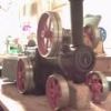
| 146 forum posts | That drawing is exactly what I was expecting from Reeves, but no, just telling me to return it in an undamaged condition. Snag is they use thick paper from a shredder and it isn't easy to disinter the parts from this paper. Was missing the firehole ring, found it in the wheely bin. No other progress either, trying to contact Tyler Steam Models to ask about drawings, buy a new set if necessary, but no response to email or phone call. That photo of the BB boiler is impressive, built and safe! Would probably pass all the safety tests, simply because the copper and solder do make a good joint. As to the rivet stays, they are 3/16" diameter, what I wondered was cutting a cross in the end, using a four way chisel to splay the ends out flat and then soldering. Different to threading and nuts, but the volume of copper mechanically holding the stay is the same. End of rivet will need to be annealed prior to splaying. Any thoughts?
|
| SillyOldDuffer | 26/08/2020 18:58:13 |
| 10668 forum posts 2415 photos | Posted by Bob Worsley on 26/08/2020 17:55:46: ... As to the rivet stays, they are 3/16" diameter, what I wondered was cutting a cross in the end, using a four way chisel to splay the ends out flat and then soldering. Different to threading and nuts, but the volume of copper mechanically holding the stay is the same. End of rivet will need to be annealed prior to splaying. Any thoughts?
The geometry weakens the joint. In the drawing below Stay 'A' is splayed and soldered, while Stay 'B' passes through the shell and is held by a nut.
When Stay 'A' is stressed, all the force is taken by the solder in tension, marked in red. And the solder could be fatigued due to movements when the boiler heats up and cools down. The arrangement is weaker than Stay 'B' where the same force is transferred by the nut to the outside of the shell in compression (green). Provided the nut and stay are threaded competently, the joint will be as strong as the stay. I think Stay B also gives more chance of spotting trouble during maintenance because the joint isn't hidden inside the boiler. No experience myself, but I'd guess Stay B would be easier to fit too. Dave
|
| JasonB | 26/08/2020 19:06:50 |
25215 forum posts 3105 photos 1 articles | Dave, I suspect Bob was thinking of splaying the end once it had passed through the two plates somewhat like a bifricated rivit. No nuts are used when rivits are used as stays so your second option is also incorrect too. You are correct that B would be easier to fit as how on earth are you meant to apply solder to A when it's inside the water legs or see if the joint ha sflowed? Don't see any point in splaying it either way, stick with a tried and trusted method, I'm sure the boiler inspector will say the same
Edited By JasonB on 26/08/2020 19:12:41 Edited By JasonB on 26/08/2020 19:18:15 |


Please login to post a reply.
Magazine Locator
Want the latest issue of Model Engineer or Model Engineers' Workshop? Use our magazine locator links to find your nearest stockist!
Sign up to our Newsletter
Sign up to our newsletter and get a free digital issue.
You can unsubscribe at anytime. View our privacy policy at www.mortons.co.uk/privacy
Latest Forum Posts
- *Oct 2023: FORUM MIGRATION TIMELINE*
05/10/2023 07:57:11 - Making ER11 collet chuck
05/10/2023 07:56:24 - What did you do today? 2023
05/10/2023 07:25:01 - Orrery
05/10/2023 06:00:41 - Wera hand-tools
05/10/2023 05:47:07 - New member
05/10/2023 04:40:11 - Problems with external pot on at1 vfd
05/10/2023 00:06:32 - Drain plug
04/10/2023 23:36:17 - digi phase converter for 10 machines.....
04/10/2023 23:13:48 - Winter Storage Of Locomotives
04/10/2023 21:02:11 - More Latest Posts...
- View All Topics
Support Our Partners


Shopping Partners
Subscription Offer

Latest "For Sale" Ads
- Reeves** - Rebuilt Royal Scot by Martin Evans
by John Broughton
£300.00 - BRITANNIA 5" GAUGE James Perrier
by Jon Seabright 1
£2,500.00 - Drill Grinder - for restoration
by Nigel Graham 2
£0.00 - WARCO WM18 MILLING MACHINE
by Alex Chudley
£1,200.00 - MYFORD SUPER 7 LATHE
by Alex Chudley
£2,000.00 - More "For Sale" Ads...
Latest "Wanted" Ads
- D1-3 backplate
by Michael Horley
Price Not Specified - fixed steady for a Colchester bantam mark1 800
by George Jervis
Price Not Specified - lbsc pansy
by JACK SIDEBOTHAM
Price Not Specified - Pratt Burnerd multifit chuck key.
by Tim Riome
Price Not Specified - BANDSAW BLADE WELDER
by HUGH
Price Not Specified - More "Wanted" Ads...
Get In Touch!
Do you want to contact the Model Engineer and Model Engineers' Workshop team?
You can contact us by phone, mail or email about the magazines including becoming a contributor, submitting reader's letters or making queries about articles. You can also get in touch about this website, advertising or other general issues.
Click THIS LINK for full contact details.
For subscription issues please see THIS LINK.
Digital Back Issues


Donate

 Register
 Log-in
Model Engineer Magazine
- Percival Marshall
- M.E. History
- LittleLEC
- M.E. Clock

ME Workshop
- An Adcock
- & Shipley
- Horizontal
- Mill

Subscribe Now
- Great savings
- Delivered to your door

Pre-order your copy!
- Delivered to your doorstep!
- Free UK delivery!
All Forum Topics > Workshop Techniques > Copper boiler plate flanging, or not?