Forum sponsored by:

The Workshop Progress Thread
Report your modelling and workshop milestones in this thread.
| ian j | 19/12/2015 13:01:00 |
 337 forum posts 371 photos | Thought I would share with you a short video of my Hit & Miss engine running. It's The Farm Boy built from Jerry E Howell (USA) plans using bar stock ( Aluminium from local Non Ferrous scrap yard) most of the other material I already had. The only castings are the fly wheels which I had cast locally using a partly machined one I purchased from the Home workshop ads as a pattern, It involved cutting two gears which was a first for me It's running using a minimag Co. coil & miniature ignition module, a 70%/30% mixture of colemans fuel/methanol. I think I'm hooked on hit & miss engine now !! Ian Edited By JasonB on 19/12/2015 13:16:45 |
| JasonB | 19/12/2015 13:18:14 |
 25215 forum posts 3105 photos 1 articles | Looks to be running well but would be nicer with some sound. I think the Farm Boy is by far the nicest of the barstock hit & miss designs, are you intending to give it a lick of paint? J |
| ian j | 19/12/2015 13:28:19 |
337 forum posts 371 photos | Jason, Yes I intend to paint it .I'm thinking sateen finish dark green. There's a reason for no sound. At the moment there is a tight spot between the two gears and it makes an annoying squeaking sound, I'm hopping this will disappear after a bit of running in? Ian |
| JasonB | 19/12/2015 13:30:28 |
25215 forum posts 3105 photos 1 articles | Some people put a bit of valve grinding paste on the gear and run them in that way, not tried it myself though. I don't think the farm boy has it but several of the hit & miss engines that I have done have the end of the timing gear stud turned eccentric to the shaft so you can just rotate it slightly to adjust the mesh of the gears Edited By JasonB on 19/12/2015 13:32:18 |
| JasonB | 20/12/2015 13:44:35 |
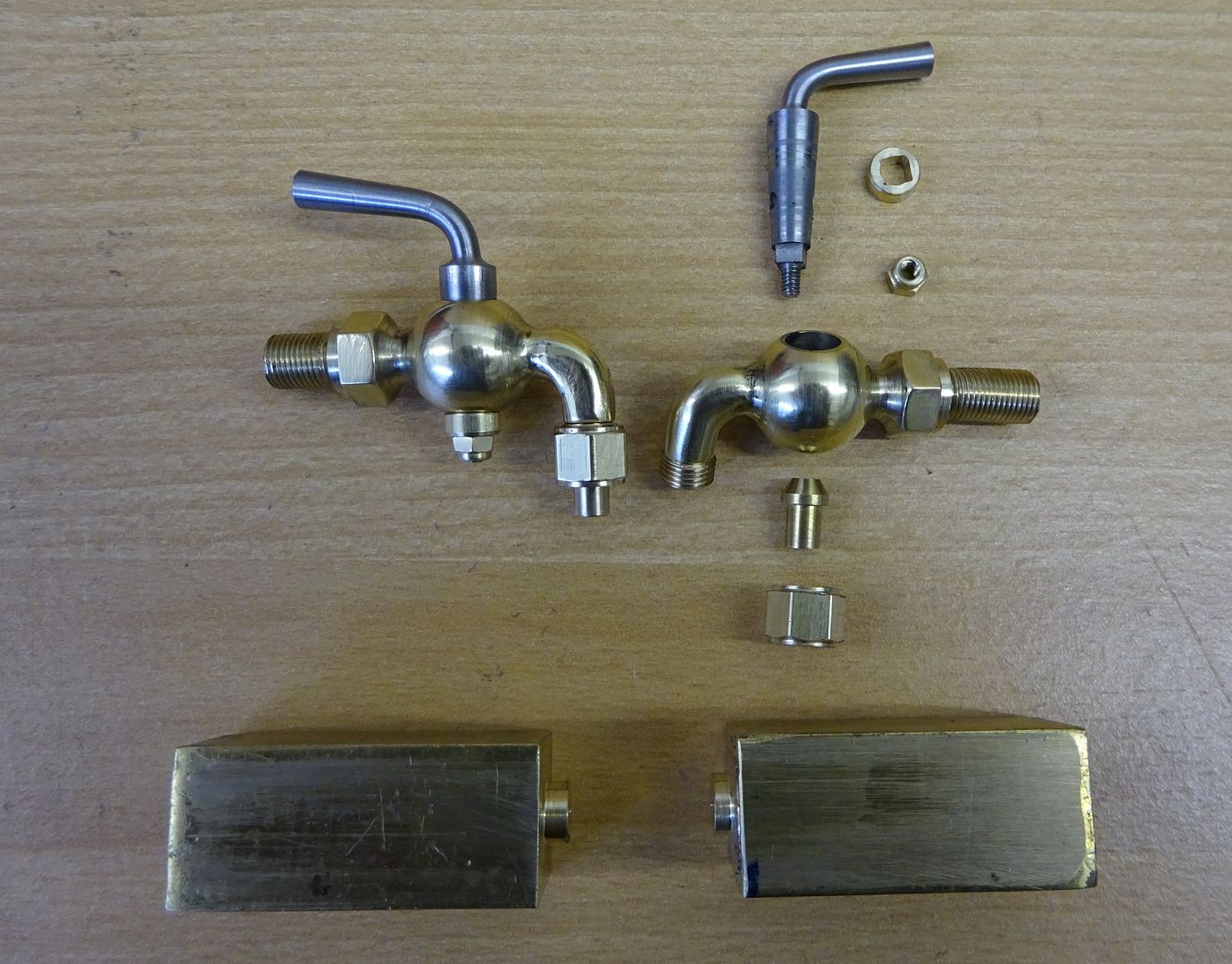
25215 forum posts 3105 photos 1 articles | Seems I have spent most of the weekend playing with my cocks but I'm happy with the outcome. They started life as some salvaged 5/8" sq brass and were carved from that with just the spout thread being a soldered on piece (no room for a die)
And a pic of the tapered reamer used to form the conical hole which was turened at the same setting as the spindles which were lapped in with 600g powder and seems to pass the blow test.
|
| Neil Wyatt | 20/12/2015 16:13:52 |
 19226 forum posts 749 photos 86 articles | Like both of those (engine and taps). Neil |
| Andrew Johnston | 20/12/2015 21:41:14 |
 7061 forum posts 719 photos | Having spent part of yesterday slogging away on the Bridgeport machining heatsinks for a client this evening I was able to construct another Heath Robinson setup to machine the water pump spigot for the bypass valve:
The spigot is machined to length and diameter, drilled though and then opened up to form a flat bottomed hole, using a home made D-bit. Finally the outside is screwcut 3/8" BSP. This is a rare chance to use the small faceplate - it's not that well endowed with slots. Despite the helpful sticker giving a top speed of 1200rpm the machining was done at a more sedate 260rpm. Now that everything is set up it shouldn't take long to swap over castings and machine the other two water pumps. Interesting to see the nifty cocks made by JasonB, and the strange brass swarf. For the water pumps I need to make some elbows, which will need silver soldering. The elbows will only see warm water, so could be brass, but I wondered about gunmetal. My normal supplier of gunmetal states that it is leaded. i know that using lead based solder prior to silver solder is bad. So does that mean that leaded gunmetal may not silver solder properly? This question will gain importance when I get around to the other boiler fittings, some of which will definitely be seeing steam. Andrew |
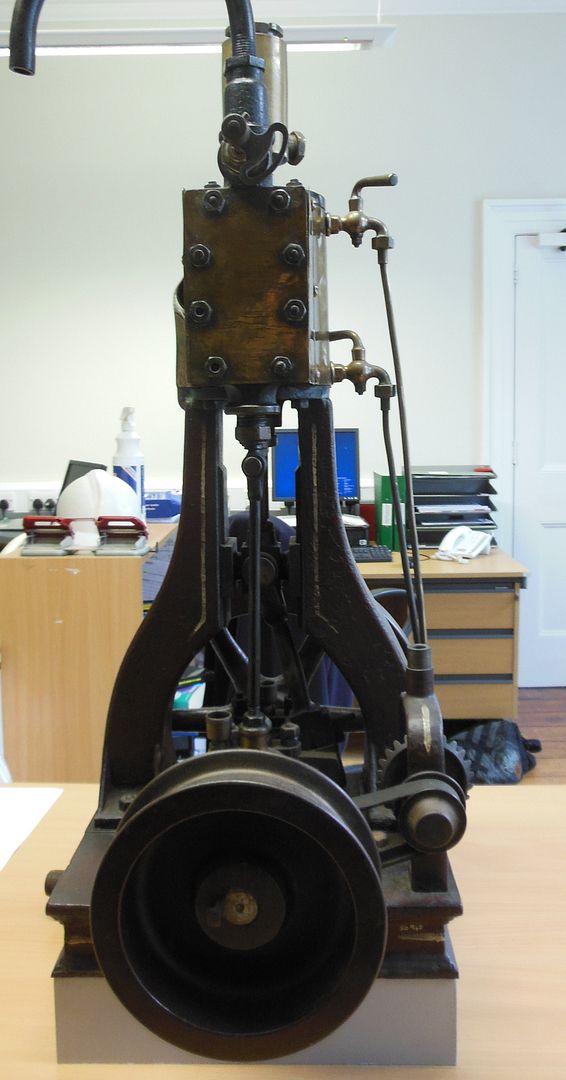
| JasonB | 26/12/2015 20:13:15 |
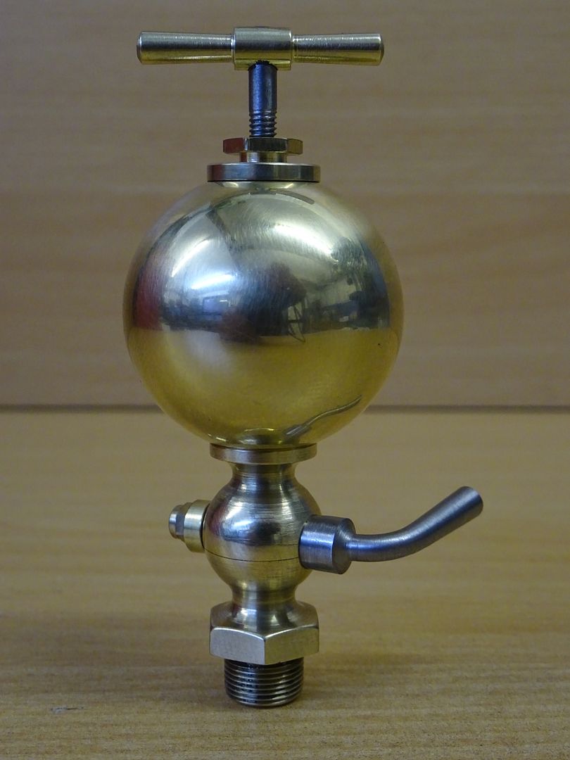
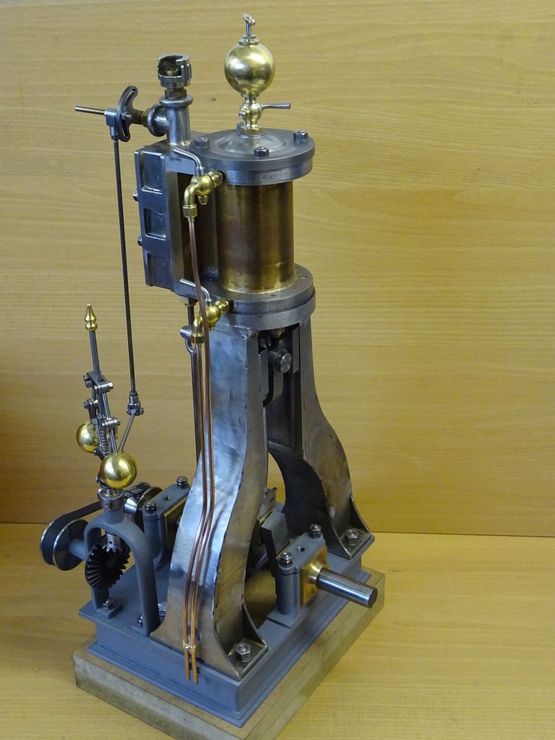
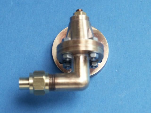
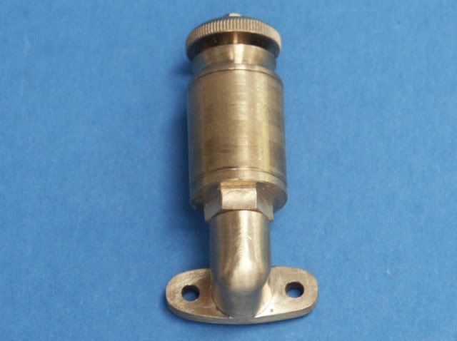
25215 forum posts 3105 photos 1 articles | Andrew, just seen your post, must have missed it earlier. The cylinder that I showed earlier and that you have seen in the flesh is leaded bronze SA660 and soldered OK, same with a lot of the fittings on my Fowler. Can you not drill round the corner of your elbows and therefore make them from solid, I managed to do that on teh drains and always do it with the cast elbows that I use on the hit & miss engines. More Baubles as its christmas, this time the cylinder lubricator, the valve was done in much the same way as the drains, just a quick regrind of the form tool and I had made the third spindle at teh same time as the others so could use the same taper reamer. I did make my own ball this time, 1.25" dia and hollowed out.
Also plumbed up the drain cocks
Those with a keen eye will also spot that the governor drive pullies and belt are in place and I can confirm that it is a working governor J
Edited By JasonB on 26/12/2015 20:26:30 |
| Andrew Johnston | 26/12/2015 22:17:11 |
7061 forum posts 719 photos | Looking good Jason - where are you getting the designs from? Are they on the drawings or to your own design? I was wondering why nobody had picked up on my question. It was beginning to look like no-one was reading the 'Workshop Progress' thread, which would be rather ironic given the recent fisticuffs bemoaning the lack of engineering input on the forum. From a combination of sources it looks like silver soldering LG2 should be no problem. I don't understand what you mean by drilling round the corner? Apart from mucking about with the PathPilot installation on the CNC mill today I also machined to length and rolled a new front wheel rim to replace the duff one. Here are the home made rolls and said new rim:
I've also cleaned up the large scrap aluminium plate ready to be used as a jig for building the wheels. The plate was cheap from my normal aluminium supplier as I asked for a minimum size, didn't care about thickness and most of all didn't care about gouges. It's win-win, they can get more than scrap price and I get it much cheaper than normal. Andrew |
| John Stevenson | 27/12/2015 00:10:24 |
 5068 forum posts 3 photos | Andrew, More details please of the rollers. How do you get the ring out after rolling and what thickness is the rim you rolled. |
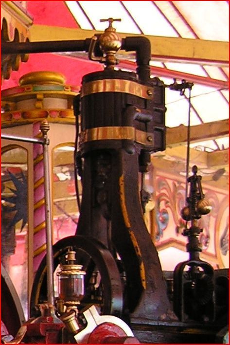
| JasonB | 27/12/2015 07:56:39 |
25215 forum posts 3105 photos 1 articles | Andrew, I'm working from some photos of an original engine taken by another forum memmber, (you may have seen his full size one at Fornsett or in ME recently) and also the odd photo found on the net. I have drawn it all up from these at 2/3rd scale and it will be featured in ME along with a full set of drawings.
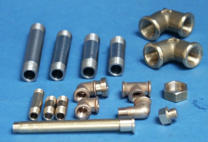
On your fittings would it not be easier to use bronze bar as its a bit harder than gunmetal and readily available in various round bars? By drilling around the corners I wa srefering to drilling in from each end of the elbow so the holes meet in the middle and hopefully don't come out the other side. That is how the drain cocks were done
As were these elbows & tee
Edited By JasonB on 27/12/2015 07:58:56 |
| KWIL | 27/12/2015 11:20:45 |
| 3681 forum posts 70 photos | Andrew, LG2 silver solders fine Jason, those fittings look great |
| Andrew Johnston | 27/12/2015 20:52:48 |
7061 forum posts 719 photos | After wasting a good portion of the day trying to get tool offsets working in PathPilot I managed to salvage something by marking out, drilling and tapping (1/2" UNC) the fixing holes on the jig plate for my traction engines wheels. Only the holes needed for the front wheels have been done so far, but they'll keep me busy for quite a while.
Andrew |
| Andrew Johnston | 27/12/2015 21:01:51 |
7061 forum posts 719 photos | John: The rolls were specifically designed for rolling the rims of my traction engine wheels. The rolls are a bit over 2" diameter and the gears are 13 teeth, 5DP. The front rims, as seen in the picture, are 3" by 1/4" and the rears are 5-1/4" by 3/16". To simplify the design the rolled metal goes down under the mill table. A CAD model showed that there was enough clearance on the front wheels (14.5" OD) to do this. Again to simplify the design the rolled rims are simply opened up enough to clear the rolls to remove them and then allowed to spring back. In the event I didn't roll the rear rims on these rolls as somebody on another forum kindly offered me the use of his larger geared rollers. The rolls were originally intended to have deep grooves to roll the T-rings, but I got these laser cut in quadrants to be welded together, so the grooves were never machined. The rolls exist as a CAD model so drawings are available. Andrew |
| Andrew Johnston | 28/12/2015 10:57:35 |
7061 forum posts 719 photos | KWIL: Thanks, that three people saying it will be fine silver soldering LG2, so I'll stop worrying about it. Ok, I understand about the drilling now, that's what I was going to do, except that I'll probably use a ballnose slot drill to get a nice smooth transition at the bend. This is what I want the elbows to look like:
I don't see how I can make them from solid without a lot of filing to get a nice smooth finish round the bend as it were! It should be simpler to silver solder two parts together? For scale the OD is 3/4". Andrew |
| JasonB | 28/12/2015 13:11:43 |
25215 forum posts 3105 photos 1 articles | Isn't that what you have a CNC machine for I'll sketch out how I did the Fowler elbows which are similar as I did not do a straight forwards mitre joint. J |
| John Stevenson | 28/12/2015 13:19:29 |
5068 forum posts 3 photos | So when are we going to get you over to the dark side then Jason ?
[Edit ] Forgot the smiley. Edited By John Stevenson on 28/12/2015 13:20:14 |
| JasonB | 28/12/2015 13:25:11 |
25215 forum posts 3105 photos 1 articles | Well if you have got a spare machine knocking about John, you owe me a favour At least I will have the advantage over you of being able to draw the part I want to make Edited By JasonB on 28/12/2015 13:26:47 |
| John Stevenson | 28/12/2015 13:30:55 |
5068 forum posts 3 photos | Ouch, that was below the belt.
Email sent. Edited By John Stevenson on 28/12/2015 13:31:28 |
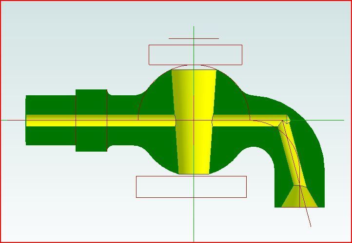
| JasonB | 28/12/2015 13:38:51 |
25215 forum posts 3105 photos 1 articles | Andrew, if you make it like this by plunging half way in with a slot drill the socket that is formed will hold the bertical part nice and firmly and also at right angles and is a lot easier than trying to line up a mitre cut. once soldered you can hold it upside down by the vertical part on teh rotary table to round off the end and then either file the remainder or use a rounding over bit.
Works quite well
J |


This thread is closed.
Magazine Locator
Want the latest issue of Model Engineer or Model Engineers' Workshop? Use our magazine locator links to find your nearest stockist!
Sign up to our Newsletter
Sign up to our newsletter and get a free digital issue.
You can unsubscribe at anytime. View our privacy policy at www.mortons.co.uk/privacy
Latest Forum Posts
- *Oct 2023: FORUM MIGRATION TIMELINE*
05/10/2023 07:57:11 - Making ER11 collet chuck
05/10/2023 07:56:24 - What did you do today? 2023
05/10/2023 07:25:01 - Orrery
05/10/2023 06:00:41 - Wera hand-tools
05/10/2023 05:47:07 - New member
05/10/2023 04:40:11 - Problems with external pot on at1 vfd
05/10/2023 00:06:32 - Drain plug
04/10/2023 23:36:17 - digi phase converter for 10 machines.....
04/10/2023 23:13:48 - Winter Storage Of Locomotives
04/10/2023 21:02:11 - More Latest Posts...
- View All Topics
Support Our Partners


Shopping Partners
Subscription Offer

Latest "For Sale" Ads
- Reeves** - Rebuilt Royal Scot by Martin Evans
by John Broughton
£300.00 - BRITANNIA 5" GAUGE James Perrier
by Jon Seabright 1
£2,500.00 - Drill Grinder - for restoration
by Nigel Graham 2
£0.00 - WARCO WM18 MILLING MACHINE
by Alex Chudley
£1,200.00 - MYFORD SUPER 7 LATHE
by Alex Chudley
£2,000.00 - More "For Sale" Ads...
Latest "Wanted" Ads
- D1-3 backplate
by Michael Horley
Price Not Specified - fixed steady for a Colchester bantam mark1 800
by George Jervis
Price Not Specified - lbsc pansy
by JACK SIDEBOTHAM
Price Not Specified - Pratt Burnerd multifit chuck key.
by Tim Riome
Price Not Specified - BANDSAW BLADE WELDER
by HUGH
Price Not Specified - More "Wanted" Ads...
Get In Touch!
Do you want to contact the Model Engineer and Model Engineers' Workshop team?
You can contact us by phone, mail or email about the magazines including becoming a contributor, submitting reader's letters or making queries about articles. You can also get in touch about this website, advertising or other general issues.
Click THIS LINK for full contact details.
For subscription issues please see THIS LINK.
Digital Back Issues


Donate

 Register
 Log-in
Model Engineer Magazine
- Percival Marshall
- M.E. History
- LittleLEC
- M.E. Clock

ME Workshop
- An Adcock
- & Shipley
- Horizontal
- Mill

Subscribe Now
- Great savings
- Delivered to your door

Pre-order your copy!
- Delivered to your doorstep!
- Free UK delivery!
All Forum Topics > Work In Progress and completed items > The Workshop Progress Thread