Forum sponsored by:

The Workshop Progress Thread
Report your modelling and workshop milestones in this thread.
| Tractor man | 03/12/2015 17:12:32 |
| 426 forum posts 1 photos | Hi all, Just a quick photo of the new boring head for my jig borer, any thoughts on it? It looks pretty robust and seems like quality.
Busy afternoon getting filthy removing all the dried on grime form the cross table and feed screws. Used an ultrasonic cleaner to get all the old grease out of the thrust bearings. I am considering having the table reground as it looks a bit tatty, three drill holes show that someone was careless in the past and I want to disguise them so cast iron pins bonded in before grinding should do the trick.
Hopefully I will get the table ground next week and then refit everything during the evenings. This is just a quick refit rather than a back to bare metal overhaul but I will still repaint her just to take away the tatty looks. Might be tempted into filling a few casting issues with P38 but this is not a concourse machine lol. Regards mick
|
| Andrew Johnston | 05/12/2015 22:34:55 |
 7061 forum posts 719 photos | I've been winging it today. My afternoon tug pilot duty was cancelled on the grounds that it's blowing a fair bit! So instead I've been making wing valves in the workshop:
The wing valves are the white parts on the left, and in situ in the water pump valve body on the right. The valves are made from glass filled PTFE. Straight PTFE is awful stuff for holding tolerances. It moves, it creeps and measures differently ten minutes after you got it bang on the dimension, or so you thought. The glass filled PTFE is in a different league. It machined beautifully using a polished carbide insert intended for aluminium. If the part was 20 thou over-size I could move the cross slide dial 20 thou and after cutting the part was 20 thou smaller, to within a tenth or so. Marvellous! The only downside is that no matter how many times you wash your hands and wipe the tools one still ends up with 'dirty' fingerprints soiling the pristine whiteness. Andrew |
| JasonB | 06/12/2015 15:34:59 |
 25215 forum posts 3105 photos 1 articles | Look good Andrew, will be interesting to see how they perform under steam, I have only seen seats or seals done with PTFE before not the whole valve.
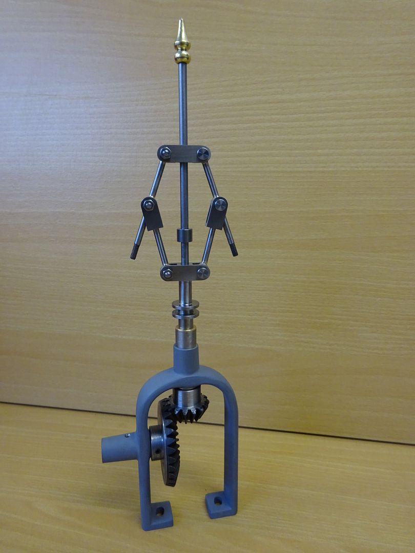
I have spent most of my workshop time this weekend doing the bright bits of the Tidman governor, just waiting for some big brass balls to arrive from the states to finish it off.
|
| Andrew Johnston | 06/12/2015 21:10:27 |
7061 forum posts 719 photos | Posted by JasonB on 06/12/2015 15:34:59:
Look good Andrew, will be interesting to see how they perform under steam, I have only seen seats or seals done with PTFE before not the whole valve. I'd be a lot more worried if it was virgin PTFE; the glass filled PTFE is a totally different animal. I'd be even more worried if it saw steam as they're for the water pump. Is the governor for real or show? Looks excellent either way. I've been looking at the governors on my engines and I'm not sure that brass is heavy enough to allow a working governor? I'm dithering between lead filled hollow balls or carbide. The main problem with carbide is how to cut it, given that the governor balls are fitted as two hemispheres. Andrew |
| JasonB | 07/12/2015 07:27:42 |
25215 forum posts 3105 photos 1 articles | Ah yes its the water pump so should not even get warm. Well I'm hoping it will be a working governor, the balls will be 1" dia brass which is a bit bigger than scale to make sure them have more effect. I may also play with the drive pullies to gear it up a bit more , they are also likely to be the weak link in teh system as getting a small flat belt to run without slipping while putting minimal load on the shaft is not easy. Maybe a shallow straight knurl on the pully surface would help and should not show up too much. J |
| Roderick Jenkins | 07/12/2015 08:58:00 |
 2376 forum posts 800 photos | Andrew, I think one of the sintered tungsten "alloys" may be the answer to your problems. These are " heavy metal" as used in tungsten darts. I bought some from the surplus market some years ago and used some slugs to help balance my 10cc 4 stroke single. Turns like mild steel so making some balls should be straightforward. Supply is something of an issue to MEs but you could try these people **LINK** or **LINK** HTH, Rod |
| Andrew Johnston | 07/12/2015 20:59:27 |
7061 forum posts 719 photos | Rod: Brilliant, thanks! Don't know why I didn't think of tungsten alloys. The limiting factor may be cost. I've used Smiths Metals (the first of your links) in the past for non-ferrous; mainly copper and brass. It will be worth giving them a call and seeing what they can do. At least they're only a few miles down the road from me so I can avoid expensive delivery charges. After a complete fumble last night trying to make the blanks for the water pump rams I managed to get it right this evening. The rams are made from 303 stainless steel. Here is the blank for all three rams being ground to the correct diameter:
The total length of the active part is 10". With a bit of trial and error with the table swivelling screw I managed to get it parallel to within a tenth. To get a nice sliding fit in the water pump I needed to be a few tenths under nominal size. This confirms my view that bronze/gunmetal seems to close up slightly when drilled and reamed, and so ends up slightly undersize. Now all I have to do is hacksaw the blank into three, without the hacksaw slipping and damaging the finish, which was one of last nights foul ups. I was so p*ssed off about it, that it led to a nasty accident with a bottle of red wine and watching trash on the TV until the small hours. Although I didn't stay up to watch it there was a programme on QUEST at 3am which claimed to be about building a live steam loco. Andrew Edited By Andrew Johnston on 07/12/2015 21:00:27 |
| Colin Heseltine | 08/12/2015 13:27:45 |
| 744 forum posts 375 photos | Finally finished adding DRO's to my Cowell's ME90 lathe. I am using YuriysToys android app (TouchDRO) and his controller design. Just need to calibrate them and build another controller box. The current one is running the DRO's on Cowells mill.
Fun job with not too much space to attach the various brackets on the carriage and cross-slide.
Quite pleased with the result.
Colin |
| lancelot | 11/12/2015 18:02:44 |
 63 forum posts 4 photos |
|
| lancelot | 11/12/2015 18:10:48 |
63 forum posts 4 photos | Hi Colin ......sorry for hijacking your post ...it has been a while ... great work on the Cowells ...I have the mill and use very long reach clock gauges...not used to diggy stuff I hope you can see the photo of what I am currently building ...this will keep me going for some time . Cheers, John. |
| Colin Heseltine | 11/12/2015 19:27:20 |
| 744 forum posts 375 photos | John, I also have the mill. If you look in ' the album Twizseven's Bits & Bobs' you will see the DRO's I fitted to that. makes this so much easier and accurate. Which engine is that you are building. Do you have another mill or is all milling done on the Cowells.
Colin |
| lancelot | 11/12/2015 21:37:34 |
63 forum posts 4 photos | Posted by Colin Heseltine on 11/12/2015 19:27:20:
John,. Which engine is that you are building. Do you have another mill or is all milling done on the Cowells. Hi Colin...this one is from the Peter Southworth collection...Peter recently passed on and the castings are now with his old friend Bob Potter ...This is the 1 1/8'' single cylinder rotary valve horizontal...I have two mills, I started off with the Conquest ...from Chester, made the 10v ...score from Stuarts then the James Coombes on this mill plus a lot of other jobs ...I had started the Corliss build some few years ago with the 10'' diam. flywheel which was in two halves....I was only able to mill the faces of the halves ,,,just...basically wrecked the mill far too lightweight for the work ...a club friend finished the flywheel outer face ... after a diagnosis of Parkinsons my motivation was a tad on the low side ...Shed shut ... During this time I bought a Cowells mill...so the interest was alive and a few prods from my grand children got me back in the shed... Yes ...some of the small work was handled by the WEE...Cowells mill a really solid and accurate piece of kit UI use long reach indicators from Mittytoyo...This mill is excellent for this type of job... The Chester is now replaced with one of the mills from Amadale a much heavier and more professional jobby...with an extra long table , very useful when the rotary indexer needs using. Keep her cuttin. John.
|
| Tractor man | 12/12/2015 09:35:08 |
| 426 forum posts 1 photos | The Shaftesbury jig borer is completed, just about...... I discovered the draw bar was 3/8 UNC but the tooling I scrounged was 1/2 UNC. Make a new drawbar was the obvious answer, but the bore of the quill prevented anything larger than 10mm dia. So I make a number of helicoil style inserts with an outside 1/2 UNC thread and a 3/8 UNC inner thread. Bonded them into the tooling and hey presto they all fit the machine now. Table reground and looking good with the drill holes filled. Just a little more tidying up with a paint brush and we are on to the next job. Milling and drilling section of the shop
Face mill for light surfacing work
Laser centre finder used for hole alignment.
Morse 2 taper drill
|
| Ketan Swali | 12/12/2015 10:14:38 |
| 1481 forum posts 149 photos | Posted by Colin Heseltine on 08/12/2015 13:27:45:
Finally finished adding DRO's to my Cowell's ME90 lathe. I am using YuriysToys android app (TouchDRO) and his controller design. Just need to calibrate them and build another controller box. The current one is running the DRO's on Cowells mill.
Fun job with not too much space to attach the various brackets on the carriage and cross-slide. Quite pleased with the result. Colin Colin, It looks good. I saw that you also have this set-up on another machine. I am curious about a few things, and wondered if it is possible for you to explain: 1. I am presuming that the magnetic tape is behind the aluminium plate?. Did you stick it on or did you buy a pre-fabricated track/bar with the tape pre-mounted? 2. There is a small gap in between the reading head and the bar. Your picture shows that the reading head and bar are 'exposed' for want of word. So, from your experience so far, have you had any issues - problems resulting from swarf/grinding/machining dust getting in between the reading head and the bar? Also, do you use any coolant?. If so, any related problem? Ketan at ARC. |
| Colin Heseltine | 12/12/2015 14:30:09 |
| 744 forum posts 375 photos | Ketan,
The magnetic tape is enclosed within the aluminium strip. The main aluminium backplate is a piece of 25mm x 3mm flat bar. This has fixing counter-bored fixing holes every 200mm and at the same 200mm spacing a pair of 3mm tapped holes, one above and one below the main fixing hole. A 25mm x 2mm cover is then fitted using the 3mm holes. The cover has countersunk holes for the fixing screws. The cover plate has a recess machined down it's length 10mm wide by 1.5mm deep. The magnetic strip sits in this recess. I believe that the magnetic strip could just be stuck to a flat surface as it has an adhesive strip on the back.. The other possibility is to just fit the cover flat over the magnetic strip. Doing this would only lose 2mm depth of travel.
Because the table on the Cowells Mill for example is only 27mm deep I elected to use the backing strip and cover, plus it needed to extend a further 70mm past the end of the table and so required the support. The way I have it installed on the mill I only lose 7mm of rearward travel for the table which is no big issue. On the Lathe because I needed jacking screws to get the magnetic strip both vertically aligned to the read head and parallel to the lathe bed I again needed to use the backing support strip.
I have had no issues so far with swarf getting between the read head and bar. On the mill the gaps is around 5 thou (0.13mm) and on the lathe it is around 10 thou (0.25mm) This compares to manufacturers tolerance of .1mm-1.0mm.. Because I have the gap so small there is I hope not much chance on swarf being caught between the two faces. I do not use coolant, the two machines are in my recently newly carpeted office so coolant is a no no. The read heads are IP67 rated, so totally protected against dust and protected against immersion of 15cm to 1 metre. Regards,
Colin |
| Ketan Swali | 12/12/2015 14:59:20 |
| 1481 forum posts 149 photos | Thanks for the detailed reply Colin. Ketan at ARC. |
| JasonB | 13/12/2015 16:33:38 |
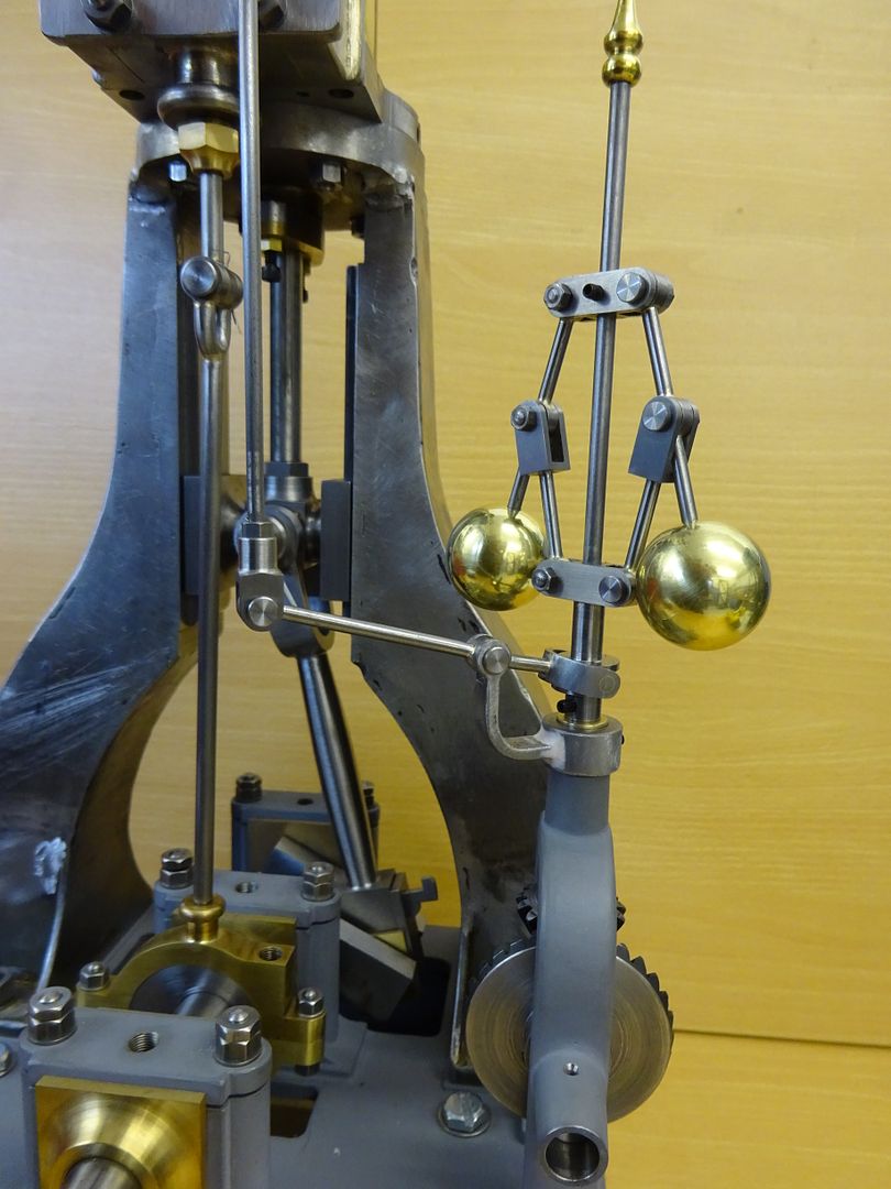
25215 forum posts 3105 photos 1 articles | Now that I have polished up my balls I feel happy to show them in public, also got the various pivots, levers and links done that transfer the novement of the governor up to teh butterfly valve on the valve chest.
|
| Ian S C | 14/12/2015 12:19:47 |
 7468 forum posts 230 photos | That's a fine pair of balls you have there Jason, should be quite uplifting. Ian S C |
| JasonB | 16/12/2015 20:47:01 |
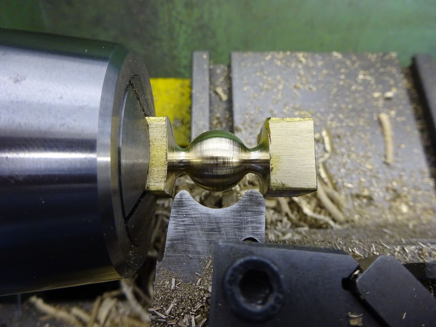
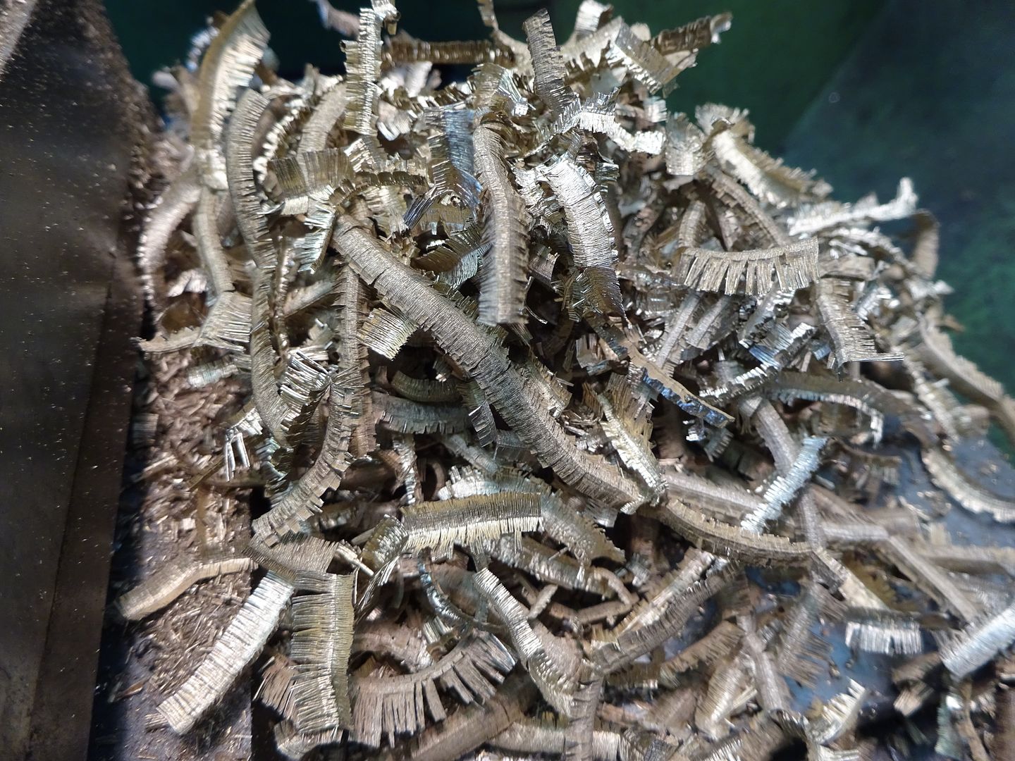
25215 forum posts 3105 photos 1 articles | Thanks Ian With the ball done it was time to make a start on my cocks, cut from 5/8 sq brass.
Plus a bonus photo for Andrew J
J |
| Ian S C | 17/12/2015 10:42:28 |
7468 forum posts 230 photos | Those balls would make good decorations for the Christmas Tree. Ian S C |


This thread is closed.
Magazine Locator
Want the latest issue of Model Engineer or Model Engineers' Workshop? Use our magazine locator links to find your nearest stockist!
Sign up to our Newsletter
Sign up to our newsletter and get a free digital issue.
You can unsubscribe at anytime. View our privacy policy at www.mortons.co.uk/privacy
Latest Forum Posts
- *Oct 2023: FORUM MIGRATION TIMELINE*
05/10/2023 07:57:11 - Making ER11 collet chuck
05/10/2023 07:56:24 - What did you do today? 2023
05/10/2023 07:25:01 - Orrery
05/10/2023 06:00:41 - Wera hand-tools
05/10/2023 05:47:07 - New member
05/10/2023 04:40:11 - Problems with external pot on at1 vfd
05/10/2023 00:06:32 - Drain plug
04/10/2023 23:36:17 - digi phase converter for 10 machines.....
04/10/2023 23:13:48 - Winter Storage Of Locomotives
04/10/2023 21:02:11 - More Latest Posts...
- View All Topics
Support Our Partners


Shopping Partners
Subscription Offer

Latest "For Sale" Ads
- Reeves** - Rebuilt Royal Scot by Martin Evans
by John Broughton
£300.00 - BRITANNIA 5" GAUGE James Perrier
by Jon Seabright 1
£2,500.00 - Drill Grinder - for restoration
by Nigel Graham 2
£0.00 - WARCO WM18 MILLING MACHINE
by Alex Chudley
£1,200.00 - MYFORD SUPER 7 LATHE
by Alex Chudley
£2,000.00 - More "For Sale" Ads...
Latest "Wanted" Ads
- D1-3 backplate
by Michael Horley
Price Not Specified - fixed steady for a Colchester bantam mark1 800
by George Jervis
Price Not Specified - lbsc pansy
by JACK SIDEBOTHAM
Price Not Specified - Pratt Burnerd multifit chuck key.
by Tim Riome
Price Not Specified - BANDSAW BLADE WELDER
by HUGH
Price Not Specified - More "Wanted" Ads...
Get In Touch!
Do you want to contact the Model Engineer and Model Engineers' Workshop team?
You can contact us by phone, mail or email about the magazines including becoming a contributor, submitting reader's letters or making queries about articles. You can also get in touch about this website, advertising or other general issues.
Click THIS LINK for full contact details.
For subscription issues please see THIS LINK.
Digital Back Issues


Donate

 Register
 Log-in
Model Engineer Magazine
- Percival Marshall
- M.E. History
- LittleLEC
- M.E. Clock

ME Workshop
- An Adcock
- & Shipley
- Horizontal
- Mill

Subscribe Now
- Great savings
- Delivered to your door

Pre-order your copy!
- Delivered to your doorstep!
- Free UK delivery!
All Forum Topics > Work In Progress and completed items > The Workshop Progress Thread