Forum sponsored by:

The Post Man Cometh.
James Coombes Engine
| Nick_G | 16/12/2014 21:45:10 |
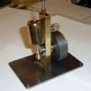
 1808 forum posts 744 photos | . Have done some work this eve on the valve, it's rod, cross bar and the jointing piece. But which way does the valve install. The way it is shown here or rotated 90 degrees.??
Cheers, Nick |
| JasonB | 17/12/2014 07:30:00 |
 25215 forum posts 3105 photos 1 articles | The 9/16 is the width and the 21/32 the height so looks like you have it the right way round, though I would turn it 180 degrees as the slot should be closer to the top edge than the bottom. |
| GaryM | 20/12/2014 00:22:44 |
 314 forum posts 44 photos | Hi Nick, Great progress so far. Re: valve orientation. I asked the same question when building my S50. See this thread Gary |
| Nick_G | 27/01/2015 01:11:10 |
1808 forum posts 744 photos | . OK guy's. Back on parade again now after a 'sabbatical' of decorating and tiling. So we jump onto the long awaited PCD holes associated with the cylinder and the ends that join onto it. I did a trial run on some scrap yesterday and this eve started with the most easily remade part if I made a dogs-danglers of it. So I first did the cylinder bottom / supporting plate.
With that done seemingly OK I next did the cylinder head. First spotting with a small center drill and then 7BA clearance holes.
I used a laser edge finder to find the center of each piece so that I could then punch the center into the DRO
7BA tapping size drill was then used on the cylinder head. - Nearly dropped a clanger as originally picked up the 7BA clearance drill. Fortunately I realised before it was too late.!
By this stage I am wondering if it will all fit.?
It does. .............. So no four letter words were required. ( not that they would have fixed it
So Nick goes to bed a happy-chappy tonight.
Nick |
| JasonB | 27/01/2015 07:35:29 |
25215 forum posts 3105 photos 1 articles | Looking good Nick and I like the way the hole positions are displayed as it gives you a visual check before you start drilling. |
| Michael Gilligan | 27/01/2015 07:57:45 |
 23121 forum posts 1360 photos | Nick
MichaelG. |
| Nick_G | 27/01/2015 12:51:17 |
1808 forum posts 744 photos | Posted by JasonB on 27/01/2015 07:35:29:
Looking good Nick and I like the way the hole positions are displayed as it gives you a visual check before you start drilling.
Yes. I found that very helpful. I could see that I had originally entered the wrong start and end angles. Taking that aside the menu on the unit is very intuitive. - I only had to read the manual once to do the PCD's
Nick |
| Nick_G | 30/01/2015 11:21:19 |
1808 forum posts 744 photos | . I know I am jumping ahead of the game here as the engine is not finished. But just thinking for the future. Would this **LINK** boiler be OK to run the James Coombes.
Thanks, Nick |
| Nick_G | 31/01/2015 02:52:20 |
1808 forum posts 744 photos | . I don't know if anybody else is the same when they return to a project. But after a month away from the engine I find I am having to get back into the swing and rhythm of what I was doing previously. I was never happy with the finish that I had upon the flywheel. It's accuracy I was happy with but I did not feel the surface was good enough to get a nice polish on. So I decided to reface it with the Eccentric engineering tool holder that I had purchased since the original machining. I did not fancy trying to dial in the 3/8" crankshaft bore back in on the faceplate so I decided to make a mandrill with a snug fit to the bore of the flywheel. I had some EN24 that I had liberated from a friends scrap bin so used that and cut a 10mm thread on the lathe to hold the flywheel secure.
Cuts of about 5 tho to all sides with a freshly sharpened tool gave a much sweeter surface that I should now be able to polish. Hope to be able to make some more progress into fresh areas this week end. Nick |
| JasonB | 31/01/2015 07:37:37 |
25215 forum posts 3105 photos 1 articles | Looking at my old Stuart catalogue when they also used to do boilers they suggest the No 504 for the James Combes and all the others that use the same cylinder. This was a 3.5" dia x 10" boiler so the PMR one would be around the same size. You can get them in the UK from Forrest Classics. There is a build diary of one on MEM which will give you a better idea of what they are like, and what mistakes to avoid, give me a while to track it down. J PS as the JC has a drive pully the flywheel would more than likely have had a painted flywheel rim |
| JasonB | 31/01/2015 08:00:17 |
25215 forum posts 3105 photos 1 articles | Here you go, don't spend all day reading it there is swarf to be made |
| Nick_G | 31/01/2015 11:33:56 |
1808 forum posts 744 photos | Posted by JasonB on 31/01/2015 08:00:17:
Here you go, don't spend all day reading it there is swarf to be made
Thanks for the information Jason. (once again Yup swarf to be made. I wonder if I could take power from motorbike to rotate my workshop machines. Now that would be a project.
Nick |
| Martin Cottrell | 31/01/2015 23:06:21 |
| 297 forum posts 18 photos | I wonder if I could take power from motorbike to rotate my workshop machines. Now that would be a project.
Nick Hi Nick, you're sounding more like Guy Martin than Valentino Rossi but that's no bad thing!! Martin. |
| Nick_G | 01/02/2015 16:13:37 |
1808 forum posts 744 photos | Hi Nick, you're sounding more like Guy Martin than Valentino Rossi but that's no bad thing!! Martin.
My likeness to Rossi ends usually within 100 yards of me setting off and realising what speed I am doing. This is then followed by me chopping the throttle well before the first corner so I can go round it at the same speed my grandmother would have. Anyway, back to the build. Today I drilled and fitted the crosshead guides.
I then have made a start on the cross heads.
. After I finish the cross heads I will move onto the con rod. On the James Coombes this is a 'Y' shaped affair. This by the look of it will probably be a none too easy exercise for a newbie like me so any tips will be welcome.
Nick |
| Nick_G | 02/02/2015 21:03:17 |
1808 forum posts 744 photos | . This eve I finished the cross head and decided to call it a night. Busy Monday and tired so doing more would be asking for a cock up.
Nick |
| NJH | 02/02/2015 22:06:17 |
 2314 forum posts 139 photos | Very wise Nick - I have a few bits in y scrap bin where I should have left we'll alone until the next day.
Norman
|
| Nick_G | 03/02/2015 09:21:50 |
1808 forum posts 744 photos | Posted by NJH on 02/02/2015 22:06:17:
Very wise Nick - I have a few bits in y scrap bin where I should have left we'll alone until the next day.
Norman
I think most of us have found out the hard way on that one. I know I have.!
Nick |
| Nick_G | 09/02/2015 18:39:30 |
1808 forum posts 744 photos | . Bit of advice please guys. I need to make the conrod. Which on the James Coombes is a Y shaped affair. Like most engines of this type its a highly visual part of the engine. So in addition to it being the correct size and not distorted in any direction it has to look 'pretty' I need to make this :-
Out of this :-
What's the best way to go about it do we think.?
Cheers, Nick |
| JasonB | 09/02/2015 18:57:51 |
25215 forum posts 3105 photos 1 articles | I would get the holes in the ends of the two main rods early on while they are still square. So square off the ends leaving as long as possible, centre drill one end. Then hold in teh mill vice, use an edge finder to locate the undrilled end the and zero your dro, find center across the bar and zero the other axis. Measure in half the radius which I can't quite see and drill & ream the 1/8" hole. Move down 6 9/16" then drill and ream that hole. Repeat for the other rod/ You can now hold in the 4-jaw by the little end with ctr support in teh other to turn the fish belly, then shape the ends which will remove the ctr hole. Cross piece is basic turning, I would drill & ream a cross hole 3/16" dia and counter bore a little way 1/4", don't debur the 3/16" hole. Big end is again turning in the 4-jaw, its not dimensioned but tahe the round part down to 1/4" to fit teh counter bore and then form a 3/16" stub on the end. Test assemble to get the location of the big end hole, drill & ream then file or mill the rounded end. Fit the big end to the cross piece with loctite, when dry add a pin with a bit of loctite. Then add the two long pieces again with loctite and pin when dry. don't debut the pin holes. All assembly on a flat surface. Once all the loctite has dried file off the ends of the pins and the projecting 3/16" spigot, you should hardly see the joints. J PS if you don't know how to do the fish belly ask. |
| NJH | 09/02/2015 19:05:32 |
2314 forum posts 139 photos | Nick I've not built this myself but have been tempted from time to time! The best source of information * I've found on Stuart models are the books by Andrew Smith - in this case "Building the James Coombes Table Engine. I don't know if they are still available but it's worth an internet search or, indeed, do Stuart Turner sell them? I'm assuming that it is the long tapered connecting rods that is your concern? A.S. centre drills the ends of each long square piece and then machines between centres. This allows work to be taken out and reversed to facilitate the production of the tapers - finishing, I guess, with a fine file to blend them together. Norman * PS. Alternatively, having seen Jason's authoritative advice since I posted, listen to him! N
Edited By NJH on 09/02/2015 19:26:24 |


Please login to post a reply.
Magazine Locator
Want the latest issue of Model Engineer or Model Engineers' Workshop? Use our magazine locator links to find your nearest stockist!
Sign up to our Newsletter
Sign up to our newsletter and get a free digital issue.
You can unsubscribe at anytime. View our privacy policy at www.mortons.co.uk/privacy
Latest Forum Posts
- hemingway ball turner
04/07/2025 14:40:26 - *Oct 2023: FORUM MIGRATION TIMELINE*
05/10/2023 07:57:11 - Making ER11 collet chuck
05/10/2023 07:56:24 - What did you do today? 2023
05/10/2023 07:25:01 - Orrery
05/10/2023 06:00:41 - Wera hand-tools
05/10/2023 05:47:07 - New member
05/10/2023 04:40:11 - Problems with external pot on at1 vfd
05/10/2023 00:06:32 - Drain plug
04/10/2023 23:36:17 - digi phase converter for 10 machines.....
04/10/2023 23:13:48 - More Latest Posts...
- View All Topics
Support Our Partners


Shopping Partners
Subscription Offer

Latest "For Sale" Ads
- Reeves** - Rebuilt Royal Scot by Martin Evans
by John Broughton
£300.00 - BRITANNIA 5" GAUGE James Perrier
by Jon Seabright 1
£2,500.00 - Drill Grinder - for restoration
by Nigel Graham 2
£0.00 - WARCO WM18 MILLING MACHINE
by Alex Chudley
£1,200.00 - MYFORD SUPER 7 LATHE
by Alex Chudley
£2,000.00 - More "For Sale" Ads...
Latest "Wanted" Ads
- D1-3 backplate
by Michael Horley
Price Not Specified - fixed steady for a Colchester bantam mark1 800
by George Jervis
Price Not Specified - lbsc pansy
by JACK SIDEBOTHAM
Price Not Specified - Pratt Burnerd multifit chuck key.
by Tim Riome
Price Not Specified - BANDSAW BLADE WELDER
by HUGH
Price Not Specified - More "Wanted" Ads...
Get In Touch!
Do you want to contact the Model Engineer and Model Engineers' Workshop team?
You can contact us by phone, mail or email about the magazines including becoming a contributor, submitting reader's letters or making queries about articles. You can also get in touch about this website, advertising or other general issues.
Click THIS LINK for full contact details.
For subscription issues please see THIS LINK.
Digital Back Issues


Donate

 Register
 Log-in
Model Engineer Magazine
- Percival Marshall
- M.E. History
- LittleLEC
- M.E. Clock

ME Workshop
- An Adcock
- & Shipley
- Horizontal
- Mill

Subscribe Now
- Great savings
- Delivered to your door

Pre-order your copy!
- Delivered to your doorstep!
- Free UK delivery!
All Forum Topics > Work In Progress and completed items > The Post Man Cometh.