Forum sponsored by:

New technology in Model Engineers Workshop
The way forward.
| Clive Hartland | 22/05/2011 18:43:50 |
 2929 forum posts 41 photos | John, I have done several reinforced concrete casts for use as Collimator stands.
In these the threaded fixings were normal brass grouts and were bolted up to the plywood form before filling. We greased the threads before starting.
I agree about the heat from the setting mix, the form got quite hot to the touch.
In two places we placed metal plates against the inside of the plywood to ensure a completely flat surface on the cast concrete.
When set and the plywood was removed they were a three man lift to move.
When the collimators were set up there was no movement of the bubbles at all.
Good luck on your casting!
Clive |
| John McNamara | 30/05/2011 17:17:32 |
 1377 forum posts 133 photos | Hi All Update on Worden…Epoxy concrete base poured Formwork As seen in the photos a sheet of Melamine MDF board was used as a base to build an enclosing framework 50mm high. A number of simple steel angles were used to join the framework to the base, and to hold the corners in place. Note the quarter round plastic insert at the bottom of the mould. The drawings show this to be a 45 degree arris however a suitable moulding was not available. Therefore a substitute was made; 10mm tile bull nose strip, a length cost $6.00 in Australia. After mitering the corners on the drop saw, the long edge that normally goes under the tile was slipped under the edge of the framework to hold them in position. The frame was built over a 1:1 drawing printed on an AO sheet of plain paper, placed on the base board. I have a plan plotter. The positions of the screwed inserts were punched through the plan to mark the backing board. This method is fine where the accuracy does not have to be better than about .25mm. Otherwise the holes could be marked out by hand. The screw inserts are M8 left over from another job. They are actually threaded on the outside as well to be screwed into MDF cabinet maker’s suppliers have them. As they are a bit short I used two on each M8 bolt screwed in from the back of the board and tightened securely to be removed later. The ends of the inserts were sealed to stop the epoxy from seeping into the thread and locking it. If these inserts were not available I would have made them from mild steel rod. By drilling and tapping M8 and grooving the outside diameter to give a key for the epoxy. 12mm deformed concrete reinforcing bar was used for reinforcement I tied the bars to the inserts prior to pouring. A little overkill bit it was in stock. 8mm deformed bar would have been fine. Once complete a “Gel coat” was brushed on to the base and the inside sides. This coat comprised “Megapoxy HICB” a product normally used in mining in rock crushers! It contains fine silica for added strength and is a bluish colour. To dye it grey I added 4 teaspoons of graphite powder this turned it a black grey colour about 300mls was used. As I am experimenting with both HICB and plain epoxy I had it to hand, it would be just as good to use plain Megapoxy H. 7mm screened quartz river sand was used as the aggregate, visual inspection reveals it to be about 70% quartz to this I added 25% by volume fine washed sand. Both the sand and the aggregate was heated to 200 degrees Centigrade to dry it, A slow process you have to spread it out on trays about 3cm max thick. Otherwise the moisture just stays in the lower levels Cont Next Post Edited By John McNamara on 30/05/2011 17:33:15 |
| John McNamara | 30/05/2011 17:20:08 |
1377 forum posts 133 photos | The 25% ratio for the sand was calculated filling a 810 ml tin plated food can right to the top with aggregate (Which was then carefully weighed) placing a large gear over it and introducing sand into the hole in the gear while wrapping it all around the sides with a light metal bar, until the mix started coming up the hole, At which point the can was tipped into a bucket and stirred, The mix put back in the can and the process started over until I could get no more in. A process that took about an hour to complete but it only has to be done once (Unless you change one of the materials). The Idea is to fill all the voids between the aggregate with sand. The last step is to weigh the sand aggregate mix you just created subtract the weight of the aggregate which gives the weight of the sand needed. By carefully weighing out that quantity of sand and placing it in the same tin you can measure the height. In this test it was a quarter of the can. 25%. I calculated the base 500x350x50 to have a volume of 8.75 Litres Using the food can I mixed as follows 10 x 810ml cans of aggregate 2.5 x 801ml cans of sand As per our findings above we have a volume of 10 x 810 cans = 8.10 litres of aggregate mix; the sand was absorbed. For the aggregate mix Megapoxy H was used this is a clear liquid and the hardener is similar. (I believe it may be Available in the UK I found a site on the net) 810 ml of epoxy 270ml of hardener was used meaning that our base is about 13% by volume epoxy. Not bad for a first test. After the pour was finished visual inspection revealed it may be possible to increase the sand a little. I will also try a little less epoxy next time with an objective of sub 10% epoxy. Less epoxy should result in stiffer deflection properties. Yes it will also save a little expense but that is not the objective here. The actual mixing was simple and quick. The epoxy and hardener first in a small container, they must be carefully measured and very well mixed. For mixing the aggregate two 20 Litre pails were used. The aggregate and sand was placed in the first pail then tipped into the second this process was repeated until the sand and aggregate was mixed, then the Epoxy mix was gradually added and the tipping form one bucket to the other was continued until a homogeneous mass was obtained; in about ten minutes we were ready to pour. When poured out the epoxy had evenly coated the aggregate and sand, it tipped out of the bucket quite cleanly leaving little residue on the sides. This is a good method for small quantities. The mix was poured into the mould and manipulated around the reinforcement steel and rammed down. I was lucky to have a small electric vibrator to assist in packing the material down. Otherwise a small tamper could be used to pack it down, when nearly finished I used a metal screed to level any high spots. The calculated mix was exactly the right amount! That does not happen very often. The finished surface of the aggregate was a little rough for my liking. Therefore I finished off with a coat of the Gel coat material used previously. The Epoxy sets in 24 hours and is full hard in a week. As soon as it hardens and the mould is stripped I will post a photo. The next step is the end plates and motor support. Cheers John McNamara Cont Next Post Edited By John McNamara on 30/05/2011 17:21:28 |
| John McNamara | 30/05/2011 17:31:28 |
1377 forum posts 133 photos | Base 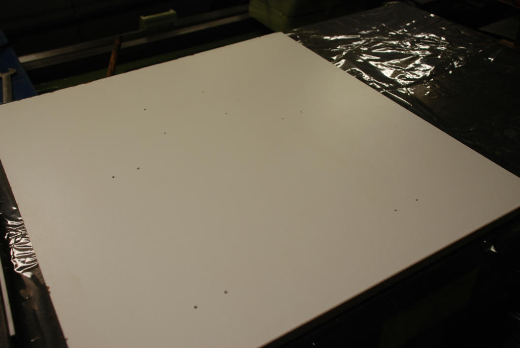 Marked out 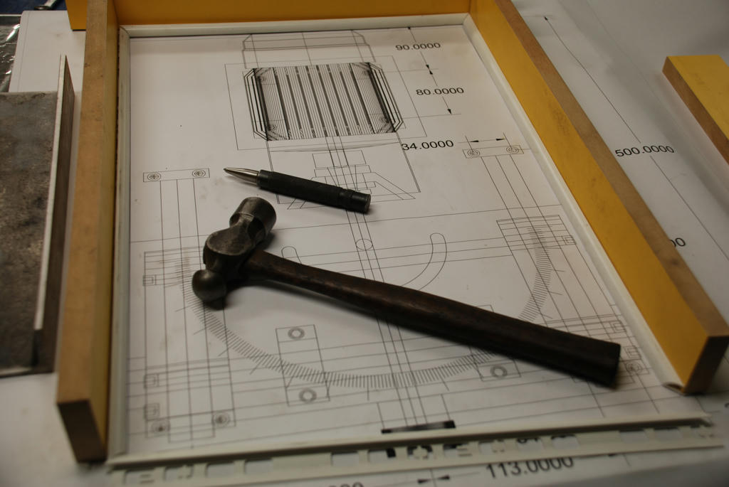 Inserts and rio 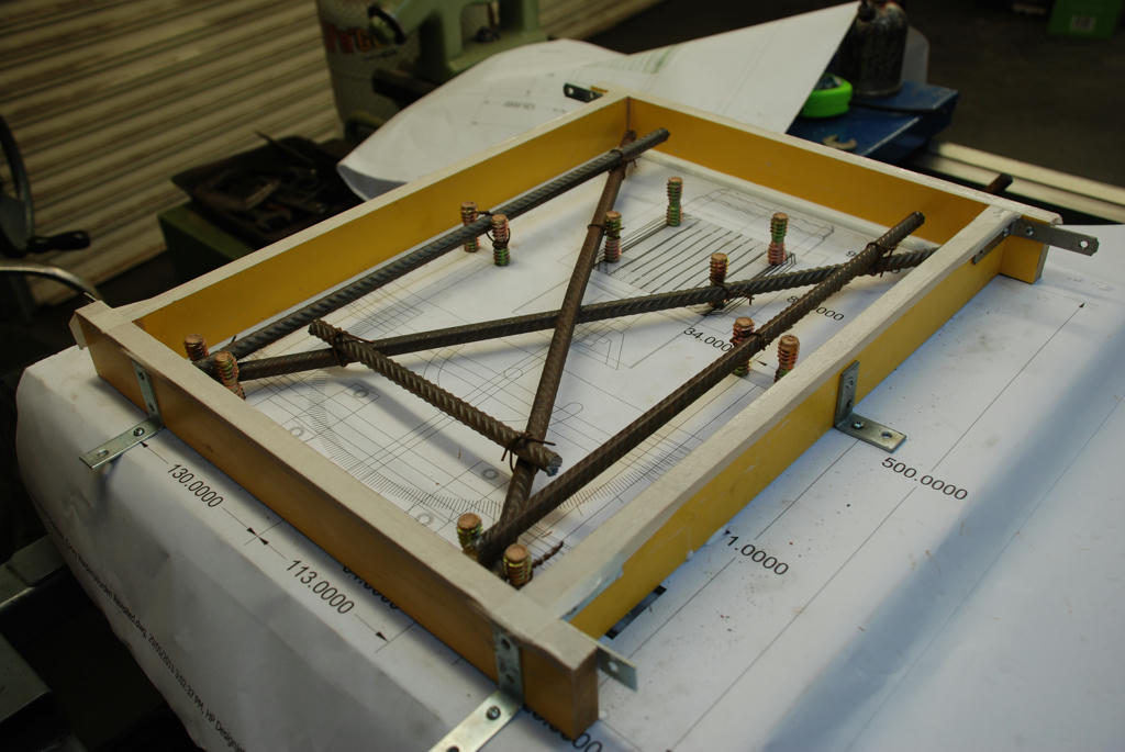 Aggregate 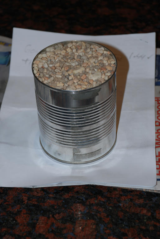 Add sand 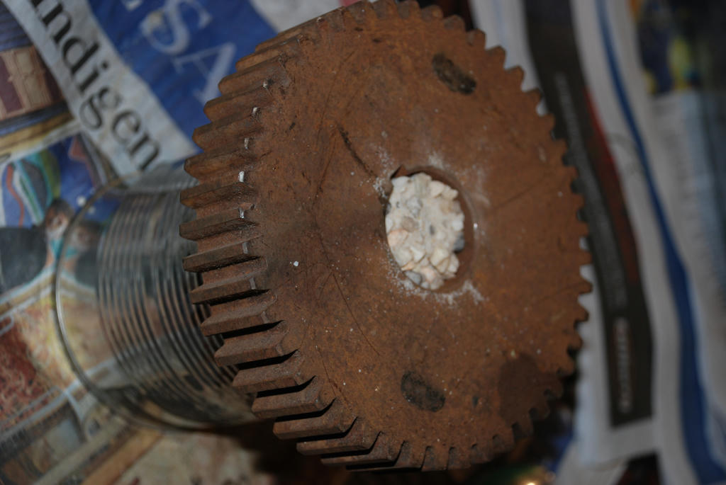 Gel coat 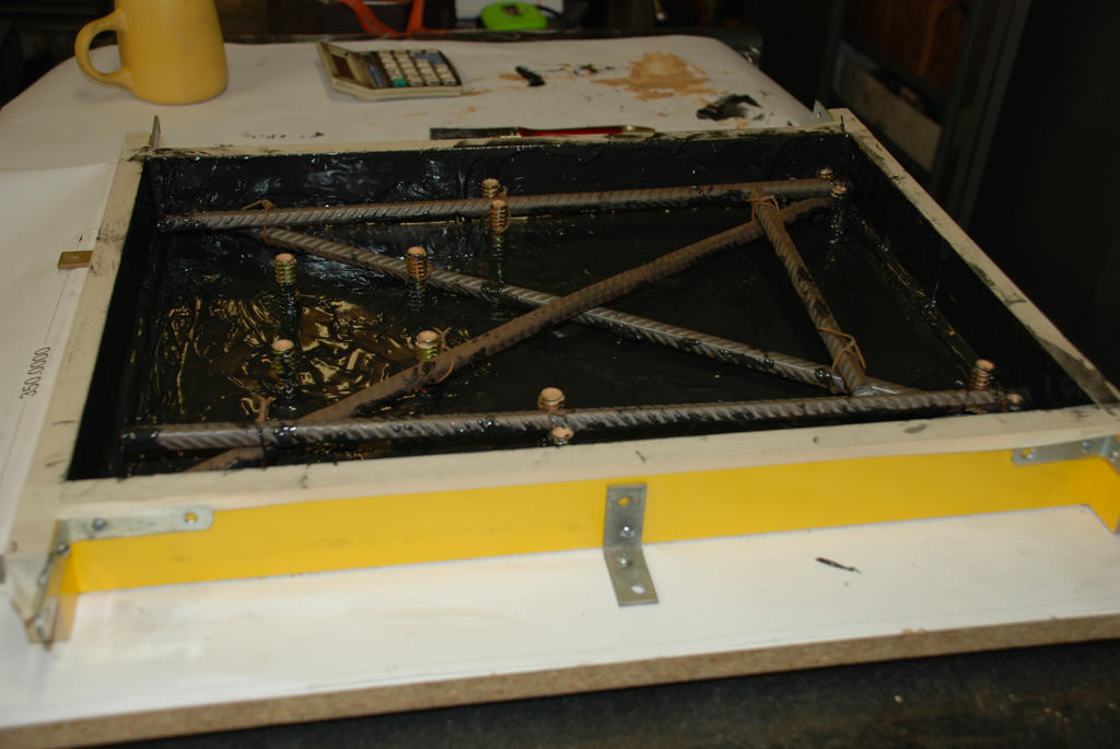 Pour aggregate 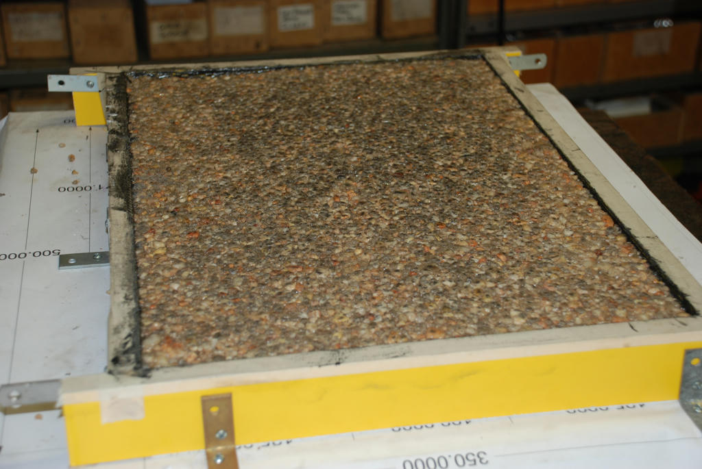 Finish coat on bottom 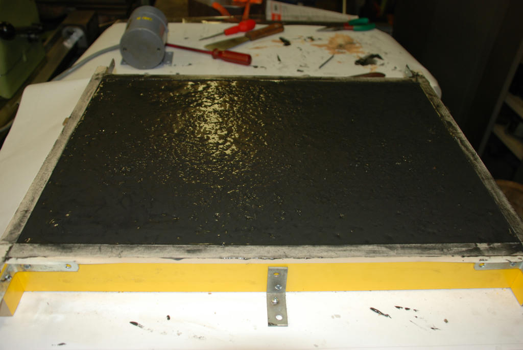 I will post the finished result in a couple of days Cheers John |
| John Stevenson | 30/05/2011 19:26:09 |
 5068 forum posts 3 photos | Why does all the commercial epoxy I have seen look like a fine granite slab and all the do it yourself stuff look like a paving slab ? John S. |
| Clive Hartland | 30/05/2011 21:40:52 |
2929 forum posts 41 photos | Because its machine polished, big rotating discs swilled with water and abrasive are run backwards and forwards over the surface.
Some times slabs are cut from the solid material with big carbide teethed saws.
Clive |
| John Stevenson | 30/05/2011 21:57:53 |
5068 forum posts 3 photos | Some of the parts I am speaking about are cast columns integral with their bases, much like a Bridgeport mill body. These are as cast and could not be cut and polished because of their shape. None of the aggregate seems as course as what the home shop guys use. Just wondering what the differences are and why what is used commercially can't be used in the home shop ? John S. |
| Terryd | 30/05/2011 22:44:40 |
 1946 forum posts 179 photos | Posted by John McNamara on 21/05/2011 18:03:29: Hi All ...................... Hi John, This sounds like an interesting process which has lots of possibilities. However, not being familiar with this particular composite material I am rather at a loss to understand why the larger aggregate should be "ideally rounded pebbles". In traditional Portland cement concrete the aggregate is deliberately cracked in order to provide interlocking interstices to give added strength and reduce cracking in the final concrete. It would seem that "rounded pebbles" provide no strength to the final mixture, merely providing a bulking material. Is there a reason for this with the process you are describing? Also in another post you say that aluminium casting needs 5 to 10 mm of extra material for machining rough castings. I must protest. I have made very many aluminium castings over the years and if a good sand and properly prepared pattern is used with proper finishing of the mould I find that there is very little roughness on the surface of the castings, in fact many non dimensionally critical castings are often just polished. Even when machined components are to be produced I only ever leave around a millimetre or so for the final skim as there is little distortion due to internal stresses compared with Iron castings if care is taken to allow proper cooling before removal from moulding flask. I would like to try epoxy cold casting as I can see the advantages, but I also think that perhaps a bit of practice to refine traditional techniques as well for some folk would not go amiss. Regards Terry |
| John McNamara | 31/05/2011 03:57:10 |
1377 forum posts 133 photos | Hi All Hi John Stevenson The base was cast upside down hopefully the top which is now the bottom will have a smooth surface. For this test I applied a gel coat first to hopefully get a fine finish. The sides were stripped this morning; I found that the gel coat does give a good finish. Lamentably there are a few flaws where the aggregate has disturbed the coating. Not really a problem as I intend to paint the casting anyway. A bit of Epoxy patch will fix the blemishes. Next time I will leave the gel coat longer time to set, before pouring the aggregate mix. My biggest issue is getting the right release agent. I had thought that the mould may not survive the pour. I was right, sides stuck in places and I had to chisel them off. I used PVA glue diluted with water as a mould release. Surprisingly this was recommended by a fiberglass boat builder who uses it commercially. It worked very well (Where it worked) I suspect the problem is that the gel coat was applied by brush. It is very thick; I may have removed some of the release agent in applying it. Ideally the release and gel coat should be sprayed on. Today I will try to source a non silicone commercial product. I want to paint the casting, silicone will make that very difficult. On the aggregate: Inspection of the areas where the gel coat was damaged suggests that more sand will be required. However this base is very sturdy rock solid in fact…. it will be fine for the Worden. Hi Terryd The gravel used was 7mm screened and washed river sand, hence the rounding. 8 dollars a bag from a local supplier, the 7mm gage is about the average of aggregate used by the many papers I have read as background for this project. Some papers also refer to rounded pebbles. I have also located a quarry about 100km away that mines granite and supplies 5mm sharp crushed material. Sand alone would be ideal for small items. I will be using sand for the Worden end plate castings. There will be no cracking. Once set the epoxy is almost inert. Few solvents will touch it. This is where Portland cement fails in this application. It continues to shrink over many years and you will get cracking. Re casting accuracy: I was referring to conventionally moulded cast iron not Aluminium castings, by conventional I mean greensand castings. Of course today we could also use the lost wax process or a number of others, for large cast objects almost impossible in the home workshop. Hi Clive yes I want one of those grinders! My findings so far: This process works. The mould release issue needs to be settled as does the so called ideal aggregate mix. However as is, I now have an almost finished base with all fixings in place; a bit of patch and paint and it is done. When hit with a hammer all I get is a dull clink. The vibration damping is superb. The epoxy sets hard in 24 hours and can be handled; it does not develop full strength for a week. I plan to check the base for deflection by loading it up on the surface plate after the 7 days has elapsed. In the mean time there is the end plate castings to work on. Cheers John |
| John McNamara | 31/05/2011 16:40:48 |
1377 forum posts 133 photos | Hi all I stripped the rest of form work today, it came out cleanly, with a few blemishes now patched with epoxy filler it is ready to paint. The PVC tile bull nose strip that was used to create the edge detail did not stick to the epoxy and was saved. The detail is only there for aesthetic reasons, it does make the base look a lot more interesting than just a rectangular chunk. Next time I am going to use a different formula for the gel coat Using the much thinner Megapoxy H spayed on. to avoid disturbing the release coat. First the M8 bolts that held the inserts in position while casting were removed. 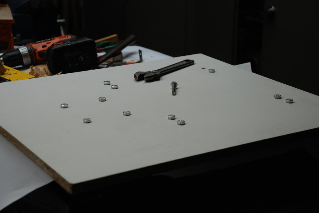 After patching... a good rub down with wet and dry paper and water. 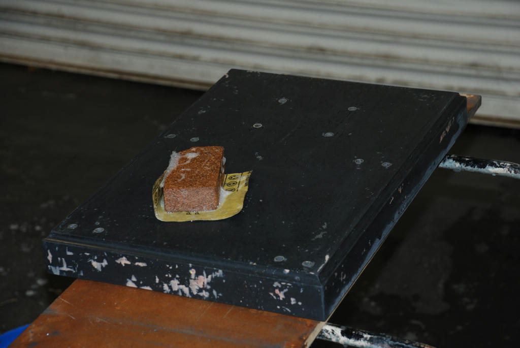 A quick test for flatness, very pleasing The base was cast on a piece of melamine coated MDF that was sitting on my surface plate on parallel cleats to clear the machine screw heads. about .002 inch error under the straight edge. There will be no problem setting up the rails. Note the inserts half covered by the straight edge.  Now it is ready to paint  Cheers John McNamara Edited By John McNamara on 31/05/2011 16:51:08 |
| KWIL | 31/05/2011 19:08:43 |
| 3681 forum posts 70 photos | John M, With all the griping about new technology or absence of it, why the waste of Forum space and not an article submitted for publication to a wider audience? |
| Hugh Gilhespie | 31/05/2011 21:00:01 |
| 130 forum posts 45 photos | 'John M, With all the griping about new technology or absence of it, why the waste of Forum space and not an article submitted for publication to a wider audience?'
Hmm - Well for me, I am enjoying this posting very much. It is very refreshing to see someone trying new techniques and documenting the results very well. Surely this is exactly the sort of thing that should be encouraged on this forum. Just my twopennorth.
Regards, Hugh |
| John McNamara | 01/06/2011 02:58:24 |
1377 forum posts 133 photos |
Hi All Hi Kwil I have considered preparing an article for the magazine; maybe in the future. Posting live has the advantage of spontaneity; you are not tied to a publication date and the inevitable delay before the article hits the reader. Every day I discover an issue that must be overcome, or a new idea to improve the work comes to mind. I know there are others following this thread over 3000 reads so far, very humbling and encouraging; it inspires me to do better. Hopefully a few readers will be encouraged to try the process, and share their findings. Hi Hugh Gilhespie Cheers John McNamara
Edited By John McNamara on 01/06/2011 03:02:41 Edited By John McNamara on 01/06/2011 03:03:03 Edited By John McNamara on 01/06/2011 03:03:15 Edited By John McNamara on 01/06/2011 03:03:49 |
| John Stevenson | 01/06/2011 06:58:34 |
5068 forum posts 3 photos | Thank you John M, I for one am also following this with interest, my questions are genuine questions of interest. The 3,000 reads also proves that there is an interest in new technology. One thing that came to mind is that my nephew is into kitchen and bathroom fitting and I have scrounged offcuts of very thick 50mm or so worktop that has the same melamine finish for work benches and shelves. I would image that that is also very stable as a base for larger projects. Another thing is or local garden centre also stocks all fancy aggregate for paths and beds, some of this is quite small, 5mm or so and in a lot of cases sharp which I'm sure would be better then the smooth pebbles as mentioned before. I look forward to the next instalment. John S. |
| John McNamara | 01/06/2011 16:20:11 |
1377 forum posts 133 photos | Hi John S It is not easy to get a definitive answer to the properties of MDF In your case laminated both sides with melamine or the like. I think the issue here is the deflection properties of MDF not the yield (Breaking) strength. I am sure you could place your bench top pieces between two supports and jump on them without breaking them. (Don't try it just in case) As is often the case in machine design it is deflection not strength that determines selection of the appropriate section. For each application you have to determine the accuracy you require. Damping is another issue. will there be any resonance effects, or vibration. particularly from a low density material like MDF. The link below shows MDF to have a Young's modulus of 4 GPa Aluminium 69GPa Steel 200 GPa The lower the number the greater the deflection will be. Check the properties of other materials too. An excellent tool that only costs 14 euros is MITcalc for simple beams. for non Structural engineers (Like me) very useful indeed. It is a simple spreadsheet that graphs deflection and yield, for many different materials and many commonly available sections or you can define your own. It takes about an hour or two to become fluent with it. Note how it shows results in red where the material properties are exceeded. As a caveat while you can use it for beams used in building construction, it is not a replacement for a qualified engineer where human safety is involved. I agree re the aggregate. Particularly if there is a clean and (Dry) local source. From my reading most are using granite or quartz. otherwise they use synthetics...Aluminium oxide Silicon carbide Etc. Cheers John M Edited By John McNamara on 01/06/2011 16:31:35 |
| John McNamara | 06/06/2011 08:44:08 |
1377 forum posts 133 photos | Hi All It’s been a while since I posted, a busy week here. The design has had a few modifications. Firstly the end support castings have been lengthened to 170mm and the location of the various shafts changed. Provision has been made to shift the table laterally a total of 70mm 35mm each way from centre. I plan to have a fine adjustment for the lateral position similar to the Quorn - this is yet to be finalised. I am wrestling with the table angle indicator, the difficulty being that if the table moves sideways the angle indicator should not. As shown below the clamping for the table is finalised; rather than using set screws that inevitably marr the shaft I have used self centering brass pincer collars. The outer one is threaded, the one closest to the knurled knob is not. Additionally I plan to make it possible to shift the motor to one side when the motor pillar is finalised, it appears likely that many times the edge of the wheel should be near the centre of pivot. I would be very interested to hear from MEW members who have built the Worden and use it. Is there ever a need to rotate the motor? The adjustment knobs for both X and y turn an M12 * 1.75 shaft. There are 70 divisions on the graduated sleeves. There should be 68.8976 divisions for exactly fo .001 inches per graduation mark. I rounded to 70 divisions because it divides by 70 and 10 for the graduation marks to cover one rotation of the shaft. The Y Axis thread should be reverse threaded to make it intuitive, easy enough to turn on the lathe. The nut (In the motor base), will be cast in epoxy so no problem making or sourcing a special tap. Making the end support castings Starting out with a flat base of melamine MDF, onto which a 1:1 printed copy of the side elevation plan for the parts was placed. this paper plan was then protected with “Baking film” a product suggested by my wife, it worked well : the epoxy did not stick to it. Using this layout, a simple tray mould to contain the mix was cut and aligned carefully with the plan, using 50mm strips of melamine coated MDF. This left the radiused corners. To form these, odd lengths of pipe I had to hand of the correct radius were used as formers. One was a little small so I wrapped a few layers of tape over it to bring it up to size. I also wrapped cling film around the pipes to stop them sticking to the epoxy body filler. It was a simple matter to fill the corner with quick setting body filler then press the former (pipe) into the corner and wedge it. Some material squeezed out. The top was trowled off. The material squeezed out along the sides was not touched. After about 15 minutes the mix was “gel” set (still soft). The formers were removed and it was a simple matter to remove the still soft excess material. The small corners were simply trowled with a piece of rod to form the 6mm radius. After an hour the inside of the mould frame was sanded ready for casting. I used PVA glue as a mould release applied neat, rubbing it in thoroughly with my finger, and when that was set I greased the sides as well. The base of the mould had already been protected as noted above. It was decided to cast the Y axis bearings in situ using the Epoxy bearing material I developed previously. Two pieces of rod cut to 170mm were tapped both ends to enable them to be carefully centered in the mould and clamped. Before the main cast these rods were greased and coated with bearing material. There is a difficulty here….The material tries to run off. I had to turn the casting for an hour before it started to gel. A heat gun would be handy here. It would reduce that time to 15 minutes or less. A fair amount of force was required to remove the rods when the cast was set. I used a handy socket and a piece of M8 threaded rod to break the initial grip, once started using a punch (being careful not to touch the bore), the rods were driven out. Upon inspection the bores are shiny. Currently we have a heavy push fit. I will ease the bores slightly for a light push fit. I am guessing about .0001 inches will do it. After the casting has fully hardened over the next week it can be done. Mild steel inserts were made from bar oddments I had to hand, Leaving a 60mm length sticking out of the chuck I skimmed the OD, center drilled, drilled 12.5mm, faced, grooved with the parting tool and parted off in one setting. There are 3 x 25mm and 1 by 35mm diameter inserts for each end casting. The 12mm holes were made to enable the inserts to be securely bolted in position. The next step will be to bore the inserts to the correct diameter on the mill. Cast mix 1620 ML of oven dried fine washed sand 600ml Megapoxy HICB, normally used in rotary rock crushers (it contains about 60% fine silica powder), therefore our mix contained approximately 16.21% epoxy by volume. A similar result could be obtained with plain epoxy and graded sand. The mix was a friable mass rather stiff. As shown in the photos we got a good casting with few blemishes. Not quite enough tamping to fill the voids that will need be attended to next time. Finishing As removed from the mould there were sharp corners and a few blemishes. A small hand grinder was used to remove the sharp corners and form the small radius edge abounding each side. It also made short work of tidying up any raised blemishes. The wheel used was a rather old flap wheel that had seen better days. Maybe this was an advantage as it was not as aggressive as a new wheel would be. There are a few blemishes that will be repaired prior to painting. Continued next post... Edited By John McNamara on 06/06/2011 08:45:13 |
| John McNamara | 06/06/2011 08:51:04 |
1377 forum posts 133 photos | ...From Previous post Overall a very satisfying result. Not only is the epoxy Wordon project on track The lessons learnt are inspiring….. This process can be used in many other applications. Cheers John McNamara View from Right 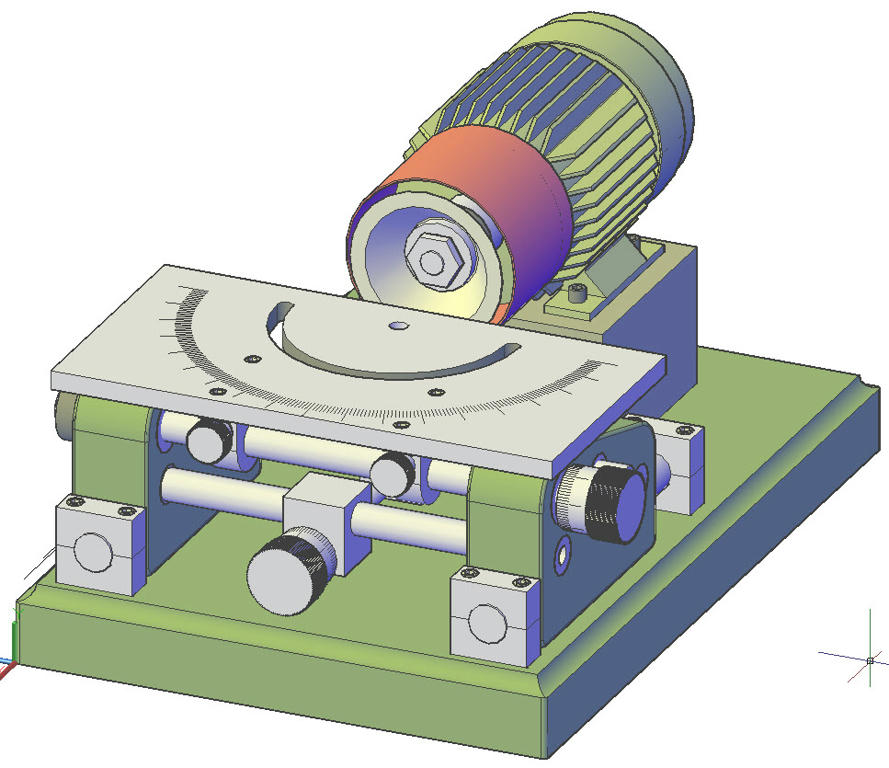 View from left 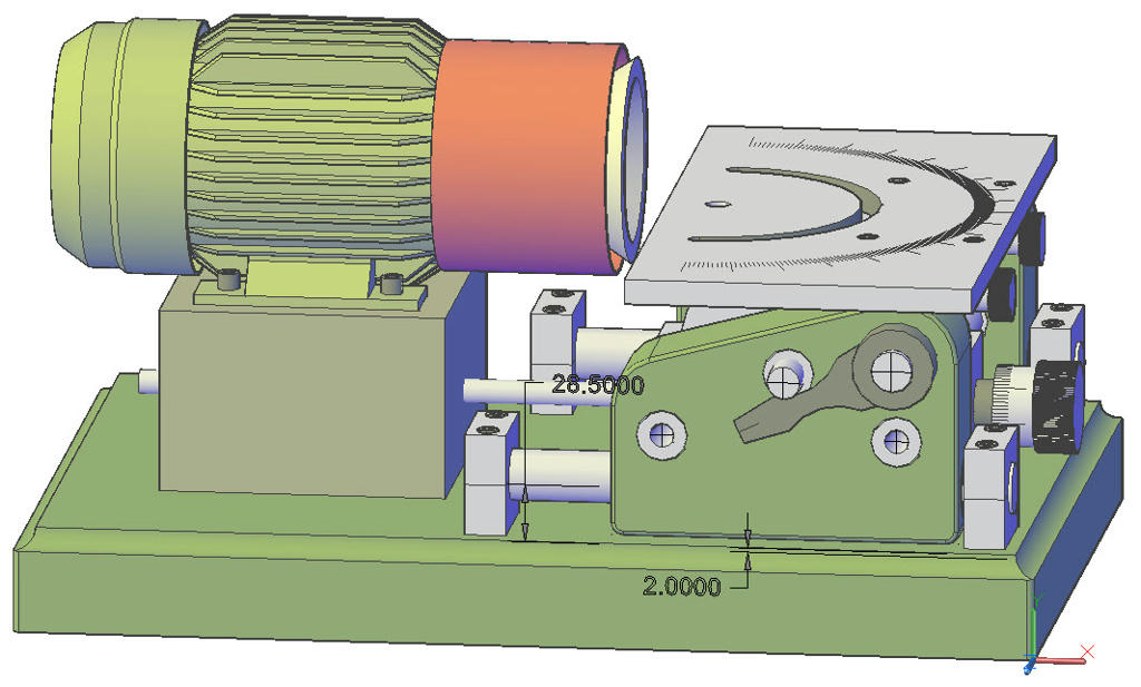 Table assembly view from below 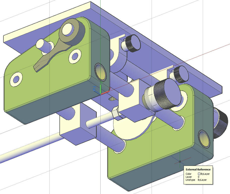 |
| John McNamara | 06/06/2011 09:07:18 |
1377 forum posts 133 photos | From previous post.... Table support Bracket 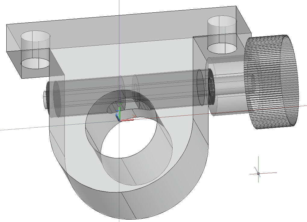 Frames made and corners formed. 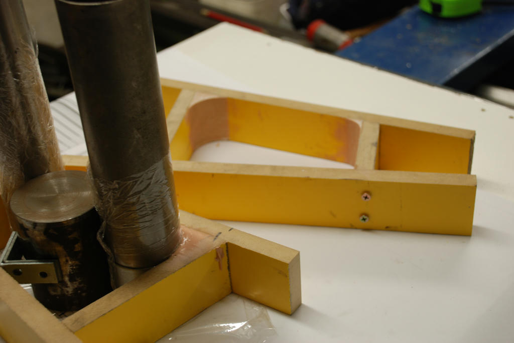 Inserts aligned with plan and bolted 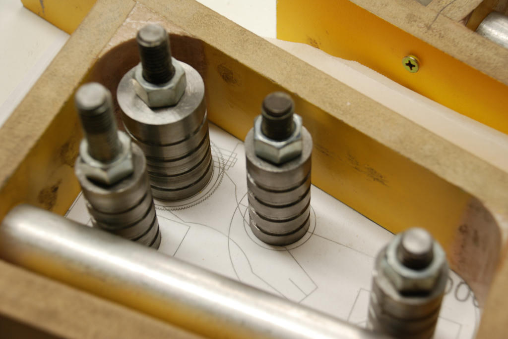 Epoxy Bearing material applied 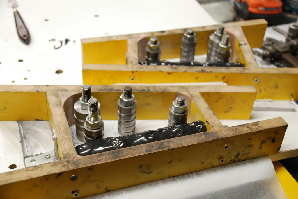 Main casting Poured  Formwork stripped 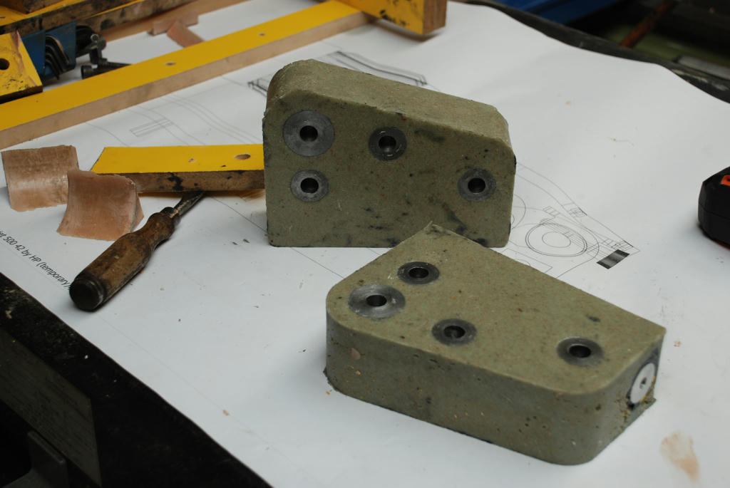 Continued next post.... Edited By John McNamara on 06/06/2011 09:08:09 |
| John McNamara | 06/06/2011 09:15:08 |
1377 forum posts 133 photos | ....From previous post Bearing former rod pulled 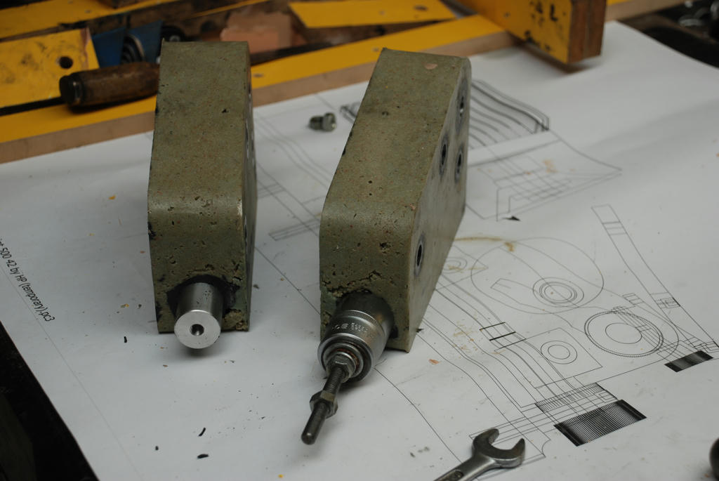 Bearing 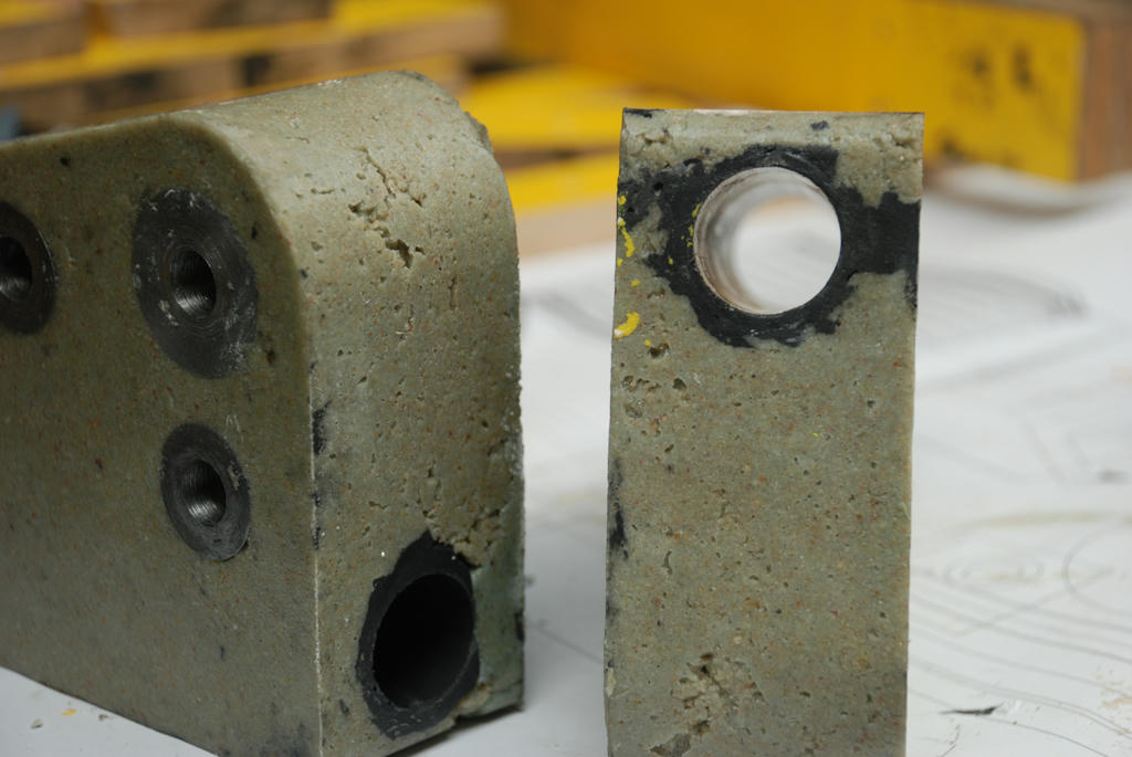 Edges and blemishes removed...We are ready to precision boring then paint. 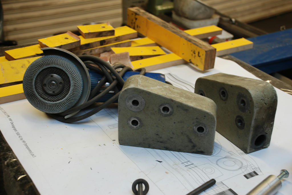 If a metal mould with precision located mountings for the inserts was made we would be ready to paint with out any further machining. Worth considering if many parts were to be made. Cheers John |
| Steve Garnett | 06/06/2011 10:05:46 |
| 837 forum posts 27 photos | Posted by Keith on 20/05/2011 13:31:41: I think that there may be a lot of truth in that. One of the things that has been noted in the past about the people who were truly innovative is that the vast majority of them had what could only be described as an 'unorthodox' education - in other words, they weren't at their formative stage shoved through a curriculum primarily intended to educate the masses, and one that only encourages certain types of rigid thought process. What this meant for people like James Watt (early education at home by his mother, didn't attend grammar school until much later) was that they could have 'what if' thoughts that weren't constrained by a load of stuff that they'd learned by rote and never questioned. If the only education that you feed to people is based on the present national curriculum, is it really any surprise that we have no innovators of the type we used to? So I don't think that it's quite the way ady described it, but I think he's pretty close when he says that Governments have interrupted the true course of Darwinism! Oh, and Darwin was another one with an unconventional educational background, as well. And there are loads more household names in the same category too. (I should also say that I'm not in the slightest trying to distract from John's very interesting posts - it's just that when I read through the earlier part of the thread, this bit stood out.)
Edited By Steve Garnett on 06/06/2011 10:08:33 |
Please login to post a reply.
Magazine Locator
Want the latest issue of Model Engineer or Model Engineers' Workshop? Use our magazine locator links to find your nearest stockist!
Sign up to our Newsletter
Sign up to our newsletter and get a free digital issue.
You can unsubscribe at anytime. View our privacy policy at www.mortons.co.uk/privacy
Latest Forum Posts
- *Oct 2023: FORUM MIGRATION TIMELINE*
05/10/2023 07:57:11 - Making ER11 collet chuck
05/10/2023 07:56:24 - What did you do today? 2023
05/10/2023 07:25:01 - Orrery
05/10/2023 06:00:41 - Wera hand-tools
05/10/2023 05:47:07 - New member
05/10/2023 04:40:11 - Problems with external pot on at1 vfd
05/10/2023 00:06:32 - Drain plug
04/10/2023 23:36:17 - digi phase converter for 10 machines.....
04/10/2023 23:13:48 - Winter Storage Of Locomotives
04/10/2023 21:02:11 - More Latest Posts...
- View All Topics
Support Our Partners


Shopping Partners
Subscription Offer

Latest "For Sale" Ads
- Reeves** - Rebuilt Royal Scot by Martin Evans
by John Broughton
£300.00 - BRITANNIA 5" GAUGE James Perrier
by Jon Seabright 1
£2,500.00 - Drill Grinder - for restoration
by Nigel Graham 2
£0.00 - WARCO WM18 MILLING MACHINE
by Alex Chudley
£1,200.00 - MYFORD SUPER 7 LATHE
by Alex Chudley
£2,000.00 - More "For Sale" Ads...
Latest "Wanted" Ads
- D1-3 backplate
by Michael Horley
Price Not Specified - fixed steady for a Colchester bantam mark1 800
by George Jervis
Price Not Specified - lbsc pansy
by JACK SIDEBOTHAM
Price Not Specified - Pratt Burnerd multifit chuck key.
by Tim Riome
Price Not Specified - BANDSAW BLADE WELDER
by HUGH
Price Not Specified - More "Wanted" Ads...
Get In Touch!
Do you want to contact the Model Engineer and Model Engineers' Workshop team?
You can contact us by phone, mail or email about the magazines including becoming a contributor, submitting reader's letters or making queries about articles. You can also get in touch about this website, advertising or other general issues.
Click THIS LINK for full contact details.
For subscription issues please see THIS LINK.
Digital Back Issues


Donate

 Register
 Log-in
Model Engineer Magazine
- Percival Marshall
- M.E. History
- LittleLEC
- M.E. Clock

ME Workshop
- An Adcock
- & Shipley
- Horizontal
- Mill

Subscribe Now
- Great savings
- Delivered to your door

Pre-order your copy!
- Delivered to your doorstep!
- Free UK delivery!
All Forum Topics > Model Engineers' Workshop. > New technology in Model Engineers Workshop