Forum sponsored by:

Lathe DRO
| Robin | 19/04/2021 23:36:19 |
 678 forum posts | My DRO shows X for saddle and Z for cross slide, but to change or set Z I have to press the Y buttons. I think they were as confused as me. When I first had it I mixed up the X and Y plugs causing weird readings because the Z is a 5 micron scale while the X is a 1 micron scale. Nothing about that in the manual. I rang up and asked how to get into the settings and change it but they didn't seem to know or didn't want to tell me. The answer was to hold down the ENTER key while turning it on at the plug. Where the cross slide DRO is fitted it removes 30mm travel from the tailstock which is fast running out of travel on the graduated part, whatever that calls itself. The nose? It cannot stay there, I am working on moving it. |
| JasonB | 20/04/2021 07:15:52 |
 25215 forum posts 3105 photos 1 articles | The reason for the 1micron scale on the cross slide is that as it measures radius your diameter could be double any error so 10micron if on the 5um scale was used. I think magnetic strip and a mini head from M-DRO under the cross slide like ChrisB is the way to go. As for how a scale could be mounted to the topslide, I would fit a piece of angle to the moving part, this could be fixed with a couple of M3 CSK screws and drilled to clear gib screws or you could make use of the locking nuts on the gib adjusters to hold it on. Stick tape to underside of angle. The head can be screwed to the side of the base or to a plate screwed to the underside. Whole thing sticks out no more than the gib screws and you are free to rotate and slide the topslide to where you want without having to alter mountings. Quick mock up, head is actually a bit flatter.
Also room for the 10mm x 12mm head at end of leadscrew (its longer than my block) and a cover/extension at the back again like ChrisB and JS did
|
| ChrisB | 20/04/2021 10:21:47 |
| 671 forum posts 212 photos | Had a look at the compound slide this morning and I can confirm what Jason says, that's the best place to install the read head. As to do the installation internally in the compound, it is impossible with off the shelf read heads. Posted by Robin on 19/04/2021 23:36:19:
Where the cross slide DRO is fitted it removes 30mm travel from the tailstock which is fast running out of travel on the graduated part, whatever that calls itself. The nose? It cannot stay there, I am working on moving it. That's why it's better to have the DRO installed under the crosslide if possible, but that depends on what type of read out you have, my guess is it will only work out with magnetic type due to their small size. |
| Robin | 20/04/2021 14:46:19 |
678 forum posts | My toolpost is much too wide. See how the top slide is angled back, but the tailstock still only has 1 cm extension left to go. 'tis a puzzlement.
|
| Tony Pratt 1 | 20/04/2021 15:02:05 |
| 2319 forum posts 13 photos | Same as my 290V, the cross slide is fairly wide any way & a DRO either side causes 'issues'. Just looked at a Emco Maximat lathe which the Warco lathes are I think clones of and the tail stock front has loads more over hang where the barrel is so you can get nearer the chuck with drills, centres etc. Tony Edited By Tony Pratt 1 on 20/04/2021 15:10:10 |
| ChrisB | 20/04/2021 19:17:10 |
| 671 forum posts 212 photos | This the closest the tailstock will ever come to the chuck on a WM280 lathe. Adding a dro to the right of the cross slide will only make it worse. You could mount the dro to the left, but that will expose the scales to oil, swarf and possibly impact damage. Mounting under the cross slide as Jason suggested will avoid all those issues and tailstock reach will be unchanged.
|
| JasonB | 20/04/2021 19:22:58 |
25215 forum posts 3105 photos 1 articles | Posted by ChrisB on 20/04/2021 19:17:10:
This the closest the tailstock will ever come to the chuck on a WM280 lathe. Unless it's an early model like mine where the carriage can move further to the right and touch the headstock
Not sure if a lack of stick out is classed as willy waving or not Edited By JasonB on 20/04/2021 19:28:19 |
| ChrisB | 20/04/2021 20:02:22 |
| 671 forum posts 212 photos | How come Jason! Mine won't go any further as the saddle will contact the feed shaft clutch. |
| JasonB | 20/04/2021 20:20:04 |
25215 forum posts 3105 photos 1 articles | Shear pin on mine. Also no Leadscrew spring cover or boxing sticking out the back where the motor goes. |
| Robin | 20/04/2021 20:58:26 |
678 forum posts | JasonB: Extending to the chuck is easy. The question is, can you extend the centre slightly past the tool tip ready to make that between centre cut and still have good support on the tailstock barrel? ChrisB: My saddle started hitting the feed clutch barrel as soon as I removed the clock spring from the lead screw. Luckily it hits an unused part of the split nut T slot so I can relieve it without emptying the oil from the apron. |
| Meunier | 20/04/2021 20:59:21 |
| 448 forum posts 8 photos | Posted by JasonB on 20/04/2021 19:22:58:
Posted by ChrisB on 20/04/2021 19:17:10:
where the carriage can move further to the right and touch the headstock Edited By JasonB on 20/04/2021 19:28:19 I think your right and left have become confused after SOD's tailstock episode. |
| JasonB | 21/04/2021 07:07:35 |
25215 forum posts 3105 photos 1 articles | Robin I mostly use a revolving ctr so that gives me extra length. Will take a photo later
|
| Robin | 21/04/2021 10:02:05 |
678 forum posts | I see the prices of the triple angle revolving centres are coming down at last. A credible alternative to the half dead centre? Perhaps an answer to the insert threading tool, set at 30 degrees, forcing a risky top slide extension below the chuck
Edit: Replacement picture, I got rid of most of the overhang but the tailstock is all the way out and the toolpost is blocking all but the fanciest of revolving centres... Edited By Robin on 21/04/2021 10:28:52 |
| Ian P | 21/04/2021 11:45:44 |
 2747 forum posts 123 photos | Forgive my ignorance, but what are 'triple angle revolving centres'? If prices are coming down, are they a better bet than Pork Bellies? IanP |
| Robin | 21/04/2021 11:59:25 |
678 forum posts | Ian P: I have no idea, I saw "8 Type Live Center Morse Turning Revolving Bearing MT2 MT3 Taper Triple" on e-Bay for £17.35 and took a wild guess. I meant the ones with the spindly nose that doesn't get in the way so much |
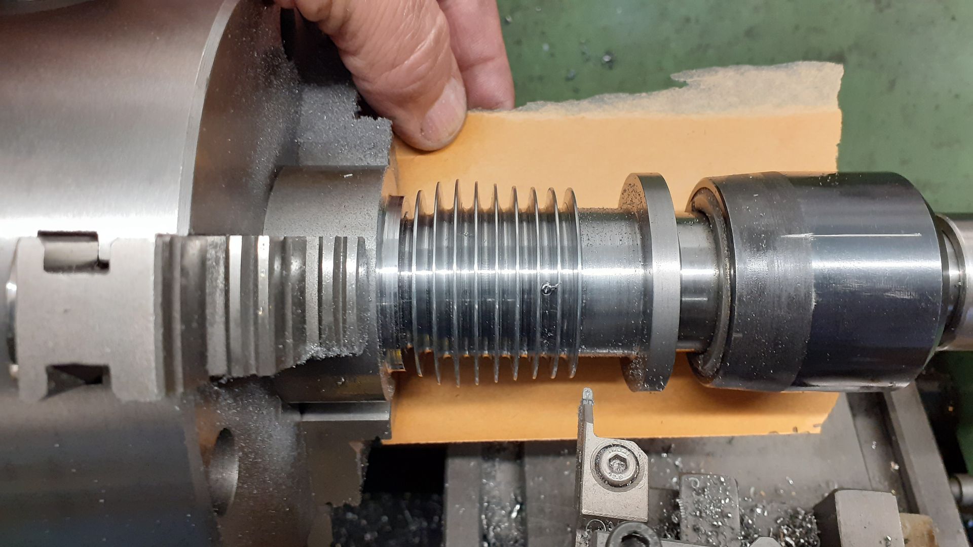
| JasonB | 21/04/2021 12:15:49 |
25215 forum posts 3105 photos 1 articles | Here you go
Standard revolving ctr, with the DCMY tool shown I can happily get down to 3.0mm dia for things like valve stems
Like this I can use the full travel of the topslide to give fine positioning when doing things like cutting a series of cylinder fins
reverting to the stock toolpost would reduce tailstock extension by another 12mm if needed.
|
| ChrisB | 21/04/2021 14:39:27 |
| 671 forum posts 212 photos | Posted by JasonB on 20/04/2021 20:20:04:
Shear pin on mine. Also no Leadscrew spring cover or boxing sticking out the back where the motor goes. You just got me my next project Jason! Some time back I got myself a lathe collet chuck, prepared a piece of steel for the backplate...bolted the blank backplate to the spindle and proceeded with the machining. Little did I know that the tool post would not reach the spindle! I managed, but it was one of those simple jobs turning into a nightmare. Spent the morning fiddling with the lathe, and result! I was wrong about the WM280 tailstock reach
|
| JasonB | 21/04/2021 15:40:49 |
25215 forum posts 3105 photos 1 articles | It's not just backplates when it helps but handy for faceplate work too. |
| ChrisB | 21/04/2021 18:08:03 |
| 671 forum posts 212 photos | Posted by JasonB on 21/04/2021 15:40:49:
It's not just backplates when it helps but handy for faceplate work too. True and also with the collet chuck, working close to the chuck I have to extend most of the topslide. And the issue with saddle travel would have been easy to fix at production level, the apron gearbox casting is already shaped quarter round to clear the feed shaft, they just needed to add 1/8" more to clear the clutch. I had no intention of removing the apron, so I turned down the clutch just enough to get some clearance. |
| Jim Smith 8 | 22/06/2021 19:55:37 |
| 29 forum posts 8 photos | I've got my scale working O.K now on the cross slide, but the standard size 150mm £30 scale had to be dismantled, electronics and wiring removed, then replaced after making it smaller. Then I found doing a simple turing and boring job the DRO numbers don't give the right answers I expected. It was after that I pushed the WM280V compound tool post hard towards the rear and heard a 'clunk' which measured about 0.65mm. It explained why my turning finish wasn't so good with more tooling marks than I expected. My final 20mm bore size calculated from a starting ID of 19mm and DRO readings divide/2 didn't work out. Now I know all about the compound X leadscrew and threaded block on these Chinese lathes and how when first assembled and set up 'wrongly' they can wear the LH Acme threaded brass block. I'll post some info later. I've now got the compound backlash down to 1/2 thou and no clunk. Turning a fine finish on some ali looks a lot better and I can turn a thou.off a 25mm bar reasonably confidently and repeatable for a cheap lathe. Edited By Jim Smith 8 on 22/06/2021 19:56:38 |
![20210419_133537[1].jpg](/sites/7/images/member_albums/44290/892686.jpg "20210419_133537[1].jpg")
![20210419_133725[1].jpg](/sites/7/images/member_albums/44290/892687.jpg "20210419_133725[1].jpg")


![20210421_081055[1].jpg](/sites/7/images/member_albums/44290/892770.jpg "20210421_081055[1].jpg")
![20210421_081319[1].jpg](/sites/7/images/member_albums/44290/892771.jpg "20210421_081319[1].jpg")
![20210421_081331[1].jpg](/sites/7/images/member_albums/44290/892772.jpg "20210421_081331[1].jpg")

Please login to post a reply.
Magazine Locator
Want the latest issue of Model Engineer or Model Engineers' Workshop? Use our magazine locator links to find your nearest stockist!
Sign up to our Newsletter
Sign up to our newsletter and get a free digital issue.
You can unsubscribe at anytime. View our privacy policy at www.mortons.co.uk/privacy
Latest Forum Posts
- *Oct 2023: FORUM MIGRATION TIMELINE*
05/10/2023 07:57:11 - Making ER11 collet chuck
05/10/2023 07:56:24 - What did you do today? 2023
05/10/2023 07:25:01 - Orrery
05/10/2023 06:00:41 - Wera hand-tools
05/10/2023 05:47:07 - New member
05/10/2023 04:40:11 - Problems with external pot on at1 vfd
05/10/2023 00:06:32 - Drain plug
04/10/2023 23:36:17 - digi phase converter for 10 machines.....
04/10/2023 23:13:48 - Winter Storage Of Locomotives
04/10/2023 21:02:11 - More Latest Posts...
- View All Topics
Support Our Partners


Shopping Partners
Subscription Offer

Latest "For Sale" Ads
- Reeves** - Rebuilt Royal Scot by Martin Evans
by John Broughton
£300.00 - BRITANNIA 5" GAUGE James Perrier
by Jon Seabright 1
£2,500.00 - Drill Grinder - for restoration
by Nigel Graham 2
£0.00 - WARCO WM18 MILLING MACHINE
by Alex Chudley
£1,200.00 - MYFORD SUPER 7 LATHE
by Alex Chudley
£2,000.00 - More "For Sale" Ads...
Latest "Wanted" Ads
- D1-3 backplate
by Michael Horley
Price Not Specified - fixed steady for a Colchester bantam mark1 800
by George Jervis
Price Not Specified - lbsc pansy
by JACK SIDEBOTHAM
Price Not Specified - Pratt Burnerd multifit chuck key.
by Tim Riome
Price Not Specified - BANDSAW BLADE WELDER
by HUGH
Price Not Specified - More "Wanted" Ads...
Get In Touch!
Do you want to contact the Model Engineer and Model Engineers' Workshop team?
You can contact us by phone, mail or email about the magazines including becoming a contributor, submitting reader's letters or making queries about articles. You can also get in touch about this website, advertising or other general issues.
Click THIS LINK for full contact details.
For subscription issues please see THIS LINK.
Digital Back Issues


Donate

 Register
 Log-in
Model Engineer Magazine
- Percival Marshall
- M.E. History
- LittleLEC
- M.E. Clock

ME Workshop
- An Adcock
- & Shipley
- Horizontal
- Mill

Subscribe Now
- Great savings
- Delivered to your door

Pre-order your copy!
- Delivered to your doorstep!
- Free UK delivery!
All Forum Topics > Beginners questions > Lathe DRO