Forum sponsored by:

Arduino Gear Hobber
| Tool | 29/07/2020 18:27:16 |
| 11 forum posts | There is a board that I use called a Teensy 4.1, it is programmed using the Arduino Ide. It is very easy to use and operates at 600MHz. I think it was less than £30. It has encoder inputs. Might be a contender? |
| SillyOldDuffer | 29/07/2020 18:34:13 |
| 10668 forum posts 2415 photos | For lovers of speed trials, I compared how fast Arduino, Nucleo and Raspberry can flip an output pin: Arduino Uno using digitalWrite() - 3.30uS pulse width (approx 150kHz) Nucleo F446RE and mbed DigitalOut with out = !out; - 0.15uS (approx 3.4MHz) RaspberryPi3B (Completely Fair Scheduler) - 0.042uS (approx 11.6MHz), with occasional jitter. Ought to explain Arduino's digitalWrite() is slow compared with absolute top speed because the function stops the programmer from making silly mistakes. Bit twiddling IO may be fast but it's hard to understand and easy to get horribly wrong. The DigitalIO library is a good compromise and similar to mbed's approach to IO. Anyway, without resorting to bit twiddling, a Nucleo can pulse 3 times faster than an Arduino, or 22 times faster if the Arduino programmer sticks to digitalRead() and digitalWrite(). This is a good thing! However, the RaspberryPi3B wins this simple contest - it's 3.6 times faster than a F446RE, and 83 times faster than Arduino's digitalWrite(). Speed writing isn't exactly a fair test of computers. Comparing power consumption, I'm sure the Nucleo would be clear winner. And I think a Raspberry would come off worse running a benchmark testing inputs on several pins. I've no idea how quickly Linux can react to a pin change - as there are no microcontroller-style interrupts, processes have to rely on signals from the operating system, which are probably slow, or polling, which is wasteful. I also need to investigate the results further. With an ordinary oscilloscope it's hard to catch rare gaps in a pulse stream, so my report may be optimistic. Meanwhile I put absence of obvious jitter down to the scheduler having access to 4 cores. While my test program ran with top priority on one core, the other 3 were easily able to handle the other 132 dozy tasks on the system. Dave
|
| SillyOldDuffer | 29/07/2020 18:38:27 |
| 10668 forum posts 2415 photos | Posted by Tool on 29/07/2020 18:27:16:
There is a board that I use called a Teensy 4.1, it is programmed using the Arduino Ide. It is very easy to use and operates at 600MHz. I think it was less than £30. It has encoder inputs. Might be a contender? Sure is! Spoilt for choice... |
| Joseph Noci 1 | 29/07/2020 19:23:55 |
| 1323 forum posts 1431 photos | Posted by Robert Atkinson 2 on 29/07/2020 15:24:08:
Agreed, you can't just let pulses accumulate, but if you know you need n encoder pulses per stepper output pulse you just preset the hardware to max count -n (or n and count down) and on overflow (or zero) generate a interrupt or even better, some chips will generate a hardware pulse on overflow. As you imply there is no such thing as realtime software, just fast enough to create the illusion. Using controllers with hardware intended for this type of application allows the embedded hardware do the time crtical work while the software does the user interface and calculate things like the encoder/step ratio. There are lots of ways to this and everyone will have a preferred method. A lot of th work I've done before had a lot of variability (some actually truely random) in timing so more susceptable to missing pulses. If everthing is on a regular timescale it's a lot easer to acheive accuracy. Robert G8RPI.
An ELS example, let the leadscrew pitch be 5mm and we want to cut a 1.5mm pitch thread. Lets say the stepper to leadscrew drive ratio is such that the stepper must turn 0.3 turns for every spindle turn. Lets also assume the stepper is set to 1600 pulse/rev. Thats 0.3*1600 = 480 steps , ie, 480 step pulse for every 4000 spindle pulses. Thats 1 stepper pulse for every 8.3333333333333333333333333 encoder pulses....... Now the remaining 0.333333333333333333 pulse has to be evenly distributed over stepper pulses to minimize the resultant pitch error. You cannot load a counter with 8.3333, and even if you use a pulse-swallowing counter ( like the good old odd/even prescalers..) you have to switch it at a rate that evens out the 8.3333 by setting it to divide by 8, then by 9 at some point , for a little while, then by 8 again for a little while, etc..and to know when to do that, you need to know where you are in the sequence of groups of 8 and 9 pulses... That's why Bresenham took us out of our misery.
And from Sam: Pwm generation and such) Linuxcnc is running a realtime thread that polls the external hardware every 1ms (or 500us or whatever the system can handle) I did try LinuxCNC out, but did not enjoy the experience - it was long ago, it was not called LinuxCNC then - can't remember the name as it was then... But, I would hope that the core heart rate is a lot better than 1ms or 500us, or even 100us? Since in Bresenhams you HAVE feed the algorithm at the encoder rate, and with a spindle speed of say 400 rpm, a 1000ppr encoder will out pulses at 27KHz or 37us tween pulses. Since counters cannot implement Bresenhams, the software has to keep up. Nyquist says youd need to do 15us for that, under a heavy operating system, etc - For sure LinuxCNC doesnt do Bresenhams! There are other ways - I think Dave ( SOD) did some study on alternatives? |
| Neil Wyatt | 29/07/2020 19:46:02 |
 19226 forum posts 749 photos 86 articles | I used a hard coded Bressenham for my equatorial platform (on a Uno). With a pulse rate of a few 2Hz there weren't any heavy demands on the processor... Neil |
| Joseph Noci 1 | 29/07/2020 20:37:05 |
| 1323 forum posts 1431 photos | Posted by Neil Wyatt on 29/07/2020 19:46:02:
I used a hard coded Bressenham for my equatorial platform (on a Uno). With a pulse rate of a few 2Hz there weren't any heavy demands on the processor... Neil That's neat Neil! I'd be interested in your description how the setup functions - what are the inputs and outputs to/from Bresenhams doing? Maybe I shouldn't hog this thread any more though...!
Joe |
| Andy Pugh | 29/07/2020 20:42:22 |
| 67 forum posts 1 photos | For this sort of thing I would[1] look at using a Feather from Adafruit, a lot more capable than an Arduino with floating point and orders of magnitude more memory, but programmable with the Arduino tools and IDE.
I think that you can setup a hardware interrupt on the spindle encoder pulses. Then in the ISR decide whether the workpiece motor needs a pulse or not. I am imagining here that the encoder resolution is high enough that there are more encoder counts per spindle rev than stepper pulses in the work spindle, but a factor of a few. If that condition is not true then it is harder. single-start hob, 12 tooth gear, 1024 PPR spindle = 12,000 ISR calls per gear blank revolution. 200 step motor, 4 x microstepping = 800 pulses per rev, so that is fine, one step every 13 encoder edges. It gets better for higher tooth counts. Basically, in the ISR the code looks at encoder pulses counted so far, compares to step pulses sent so far, and if the ratio is more than the tooth count requested then it toggles the state of the step pulse output. This should be about as low-overhead as it gets. Other approaches need to set up constant rate step-generators. [1] Well, I wouldn't. I would (and do) use LinuxCNC for gear hobbing. |
| Robert Atkinson 2 | 29/07/2020 20:43:51 |
 1891 forum posts 37 photos | Hi Joe, I'm not disagreeing with you and their are "many ways to skin a cat", but given your example the software can preset the counter with 8 for a couple of cycles, then 9, and back to 8. The software has to keep track of were you are but not actually count pulses. I'm a bit biased becuse one of our applictions was reading a 1 micron encoder on a bi-directional linear axis at a peak speed of 3m/s. This ran for several days with a cumulative error limit of 20 microns, A ruined run had a cost in 5 or 6 figures. We were compensating for thermal expansion etc. You only had to lose a few counts to lose a run. That did of course run on custom hardware implemented in FPGAs. No I didn't design the hardware or write the code. I did use a Rennishaw laser interferometer to verify the accuracy. You have written great code and it works, I'm just suggesting some options for those having a go. Robert G8RPI
|
| Gerrit Visser | 15/10/2020 14:58:25 |
| 5 forum posts | The clearest example I have seen of Arduino and gear hobbing is in this series of videos by F. Cleff. Unfortunately he lost his source code,and has not posted anything in quite a while. He had planned on serialing it for articles. In episode VIII you can see how simple the code is, much of the added complexitiy is the user interface,
https://www.youtube.com/channel/UCF91fwCPdAZfGbnRfu8_dXg/videos
Gerrit, who is about to renew his MEW subscription to get the new series |
| Dave S | 27/11/2020 19:10:55 |
| 433 forum posts 95 photos | Coming to this a bit late, but is the aim of the project to cut gears, or to make a hobber? Bit of a left filed suggestion, but why not dispense with the threaded hob and make a rackform cutter. With x,a and z axis you could cut whilst also 'rolling' the gear and simultaneously raising the z axis. Like a gear planer, but with a rotary cutter. That is potentially doable by just plugging in a grbl to the 3 axis and figuring out the g code. Dave |
| John P | 27/11/2020 21:13:11 |
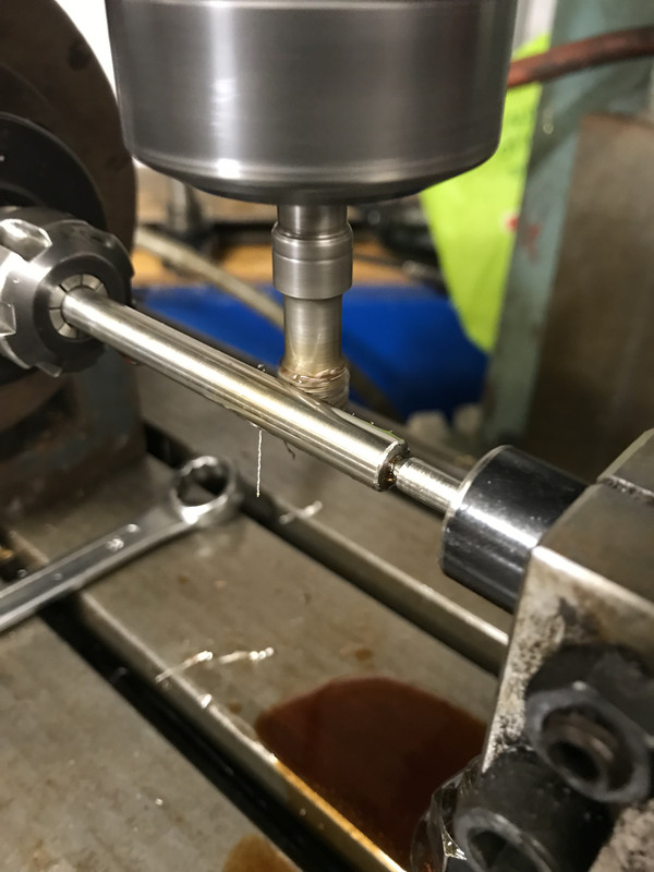
| 451 forum posts 268 photos | Posted by Dave S 27/11/2020 19:10:55 Coming to this a bit late, but is the aim of the project to cut gears, or to make a hobber? Dave
You are correct in thinking about using a rack type cutter in this way , using a rotary cutter,the photo's John
|
| Dave S | 27/11/2020 21:58:30 |
| 433 forum posts 95 photos | I was thinking of the cutter in the spindle, and rotating, more like this Where the cutter traverses in x, and the blank rolls on the a (? Think that's x axis roll) axis synchronised with plunge in the z. Spindle revs are then independent of the cutting of the tooth form. Dave |
| John Rutzen | 28/11/2020 08:05:41 |
| 411 forum posts 22 photos | Hi Dave S, so am I right in thinking that the only thing that detemines the number of teeth is the diameter of the blank? I 've seen and read about those rack form gear cutters before but didn't appreciate that you could roll the blank to generate the gear. |
| Dave S | 28/11/2020 10:33:57 |
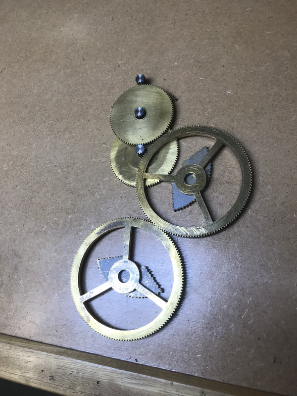
| 433 forum posts 95 photos | Yes. It's much like Hobbing in that respect. All these were cut with the same cutter:
The pinions are profile shifted to avoid tooth undercutting. There is potential to make 'better' than hobbed gears this way too. If you don't roll the blank at all you get roughly 5 facets. With a hob you get a number of facets that is equal to the number of teeth on the hob. With coordinated Z and A you can get equivalent to the step resolution number of facets. Dave |
| Bazyle | 28/11/2020 11:20:35 |
 6956 forum posts 229 photos | Dave, where does the 'roughly 5 facets' come from? Really like this idea |
| John Rutzen | 28/11/2020 12:15:00 |
| 411 forum posts 22 photos | Dave S, surely though you can only roll it so much. Then you would have to step it round to the next tooth. |
| Dave S | 28/11/2020 12:36:23 |
| 433 forum posts 95 photos | The facets come from the adjacent teeth on the cutter shaving the flanks / tops of adjacent teeth on the gear blank. There is a bit of a thread here: Gear cutting with more pictures. Yes the rolling will ultimately lead to the next tooth, but with a (say) 7 tooth cutter the roll can be completed from entry to exit of the “rack” at the target tooth. The adjacent teeth will also get shaved. Once rolled far enough then index to the next tooth and reset the Z to the start and do it again. I planned to gear the roll to my TOS spindle somehow as that’s a fully manual machine, but I haven’t got round to it yet, and if I can get my baby cnc to work reliably the I was going to fix up a rotary axis and do it with cnc - but that’s a way off yet - the CNC nearly works, but so far it hasn’t really cut a complete part due to other distractions. Dave |
| Bazyle | 28/11/2020 13:55:15 |
6956 forum posts 229 photos | thanks, I forgot the cutter as a rack would have more than one tooth. I guess an old horizontal mill, small one as once used in small parts production, would be a good starting point for a dedicated machine. |


Please login to post a reply.
Magazine Locator
Want the latest issue of Model Engineer or Model Engineers' Workshop? Use our magazine locator links to find your nearest stockist!
Sign up to our Newsletter
Sign up to our newsletter and get a free digital issue.
You can unsubscribe at anytime. View our privacy policy at www.mortons.co.uk/privacy
Latest Forum Posts
- hemingway ball turner
04/07/2025 14:40:26 - *Oct 2023: FORUM MIGRATION TIMELINE*
05/10/2023 07:57:11 - Making ER11 collet chuck
05/10/2023 07:56:24 - What did you do today? 2023
05/10/2023 07:25:01 - Orrery
05/10/2023 06:00:41 - Wera hand-tools
05/10/2023 05:47:07 - New member
05/10/2023 04:40:11 - Problems with external pot on at1 vfd
05/10/2023 00:06:32 - Drain plug
04/10/2023 23:36:17 - digi phase converter for 10 machines.....
04/10/2023 23:13:48 - More Latest Posts...
- View All Topics
Support Our Partners


Shopping Partners
Subscription Offer

Latest "For Sale" Ads
- Reeves** - Rebuilt Royal Scot by Martin Evans
by John Broughton
£300.00 - BRITANNIA 5" GAUGE James Perrier
by Jon Seabright 1
£2,500.00 - Drill Grinder - for restoration
by Nigel Graham 2
£0.00 - WARCO WM18 MILLING MACHINE
by Alex Chudley
£1,200.00 - MYFORD SUPER 7 LATHE
by Alex Chudley
£2,000.00 - More "For Sale" Ads...
Latest "Wanted" Ads
- D1-3 backplate
by Michael Horley
Price Not Specified - fixed steady for a Colchester bantam mark1 800
by George Jervis
Price Not Specified - lbsc pansy
by JACK SIDEBOTHAM
Price Not Specified - Pratt Burnerd multifit chuck key.
by Tim Riome
Price Not Specified - BANDSAW BLADE WELDER
by HUGH
Price Not Specified - More "Wanted" Ads...
Get In Touch!
Do you want to contact the Model Engineer and Model Engineers' Workshop team?
You can contact us by phone, mail or email about the magazines including becoming a contributor, submitting reader's letters or making queries about articles. You can also get in touch about this website, advertising or other general issues.
Click THIS LINK for full contact details.
For subscription issues please see THIS LINK.
Digital Back Issues


Donate

 Register
 Log-in
Model Engineer Magazine
- Percival Marshall
- M.E. History
- LittleLEC
- M.E. Clock

ME Workshop
- An Adcock
- & Shipley
- Horizontal
- Mill

Subscribe Now
- Great savings
- Delivered to your door

Pre-order your copy!
- Delivered to your doorstep!
- Free UK delivery!
All Forum Topics > CNC machines, Home builds, Conversions, ELS, automation, software, etc tools > Arduino Gear Hobber