Forum sponsored by:

V-Twin 100cc Design & Build
| Craig Booth 1 | 05/08/2019 21:24:52 |
| 84 forum posts 165 photos | on to another relatively simple item. The prop thrust.
Turned on lathe with counter bore. Reversed in lathe to add 0.5mm lip so only in contact with inner race of bearing.
onto the mill to blind drill for M5 tapping holes
moved onto side to drill thru for M6 grub screw tappings (both sides) which will marry with flats on the crankshaft.
|
| Graham Williams 12 | 05/08/2019 22:51:54 |
| 55 forum posts | Very nice parts Craig..... Graham |
| Emgee | 06/08/2019 09:16:04 |
| 2610 forum posts 312 photos | Hi Craig, what is the purpose of the recess in the front face of the prop driver ? I would have thought you need as much driver to shaft contact as possible with the method of fixing the drive to the shaft, also increased mounting face area for the prop, IMO a key would offer more security in operation and if also on a taper ensure concentricity of the drive system. Emgee |
| Craig Booth 1 | 06/08/2019 21:04:08 |
| 84 forum posts 165 photos | Posted by Emgee on 06/08/2019 09:16:04:
Hi Craig, what is the purpose of the recess in the front face of the prop driver ? I would have thought you need as much driver to shaft contact as possible with the method of fixing the drive to the shaft, also increased mounting face area for the prop, IMO a key would offer more security in operation and if also on a taper ensure concentricity of the drive system. Emgee Hi Emgee, the recess is for the retaining nut which holds the prop driver to the shaft, the grub screws stop the rotation. Your'e right, a key would be the correct method but at the moment that is outside my experience and skill. The key and retaining nut seems to be the way most manufactured RC plane engines of this capacity appear to be fixed. I can image that this may be a part I may need to remake later in the build. Thanks for the comments. |
| Craig Booth 1 | 10/08/2019 21:09:37 |
| 84 forum posts 165 photos | This weekend I worked on the crankcase. Started with a big block of aluminium 76x76x65 in the lathe off centred and bored the main crank axis hole. All the other work was carried out in the mill. The edge chamfers I will do later once the cylinder bodies are located. Now I just have 49 M3 holes to tap
|
| Craig Booth 1 | 14/08/2019 21:16:18 |
| 84 forum posts 165 photos | I didn't get any photos but when I had the stock in the lathe for the cylinders, I also parted off the 2 cylinder heads after cutting the fins. Being the same diameter it was easier to do while the stock was aligned. Then moved to the mill to drill and counter bore the mounting holes (M4 bolts), and the 2 central holes which will be used to fix the rocker bracket. These are M3 threaded, but looking at them now I may increase to M4. All the mounting holes are asymetric due to clearances needed on inlet and oulet holes.
Next I made a basic block to hold the head while the other operations, circlular on one side to match the head, and square on the reverse to hold it in the vice and small rotary table I have.
Fixed in the vice at 15degrees off vertical to drill the 7/32 hole for the sparkplug, tapped at 1/4-32, and counterbored to 12mm for plug wrench clearance.
Moved to vertical in the vice and used 2mm slitting saw to cut fins in the top
Then back to 15 degrees to chamfer the top edge to give plug lead clearance.
|
| Emgee | 14/08/2019 22:17:06 |
| 2610 forum posts 312 photos | Nice looking fins Craig, all look very crisp. Emgee |
| Craig Booth 1 | 17/08/2019 20:39:08 |
| 84 forum posts 165 photos | more work on the head today, but first needed to get the rocker support started as I wanted this in place when I drilled the holes in the cylinder head for the valve sleeves so I would get perfect alignment.
Once valve sleeve holes where drilled, fixed the head to the rotary table to mill the flats for the inlet/exhaust ports and to drill the ports. These ports will need to be re-drilled once the colphos valves sleeves are in place, but the head will need to be anodised first and this cannot be done with any other types of metal present.
|
| JasonB | 17/08/2019 20:44:26 |
 25215 forum posts 3105 photos 1 articles | It's coming along nicely Craig and just goes to show you can hold milling cutters in a drill chuck |
| Craig Booth 1 | 17/08/2019 20:47:27 |
| 84 forum posts 165 photos | Posted by JasonB on 17/08/2019 20:44:26:
It's coming along nicely Craig and just goes to show you can hold milling cutters in a drill chuck Ignorance is bliss. I guess as a newbie I can get away with it.. I presume now that you've hinted that the milling bit should be held in a collet instead for better accurancy? |
| JasonB | 18/08/2019 06:53:34 |
25215 forum posts 3105 photos 1 articles | It is not just accuracy, the main reason is that a drill chuck does not hold the cutter very securely particularly when side load is applied and there is a risk of it moving. If you are lucky it will just ride up and not cut but due to the angle of the helix that the flutes follow the cutter is being pulled down when cutting, it would be a shame if this happened to a part that you had previously put a lot of work into. I think we have all done it to start with or for the odd little cut where it's a faff to change from chuck to collet, (well at least I have) but would be worth investing in a collet chuck such as ER25 or 32 depending on what machine you have. J |
| Craig Booth 1 | 18/08/2019 08:22:11 |
| 84 forum posts 165 photos | Posted by JasonB on 18/08/2019 06:53:34:
It is not just accuracy, the main reason is that a drill chuck does not hold the cutter very securely particularly when side load is applied and there is a risk of it moving. If you are lucky it will just ride up and not cut but due to the angle of the helix that the flutes follow the cutter is being pulled down when cutting, it would be a shame if this happened to a part that you had previously put a lot of work into. I think we have all done it to start with or for the odd little cut where it's a faff to change from chuck to collet, (well at least I have) but would be worth investing in a collet chuck such as ER25 or 32 depending on what machine you have. J Thanks for the info Jason, that's something new i've learnt. I do have a collet set that i use for the larger (16mm bit), but will look to use them for the smaller also. |
| Mark Gould 1 | 12/09/2019 09:39:07 |
| 231 forum posts 131 photos | Craig, Loving this build thread immensely. As an alternative to holding your milling cutters in a collet you can also buy end mill holders from Arc which have fixed sizes. I have 2 ready to go with cutters in them 6mm and 10mm, being 2 sizes I use often. Mark |
| Lainchy | 12/09/2019 09:54:11 |
 273 forum posts 103 photos | Just spotted this thread, and it's superb! Nice work! I'm a noob myself (Far MORE of a noob than you! Far far behind lol) I did try a milling cutter in my B16 chuck, and found that it pushed it off the B16 taper (maybe I just hadn't pushed it home enough) Cracking work though! |
| Craig Booth 1 | 30/11/2019 20:02:01 |
| 84 forum posts 165 photos | Hi all, well its been a few months and I been concentrating on the plane rather than the engine, but now that winters here starting to get back into it. Finished off one of the rocker supports.
and then started on the front crankcase housing.
lump of aluminium turned and bored to shape. Main bearing will be a press fit, front bearing a push fit.
on the vertical rotary table on the mill I cut clearance for the valve sleeve and octagonal face plate.
and drilled and tapped holes for the magnet sensor
drilled the holes for fixing
|
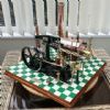
| Craig Booth 1 | 30/11/2019 20:04:46 |
| 84 forum posts 165 photos | and I couldn't resist putting it together and seeing what it looked like on the plane
|
| Craig Booth 1 | 29/03/2020 19:31:40 |
| 84 forum posts 165 photos | Today I anodized the cylinder head and made the valves sleeves from Colphos. Pretty happy with the results.
|
| Henry Brown | 29/03/2020 21:15:19 |
 618 forum posts 122 photos | Great job Craig, that will be some plane! Not spotted this before but will follow the future updates with interest... |
| Craig Booth 1 | 09/04/2020 08:44:32 |
| 84 forum posts 165 photos | The last couple of days has been work on the tappet guides and sleeves. I had to redesign these as I made an error in making the space available for the cam lobes to small a diameter. This has meant that I have needed to make the tappets much larger diameter 8mm diameter to meet the minimum calculated in the "cam with draw" spreadsheet I have been using. The main guides from aluminium H30 and the sleeves Colphos. Guides then anodised.
|
| Craig Booth 1 | 09/04/2020 08:46:07 |
| 84 forum posts 165 photos | also made start on the first conrod (alu H15), with a needle bearing on big end. Small end will have a colphos bushing.
|


Please login to post a reply.
Magazine Locator
Want the latest issue of Model Engineer or Model Engineers' Workshop? Use our magazine locator links to find your nearest stockist!
Sign up to our Newsletter
Sign up to our newsletter and get a free digital issue.
You can unsubscribe at anytime. View our privacy policy at www.mortons.co.uk/privacy
Latest Forum Posts
- hemingway ball turner
04/07/2025 14:40:26 - *Oct 2023: FORUM MIGRATION TIMELINE*
05/10/2023 07:57:11 - Making ER11 collet chuck
05/10/2023 07:56:24 - What did you do today? 2023
05/10/2023 07:25:01 - Orrery
05/10/2023 06:00:41 - Wera hand-tools
05/10/2023 05:47:07 - New member
05/10/2023 04:40:11 - Problems with external pot on at1 vfd
05/10/2023 00:06:32 - Drain plug
04/10/2023 23:36:17 - digi phase converter for 10 machines.....
04/10/2023 23:13:48 - More Latest Posts...
- View All Topics
Support Our Partners


Shopping Partners
Subscription Offer

Latest "For Sale" Ads
- Reeves** - Rebuilt Royal Scot by Martin Evans
by John Broughton
£300.00 - BRITANNIA 5" GAUGE James Perrier
by Jon Seabright 1
£2,500.00 - Drill Grinder - for restoration
by Nigel Graham 2
£0.00 - WARCO WM18 MILLING MACHINE
by Alex Chudley
£1,200.00 - MYFORD SUPER 7 LATHE
by Alex Chudley
£2,000.00 - More "For Sale" Ads...
Latest "Wanted" Ads
- D1-3 backplate
by Michael Horley
Price Not Specified - fixed steady for a Colchester bantam mark1 800
by George Jervis
Price Not Specified - lbsc pansy
by JACK SIDEBOTHAM
Price Not Specified - Pratt Burnerd multifit chuck key.
by Tim Riome
Price Not Specified - BANDSAW BLADE WELDER
by HUGH
Price Not Specified - More "Wanted" Ads...
Get In Touch!
Do you want to contact the Model Engineer and Model Engineers' Workshop team?
You can contact us by phone, mail or email about the magazines including becoming a contributor, submitting reader's letters or making queries about articles. You can also get in touch about this website, advertising or other general issues.
Click THIS LINK for full contact details.
For subscription issues please see THIS LINK.
Digital Back Issues


Donate

 Register
 Log-in
Model Engineer Magazine
- Percival Marshall
- M.E. History
- LittleLEC
- M.E. Clock

ME Workshop
- An Adcock
- & Shipley
- Horizontal
- Mill

Subscribe Now
- Great savings
- Delivered to your door

Pre-order your copy!
- Delivered to your doorstep!
- Free UK delivery!
All Forum Topics > Work In Progress and completed items > V-Twin 100cc Design & Build