Forum sponsored by:

Muncaster's Simple Entablature Engine
| geoff walker 1 | 03/09/2019 10:47:24 |
| 521 forum posts 217 photos | Hi Jason and All, I've had my eye on this engine for for quite some time so when I heard you had a series of articles in M.E. magazine I was naturally interested to see what building and machining methods you would use. As far as the size was concerned I always favoured making the engine close to the original dimensions in Muncasters book. As you will know this was a 3/4" stroke and bore engine and is around 3/4 of the size of your 24mm bore design. I just prefer the smaller scale, something you can place on the palm of your hand. The photo below is of the completed framework. I will be making the top end parts next, bearing pedestals, bearings crankshaft, crank etc., all to your building design but more or less 3/4 of all the sizes. I shall retain the original throw 9.5mm and probably the original bore 19mm (3/4" I have to say I was very sceptical of your "flexed" taper turning method, did you get that from a textbook? Not a problem, works fine but I left the spigot off the top and drilled and tapped for a 4 BA screw. The base is laminated from M.S. as you suggested the parts being rivetted together with 1/8" csk. head rivets, just like we used in school metalwork lessons all those years ago. Photo in the next post, not uploaded yet. Geoff
|
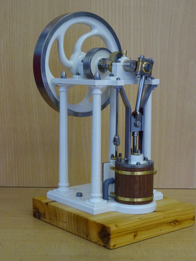
| geoff walker 1 | 03/09/2019 10:49:52 |
| 521 forum posts 217 photos | My muncaster frame 3/4 size geoff |
| JasonB | 03/09/2019 17:29:55 |
 25215 forum posts 3105 photos 1 articles | Looking good Geoff, should not be too hard to scale my sizes back down as 1mm will equal 1/32" an dI tried to keep to whole units in most cases. You will have to plug the hole under the cylinder as I did not include a cylinder bottom, alternative would be to add a thin cover and reduce the conrod and guide bar length to suit. |
| geoff walker 1 | 16/09/2019 15:22:56 |
| 521 forum posts 217 photos | Hi Jason, Just reading the latest M.E. I notice that you have again used the boring head in a very creative manner. This time to shape the exterior of the stuffing box bosses on the valve chest. clever stuff, I really must get a boring head for my sx2, looks to be a really useful piece of kit. I wiil be interested to see how you made the cross head guides and then aligned them accurately. I have a idea how to do it but will wait and see how you have it done before I order some stock. Enjoying the articles J, thank you Geoff |
| JasonB | 16/09/2019 18:20:44 |
25215 forum posts 3105 photos 1 articles | Got to know you ar eenjoying the build and learning a few new methods along the way. Hopefully the text will explain my methods with the guides and highlight where the critical items are, if not just ask away. I did not post any extra photos to go with the last part as most were used in the mag but this one shows the finished chest and cover in place (temporary screws)
|
| JasonB | 21/09/2019 20:13:46 |
25215 forum posts 3105 photos 1 articles | Additional content to go with part 5 Initial turning and threading of the cross head before transferring to the mill
Another shot of the crosshead being reamed for the pin
Asembled crosshead, conrod and big end bearings
|
| robert eggleston | 30/09/2019 22:20:35 |
| 28 forum posts 9 photos | There are very nice Cast Iron spiral spoked flywheels available on this side of the pond from Martin Model and Pattern in the appropriate size. |
| Rockingdodge | 01/10/2019 11:40:59 |
 396 forum posts 111 photos | Assuming this side of the pond meaning the US of A! |
| JasonB | 01/10/2019 13:14:29 |
25215 forum posts 3105 photos 1 articles | Thank's Robert I had seen those before as they are also sold by Little Machine Shop as well as M&M Though the rim is a bit heavier. Out of interest I did also run the CAM and generate the code to cut the spokes into a pre turned blank and it looks good on the screen. |
| Rockingdodge | 01/10/2019 15:48:45 |
396 forum posts 111 photos | What would be the options for a spiral flywheel in the UK Jason? |
| geoff walker 1 | 01/10/2019 16:04:37 |
| 521 forum posts 217 photos | What would be the options for a spiral flywheel in the UK Jason Good luck with that rocking I can't find one at the usual suppliers. I thought Reeves had one but can't see it on their website Geoff |
| JasonB | 01/10/2019 18:33:48 |
25215 forum posts 3105 photos 1 articles | Posted by Rockingdodge on 01/10/2019 15:48:45:
What would be the options for a spiral flywheel in the UK Jason? Same place as when you asked last time on the first page I messaged Lee and he says he has no flywheels listed at the moment as out of the country until the middle of the month. he will cast some more when he gets back. I will keep you all informed. Please not I have no links with lee, just a satisfied customer. he used to do the casting for College Engineering before they changed hands as it was one of the flywheels they sold. |
| Rockingdodge | 01/10/2019 19:00:17 |
396 forum posts 111 photos | Yes Jason, I did remember but assumed that Lee wasn't going to make them any more and was clearing surplus stock. My mistake, your fault. |
| paul rayner | 01/10/2019 19:15:40 |
| 187 forum posts 46 photos | Iv'e never cut a cylinder from bar stock before, but seemingly "the process may look a bit daunting" but "the process is quite simple" he goes-
cut a hole
oh dear! port face won't be big enough start again
better
port face big enough
Ok it's not perfect port face is 0.2mm too wide and if you look close iv'e nicked the inside of the bottom flange, but that will be covered any how. so on the whole to say I've never done this before i'm quite pleased with the results, I'm going to leave the holes for the steam chest till later when I decide weather to make the chest 0.2mm wider or not. the exhaust is drilled but not tapped yet, a bit of fettling, honing and jobs a good un. cheers Jason |
| JasonB | 01/10/2019 19:25:15 |
25215 forum posts 3105 photos 1 articles | You are off to a good start, I doubt the 0.2mm will make a lot of difference so upto you if you make the chest and cover wider or to drawing.
I have just had a message from Lee to say that he can cast in most materials to your own supplied patterns. I've only had CI from him which was cleanly cast and a nice bit of iron to machine. Anyone with deep pockets and a liking for a bit of bling could ask for a bronze flywheel. he can be contacted by message on e-bay here |
| geoff walker 1 | 04/10/2019 19:35:54 |
| 521 forum posts 217 photos | Hi Paul, nice work on the cylinder as Jason said that's a good start. I'm following Jason's building methods but scaling his sizes down to approximately 3/4 full size. As I didn't have a suitable piece of cast iron in stock for the cylinder so I decided to treat myself to a 10v cylinder which is just about the right size at 19mm stroke and bore. Got that machined up and have made the valve chest to Jason.s design. Also made some progress on the bearing blocks which were tricky to make as they are quite small.
Still looking for a 3" flywheel and may use the 10v one which I have had for some time. Jason I took note of your comments in the latest M.E. regarding the use of B.M.S. for the crosshead guides. It was a good point I assume the the cold roll steel is less stressed and thus not as liable to distort. Once again some good machining ideas in the latest issue in particular the way you made the crankshaft. Geoff |
| JasonB | 04/10/2019 20:00:52 |
25215 forum posts 3105 photos 1 articles | Some mor egood progress there Geoff and good use of the casting, I would think that anyone building to my size may be able to make use of a Stuart No7 cylinder as there should be enough metal there for the slightly smaller bore or make it 25mm instead of 24mm.You don't want to believe everything you read in magazines that should have been HOT rolled Another option for those wanting curved spoke flywheels is to fabricate, Find's site has a good guide |
| JasonB | 04/10/2019 20:07:34 |
25215 forum posts 3105 photos 1 articles | Extra photos to go with part 6 Milling the recess in the valve
Held the other way up the slots for rod and nut can be added. If a vice stop is positioned before the part is removed from the vice after machining the recess you can put it back in and keep the X axis datum, Y still stays the same as fixed jaw will still locate the work in that axis.
Marked out eccentric material to give a guide of where to machine to
Completed eccentric strap, eccentric and rod. Note position of grub screw at the highest point of the eccentric which will help with setting the timing in the final part 7.
|
| john Chappell 1 | 11/10/2019 05:51:43 |
| 14 forum posts 3 photos | Hi Jason, In ME 4621 pp 457 Why are crosshead guides not symmetrical? ( mirror image ) Diamension 55.3 + 23.5 does not add up to 79.5 mm.
REGARDS, John Chappell |
| JasonB | 11/10/2019 07:04:26 |
25215 forum posts 3105 photos 1 articles | Welcome to the forum John, Are you having a go at making this one?
The two dimensions don't add up as one is to the internal corner and the other to the external as these are the extents of the two cuts I dimensioned it that way to give builders the sizes to cut. Will post a better detail later but this is the blown up drawing
|
 .
.


Please login to post a reply.
Magazine Locator
Want the latest issue of Model Engineer or Model Engineers' Workshop? Use our magazine locator links to find your nearest stockist!
Sign up to our Newsletter
Sign up to our newsletter and get a free digital issue.
You can unsubscribe at anytime. View our privacy policy at www.mortons.co.uk/privacy
Latest Forum Posts
- hemingway ball turner
04/07/2025 14:40:26 - *Oct 2023: FORUM MIGRATION TIMELINE*
05/10/2023 07:57:11 - Making ER11 collet chuck
05/10/2023 07:56:24 - What did you do today? 2023
05/10/2023 07:25:01 - Orrery
05/10/2023 06:00:41 - Wera hand-tools
05/10/2023 05:47:07 - New member
05/10/2023 04:40:11 - Problems with external pot on at1 vfd
05/10/2023 00:06:32 - Drain plug
04/10/2023 23:36:17 - digi phase converter for 10 machines.....
04/10/2023 23:13:48 - More Latest Posts...
- View All Topics
Support Our Partners


Shopping Partners
Subscription Offer

Latest "For Sale" Ads
- Reeves** - Rebuilt Royal Scot by Martin Evans
by John Broughton
£300.00 - BRITANNIA 5" GAUGE James Perrier
by Jon Seabright 1
£2,500.00 - Drill Grinder - for restoration
by Nigel Graham 2
£0.00 - WARCO WM18 MILLING MACHINE
by Alex Chudley
£1,200.00 - MYFORD SUPER 7 LATHE
by Alex Chudley
£2,000.00 - More "For Sale" Ads...
Latest "Wanted" Ads
- D1-3 backplate
by Michael Horley
Price Not Specified - fixed steady for a Colchester bantam mark1 800
by George Jervis
Price Not Specified - lbsc pansy
by JACK SIDEBOTHAM
Price Not Specified - Pratt Burnerd multifit chuck key.
by Tim Riome
Price Not Specified - BANDSAW BLADE WELDER
by HUGH
Price Not Specified - More "Wanted" Ads...
Get In Touch!
Do you want to contact the Model Engineer and Model Engineers' Workshop team?
You can contact us by phone, mail or email about the magazines including becoming a contributor, submitting reader's letters or making queries about articles. You can also get in touch about this website, advertising or other general issues.
Click THIS LINK for full contact details.
For subscription issues please see THIS LINK.
Digital Back Issues


Donate

 Register
 Log-in
Model Engineer Magazine
- Percival Marshall
- M.E. History
- LittleLEC
- M.E. Clock

ME Workshop
- An Adcock
- & Shipley
- Horizontal
- Mill

Subscribe Now
- Great savings
- Delivered to your door

Pre-order your copy!
- Delivered to your doorstep!
- Free UK delivery!
All Forum Topics > Stationary engines > Muncaster's Simple Entablature Engine