Forum sponsored by:

Steam Engine Number One
A Build Log (hopefully)
| Iain Downs | 08/12/2018 20:54:44 |
| 976 forum posts 805 photos | Crank Balance One of the things I've been working on is how to get the crank balance - by science rather than trial and error. I started trying to use maths - without the aid of my Mathemetician son who demanded payment! I had quite a few goes at this - with online resources doing the calculation, but despite having put quite some time into it, it soon became obvious that solving complex integration is something I'm going to have to look back on and not forward to. My next though followed the hammer and nail principle (if the only tool you have is a hammer) and, as software chap, I thought I'd write a program which would calculate the balance numerically rather than analytically. Fortunately, before I dove into this task (fun though it may have been), it occurred to me that this was an everyday task for proper engineers and perhaps OnShape had something built in! It does and with a bit of trial and error it would seem that the crank as designed is nearly in balance and just needs some 8x6 mm cylinders attaching!
Iain |
| JasonB | 08/12/2018 21:00:26 |
 25215 forum posts 3105 photos 1 articles | The crank itself may be in balance but once you have the mass of a conrod and piston attached that is going up and down all hell breaks loose. The balance weight is generally more than is needed to balance just the pin. |
| Iain Downs | 09/12/2018 07:54:58 |
| 976 forum posts 805 photos | Ah. So wrong again! But learning So what does one do? Is it trial and error? Can I start by balancing the mass of the big end bearing? Should I just put a threaded hole through for now so I can experiment? Iain |
| JasonB | 09/12/2018 08:12:24 |
25215 forum posts 3105 photos 1 articles | There are methods for doing it but not something I have really gone into. I seem to recall that the conrod complere with big end bearing is held horizontally with the big end resting on scales and the small end otherwise supported so you can get the weight. Though the piston must come into it somewhere. You then add this weight around the pin and calculate the weight needed to bring this into balance. May be best to ask in a new thread which may attract more attention of those that know about these things. Definately add the threads for the weights as then you can always play about later. |
| Iain Downs | 09/12/2018 20:28:28 |
| 976 forum posts 805 photos |
Today, I trimmed the non pin end of the journal to be a bit nicer, split the journals apart with some heat and cleaned them up a bit.
Next step is to glue the pin end. My plan (subject the sage advice of my elders and betters), is to
I'm thinking that I want to leave the main shaft out until I've done the main bearings and I can use it with a bit of grinding diamond paste to lap them in. The glue the main shaft in, cut the middle out and finish. Originally, I'd got another 20mm bar to act as a lap, but I'm loathe to buy yet more silver steel (main shaft now 22mm).
Iain
|
| Neil Wyatt | 10/12/2018 11:25:29 |
 19226 forum posts 749 photos 86 articles | A rule of thumb for a single cylinder is balance the rotating weight then add 50% of the reciprocating weight. Will have some tearing their hair out, but for an engine of the size you are building it should be fine. Neil |
| Iain Downs | 12/12/2018 18:48:45 |
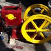
| 976 forum posts 805 photos | So after a few digressions, a bit more work on the engine. All that was left (for now) to do with the crank was to slap some loctite in and glue in the pin. I used a couple of bits of scrap to make sure that the pin shaft came to exactly the end of the journals. I was in a bit of a panic for this thinking I only had seconds to get it right, but I now gather setting (curing) time is more flexible. As you can see I assembled it on a (protected!) surface table with the main shaft in place too (not glued yet) to make sure every thing lined up.
Next was to assemble the crank case. The original plan (well the last original plan) was to sliver solder it, but experiences elsewhere put me off that as an idea - there's far too much metal. I originally originally intended to just bolt it together, but felt that this was too inaccurate. Instead, I decided to pin it in 4 places and secure with a pair of bolts at each end. First task was to drill the pin / pilot holes. These at 2.8mm with a view to reaming to 3mm and using some silver steel I'd bought at a show 'because it might come in handy'. It has (OK, 18 months later, but..).
I thought about entitling this one, 'you can never have enough clamps'. In fact this task took my little CMD10 right to it's limits.
If the crank case had been 5mm longer I would have been very hard pressed to do the drilling. Well done! you might say for such careful design work. Hmmmm. (blush - absolute luck!). Next to ream out to 3mm. It turned out that I had only got 3mm in machine reamers and I actually don't trust any of my kit to be accurate enough to hold a machine reaminer and not overbore, so I got a 3mm hand reamer. Next to pin, bolt and hammer in the pins.
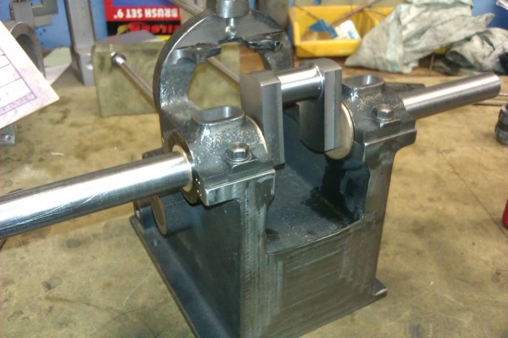
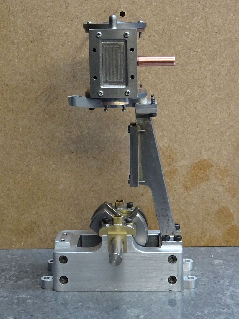
And finally, here is the crank on the crankcase. Cosmetically - I still need to make the main bearings.
Next step is to try and make the main bearings. A bit daunting. I have a 50x50x65 lump of cast iron out of which these must appear. I'm planning in squaring it up in the lathe (partly because the mill will take forever and partly to extend the range of my fumbles). I'd like to cut it into 4 (two bearings in half) with a slitting saw, but I've had bad experiences with that. I suspect the mill is out of tram so that my be the first job tomorrow. And before I fir it, I'm planning on facing the top of the crankcase to provide a good registration surface.
Iain |
| Iain Downs | 13/12/2018 16:51:38 |
| 976 forum posts 805 photos | Another setback It seems that the lump of cast iron I had lying around which I was going to make the bearings from isn't. Isn't cast iron that is. My filing seemed to make dust, but when I was playing with truing it up on the lathe (a venture with decidedly mixed results), I got curls not dust. I moved it to the mill and trimmed a bit of it off and then the same with some known cast iron. the cast is producing dust, the unknown metal curls. More expense (but thank God for ebay).... ON the other hand, I had a look at the tramming of the micro mill and it's better than expected. With a bit of bolt tightening on the column I've got it .05 mm out front to back and .03 or so left to right. I appreciate that this may seem like the the most appalling laxity to the experts among you, but I've tried to set this machine up before and if you remove the column to shim, the whole setup changes. Quit whilst you are ahead (or at least not too far behind). Tomorrow is my last day of leave and it's a domestic day followed by the works do, so my focus is going to be off this now until Christmas week. I might just have a go at starting the cylinder tonight, though. Or I might do some of the domestic jobs I've promised. Hmm, fun? or Brownie Points...
Iain |
| JasonB | 13/12/2018 17:02:26 |
25215 forum posts 3105 photos 1 articles | Ian, you could make your bearing blocks from aluminium which will be easy to machine ans just slip in some bronze bearings, I did similar the other week when the cast items were consigned to the bin due to poor quality. having said that with the right tools and a nice bit of iron you can get pleasing swarf not just dust
Looking at the size of that fabricated base you would still be here until next Xmas trying to heat that lot up with what you had, I think even the standard Sievert burner may be a bit small for lumps like that. |
| Iain Downs | 13/12/2018 17:39:17 |
| 976 forum posts 805 photos | Hmm. So would this be a sleeve (like f:0">this one on eBay) I would get one with a 22mm inner bore and just slip it in the bearing blocks? Or do I split it somehow? Do I need to lap it in? How would I retain it? would I need to machine a grove? Do I need to put an oil groove inside it? Aluminium is appealing. So much easier to work with. And a million other questions. I presume I would still need to make a split bearing for the big end and eccentric... Iain |
| JasonB | 13/12/2018 19:02:22 |
25215 forum posts 3105 photos 1 articles | I have used the Oilite type bearings on a couple of hit & miss engines where their use is specified and it works out as a quick and easy way to do it. They are really designed to be pressed into a hole which compresses the bush slightly so are a fraction oversize as supplied but only a thou or so, Can't see why you could not split them although the resulting gap left by the saw cut may break down the oil film. If you do go down that route then you can get them with a flange on one side, if this were placed on the inside edge the crankshaft webs can butt upto the flange and that will stop the bush moving sideways, a bit like this
The other option is to solder two blocks of bronze together then machine them to fit your shaft and reduce the middle section so you have a flange at each end, could even glue some CI together as it's a bit cheaper than bronze. Something along these lines would work for you.
If you don't fancy round then square/rectangular work too
Yes you will need to split the big end to get it onto the crank, depending on eccentric design you can get away without splitting the strap but on the size of engine you are making I would split it. |
| Mikelkie | 13/12/2018 19:39:37 |
 135 forum posts 13 photos | I cast aluminium plummer block type of bearing supports for a cropping machine i built about 2 years ago with a shaft od of 30 mm. the aluminium was automotive cylinder heads from scrap dealers. the final reamed holes left a shiny finish and is a exellent bearing material. I will try and use alli casting wherever possible,and currently making horn blocks for a 7 1/4 loco from aluminium too |
| Iain Downs | 18/12/2018 07:23:11 |
| 976 forum posts 805 photos | I got my real cast iron block yesterday and spent an hour cutting and squaring
I do like my Aldi cut-off saw! A precision instrument it is not, but it gets through big lumps of metal in no time. I'm working out how to use it to saw a bit of a 100mm cast iron round bar, which will need different clamping somehow.
The plan is to square up and, from a face end cut it 20mm up, then glue back together then cut 22mm out and re=glue. Finally trim the rest to size so I have two bearings hidden in the iron and bore out and finish. May finish squaring and do some cutting tonight if all goes well.
Iain |
| Iain Downs | 27/12/2018 16:01:44 |
| 976 forum posts 805 photos | So 10 days on and a mix of results to report. As stated the plan was to slit the iron into 4, bore and break apart. Here's how far I've got. I wanted the horizontal split to be exactly 20mm above my base. I set up the slitting saw using some precision 2 4 8 blocks as below
Of course the slitting saw would only get half way through so I needed to turn the iron round and saw from both sides
Nearly done....
and here is the result.
The astute among you will spot that the saw cut wasn't perfect. In fact there was a definite angle on each side leading to two facing ridges, each at half the width. I thought I could lap them out with some wet and dry on the surface plate, but this was just not working (given that the effective shape was convex this should not have surprised me. I ended up scraping to the point where it no longer visibly rocked. The next cut, I planned to mill flat afterwards and measured accordingly. Now for the boring part (so to speak)
then boring with a home ground hss bar. I think for the cylinder I will need to make a more substantial boring bar - there's too much flex in this.
In the end though it's not too bad. It might be a thou or two over but I think it will be alright.
Initially, I thought I'd screwed things up with the bore not being straight with respect to the base and sides. Having remeasured, I'm seeing a drop of about 2 thou from to back, but that's comparable to the taper on the bore. The bore isn't quite centred but I make sure to drill and mount with the shaft in place so it will be reasonably OK. phew! I dd NOT want to start this bit again.
Iain |
| Iain Downs | 29/12/2018 18:09:43 |
| 976 forum posts 805 photos | Another couple of days of progress. Firstly, I wanted to skim the crankase top and bottom to get some registration surfaces. MInd you with my little mill (CMD10) there's a limit to how nice I can get it - my attempts in the past to use a fly cutter were fairly abortive though I should give it another go now I'm a little less clueless.
This is the top of the crankcase. I did the underside with a 4 flute 10mm HSS bit and this with a 3 flute 10mm carbide bit. The carbide works so much better even on a final skim of a few thou. What's interesting is that you can just about see the 'crop circles' getting steadily worst towards the top left. the bottom right has the gibs fully engaged and the top left only just hanging on - the effects on rigidity are clear. Next up was to drill the bearings through
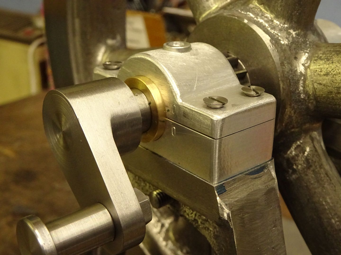
I'd left 3.3 mm pilot holes in the bottom of the bearings and the idea of this assembly was to drill through to the crankcase with the shaft as near central as possible and able to move freely. Sadly, I discovered at this point that I'd mucked something up and the circular buffer bits (I have no idea what you call them) stick out a bit too far so that the journals won't fit. That's not a crisis - once I've mounted the bottom bearings permanently I'll just skim off a bit with my mill. Here's is the work in progress with the bearings temporarily bolted to the crankcase.
As this stands the shaft is a little stiff but only slightly. It may ease up with some better bolts (the only ones I had have an angle on the head end which forces them into the centre of the hole, some cap heads or simliar may allow ab bit of movement. Of course I don't have any of the right length so will have to order some. Once that's done the next task is to lap the shaft in place. I'm going to use this shaft (which will eventually be the real one (using parts of it which won't actually be in the bearings. The bearings are over sized by between 2 and 3 thou. Should I try and reduce this by slimming down the bearings and lapping or is that sort of OK? Also, I need to put some kind of lubrication channel in I think. I was going to drill a 2mm hole through the top bearing. Should I turn a grove on the inside or will the oil get there just fine! May be a bit of a break on this now - leave is almost over and I've a skiing trip coming up. Next major item is the cylinder which will be er, interesting.
Iain
|
| JasonB | 29/12/2018 19:46:15 |
25215 forum posts 3105 photos 1 articles | With 2-3 thou clearance the shaft should turn quite freely, rather than lap it in blue the shaft and see where it is contacting the bearings and then decide on whats needed.
Oil hole should be fine on it's own |
| Iain Downs | 01/01/2019 17:55:46 |
| 976 forum posts 805 photos | The 30th and 31st were eventful on the Steam Engine front. The first thing I attempted was to bring down the top of the bearing cap. To do this I thought I'd give the 17mm indexed face mill I bought a few years back and abandoned after it kept smashing the mill gears. Yes, I know it was the driver's fault not the tool! Since then I have fettled the mill somewhat (and perhaps gained a little in experience), with the main improvement being an adjustment to mesh the gears better, after which (2 years ago) the gears stopped breaking. Maybe it wasn't entirely me after all... The face mill worked really well. With some care I could take off 1.5mm in one pass, though it was too easy at that depth to overload the little motor and stall it. The thing I did wrong was to clamp it badly in my vice and it shifted. Which gouged the piece and stalled it. Also it turned out broke a cog off the motor gear. The mill still ran, and I finished off the bearing caps. I have a box of spare gears for the CMD10, bought when breaking them was a weekly occurrence. Yes, you guessed. All the gears needed - apart from the motor gear. I downed tools for the day and settled in front of the PC to call up Ketan's site. Then I thought, 'I have a 3D printer'. A few moments with Onshape and I have a gear which looked like it was about right - it wasn't but it only took 20 mins or so to print. Armed with experience I printed a mod 1.5 16 tooth 8mm thick gear with a 3mm keyway.
After a bit of fettling (an 8mm reamer and a broach I'd made earlier) to tune up the bore, I fitted it and it worked! First use was to counterbore the bearing bolt hole (now the bolts have arrived. Not too stressful and it worked a charm.
Next was scraping the bearings. This seemed to go better than my attempts at scraping flat. I think that one of the bearings is a little large and I have trimmed the faces of the bearing caps to tighten up a little. For one reason or another the bores are not quite in line with the base of the cap so I was scraping out at an angle. The shaft blued.
Not the best of photos, but it's hard enough to see with mark 1 eyeball. This isn't the final scrape by the way. I expect I could do better - the bearing surface on one side is quite good (lots of small high spots) - on the other side less so. In place I've got a horizontal rattle of 0.01mm or so which I think is reasonable. No doubt they will bed down. Next was to use a 10mm carbide end mill to widen the gap so the journals would actually fit (and the new bearing coped well with this at 2000 RPM). Then it was 'call it a day'. I still need to glue the shaft, pin it and cut out the middle. However, I like to quite whilst I'm ahead - had I buggered something up it would have spoilt a decent couple of days of work!
I could of course, have completed this today, but I felt weary and a little unwell for no reason I can quite put my finger on. My wife claims it was the copious amounts of red wine in celebration of the year and (and, as it happens, my birthday), but that hardly seems likely to me... With best wishes to you all for 2019
Iain
|
| Iain Downs | 04/02/2019 21:02:41 |
| 976 forum posts 805 photos | So it's month since my last post. My time has largely been taken up with work (ugh), a weeks skiing in France (cold) and a week with customers in Toronto (very cold). I've also quit my job so will be a happily free man in a few weeks - though hopefully not for too long. If anyone wants a brilliant software designer/architect/manager type person then drop me an IM! (am I allowed to advertise, Neil?) But back to the real world. I've got round to gluing the main shaft of the crankcase into the journals, but not yet drilled, reamed and bashed for pins, cut through the shaft and tidy up. This weekend probably. Instead I've started work on the cylinder. The first thing was to make a boring bar to take an HSS bit. I've an indexed boring bar with a carbide bit, but experience has shown that it won't cut dead parallel when finishing off a cylinder. This gave me a good excuse for buying a square Stevenson's block with an ER32 collet holder. I have some 13mm rod which I cut and faced, set in the collet holder, stood on a couple of parallels and pushed against a bit of 10x20mm bar aligned with the table and against a set bolt to register it (you can't see that in any of the photos)
This is me squaring the end to fit in the tool holder. It's a terrible photo really! Next find the edge with a wobbler. Which disintegrated in the process (the rod came out of the ball), but some locktite fixed that. Centre drill to spot the hole for some 6mm hss bar, drill to about 4 mm then to 5.8.
you can see how the block is held and registered a bit better in this photo. Turn the block through 90 degrees, centre drill and the drill through with a 4..4 mm for the M5 grub screw.
Finally, ream the bit hole to 6mm and tap the grub screw hole
And here's the finished product!
I don't think I've got a good profile on the bit, but that's easy enough to regrind.. The other thing I've started on is the cylinder. Somehow a complex work of art must emerge from the dull envelope... I started off by finding the best end (one end was quite flat and square, the other not so much) and squared the other end up in the mill. I don't really know why I did it this way as it would have been quicker and easier in the lathe.
And then marked up to make sure that the cylinder actually fits in the er, cylinder and to find the centre for boring
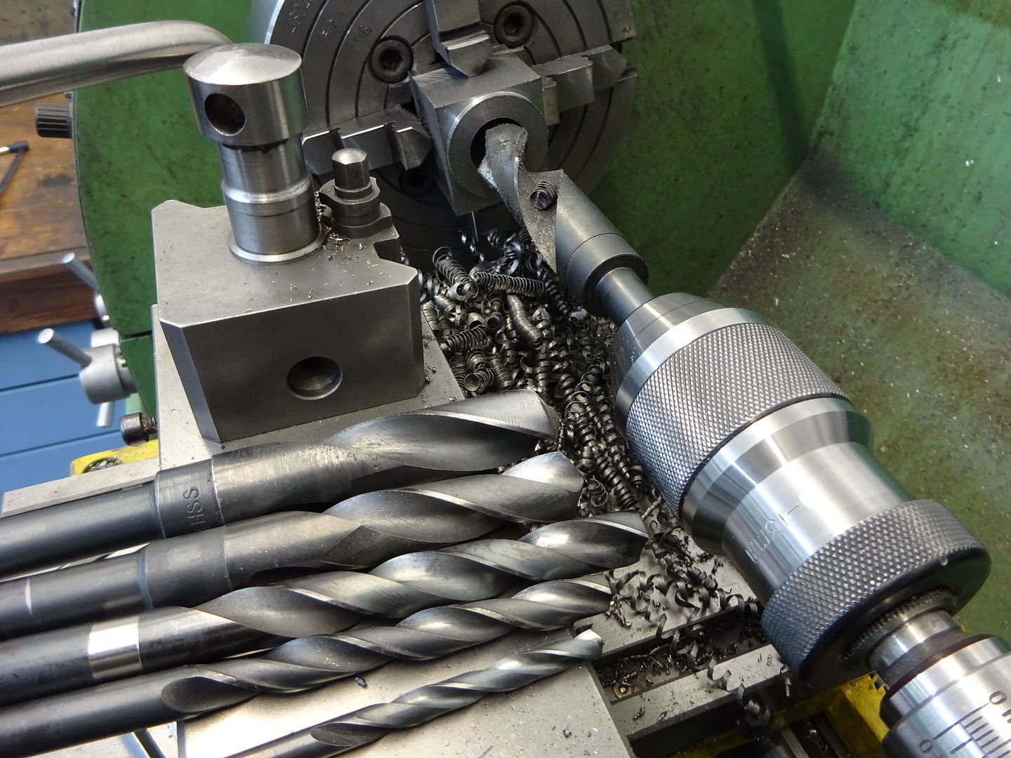
Is this how Michelangelo felt when he first dragged his charcoal across the marble that would be David? I've also invested in some long drills. It's all very well having a stiff boring bar, but you still need a hole to bore out from! I've got a bunch of them from 2mm up to 10mm - does anyone have advice on the best size to start from? The chances of a 2mm drill getting through 85mm of cast iron seem remote, but I don't know how easily a big drill will go through. Or am I approaching this the wrong way and should start with some other sort of drill? Iain |
| Dennis R | 04/02/2019 22:17:14 |
| 76 forum posts 16 photos | Iain Dennis |
| JasonB | 05/02/2019 07:09:08 |
25215 forum posts 3105 photos 1 articles | Start with a 6mm standard length jobber and go in about 40mm. then a 10mm and go in 30mm, you can then go back to the 6mm drill and cut a further 25mm. Now another 25mm with teh 10 and then start part way with say 12mm. Then if you have any blacksmith drills open up further with those. The basic idea is that you don't go in areally long way with the drill so less chance of binding and you don't need to back the drill out as far to clear swarf. As said collet should snap into the nut which will then pull it out of the taper when undone see this
|


Please login to post a reply.
Magazine Locator
Want the latest issue of Model Engineer or Model Engineers' Workshop? Use our magazine locator links to find your nearest stockist!
Sign up to our Newsletter
Sign up to our newsletter and get a free digital issue.
You can unsubscribe at anytime. View our privacy policy at www.mortons.co.uk/privacy
Latest Forum Posts
- hemingway ball turner
04/07/2025 14:40:26 - *Oct 2023: FORUM MIGRATION TIMELINE*
05/10/2023 07:57:11 - Making ER11 collet chuck
05/10/2023 07:56:24 - What did you do today? 2023
05/10/2023 07:25:01 - Orrery
05/10/2023 06:00:41 - Wera hand-tools
05/10/2023 05:47:07 - New member
05/10/2023 04:40:11 - Problems with external pot on at1 vfd
05/10/2023 00:06:32 - Drain plug
04/10/2023 23:36:17 - digi phase converter for 10 machines.....
04/10/2023 23:13:48 - More Latest Posts...
- View All Topics
Support Our Partners


Shopping Partners
Subscription Offer

Latest "For Sale" Ads
- Reeves** - Rebuilt Royal Scot by Martin Evans
by John Broughton
£300.00 - BRITANNIA 5" GAUGE James Perrier
by Jon Seabright 1
£2,500.00 - Drill Grinder - for restoration
by Nigel Graham 2
£0.00 - WARCO WM18 MILLING MACHINE
by Alex Chudley
£1,200.00 - MYFORD SUPER 7 LATHE
by Alex Chudley
£2,000.00 - More "For Sale" Ads...
Latest "Wanted" Ads
- D1-3 backplate
by Michael Horley
Price Not Specified - fixed steady for a Colchester bantam mark1 800
by George Jervis
Price Not Specified - lbsc pansy
by JACK SIDEBOTHAM
Price Not Specified - Pratt Burnerd multifit chuck key.
by Tim Riome
Price Not Specified - BANDSAW BLADE WELDER
by HUGH
Price Not Specified - More "Wanted" Ads...
Get In Touch!
Do you want to contact the Model Engineer and Model Engineers' Workshop team?
You can contact us by phone, mail or email about the magazines including becoming a contributor, submitting reader's letters or making queries about articles. You can also get in touch about this website, advertising or other general issues.
Click THIS LINK for full contact details.
For subscription issues please see THIS LINK.
Digital Back Issues


Donate

 Register
 Log-in
Model Engineer Magazine
- Percival Marshall
- M.E. History
- LittleLEC
- M.E. Clock

ME Workshop
- An Adcock
- & Shipley
- Horizontal
- Mill

Subscribe Now
- Great savings
- Delivered to your door

Pre-order your copy!
- Delivered to your doorstep!
- Free UK delivery!
All Forum Topics > Stationary engines > Steam Engine Number One