Forum sponsored by:

ward 2A lathe
reconditioned in 1961 , dismantled 25 years ago .
| Bob McDougall | 02/06/2018 00:13:25 |
| 54 forum posts 313 photos | So now we have a very solid 1950's lathe . BUT I want CNC, at least DRO , I used to have a Harrison L5 with screw cutting, This machine is very different and has no topslide but with CNC we only need the saddle and cross-slide as long as they are solid. So It will be a while but the next plan is to CNC it. Its a way of making it a 21st century machine. not just a part of history. First I need to CNC my Downham mini borer which is amazingly better than i expected for milling steel with cheap Chinese cutters. I should get some carbine. Before that we are cleaning up a Smart and Brown L4 capstan lathe to sell for funds for the great Dorset steam fair. went on the mill at work today and used the DRO to cut 10 holes at 20mm spacing. didn't know dro's could do that. |
| Bob McDougall | 08/06/2018 22:53:34 |
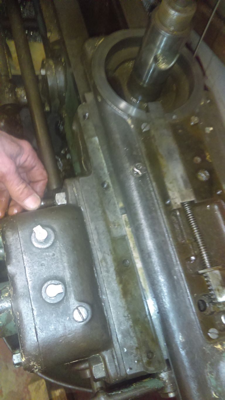
| 54 forum posts 313 photos | Home straight, just the Brake on the opposite end of the headstock from the chuck to look at, removing three deep grub screws holding the outer housing to the inner shaft reveals the brake shoe levers and the cam at the top. There's plenty of shoe left on one lever.
One missing shoe, and the three screws ! holding it in. |
| not done it yet | 09/06/2018 08:36:22 |
| 7517 forum posts 20 photos | Three screws? Am I missing something? Great job. I will stick with my hobby lathe! |
| Bob McDougall | 07/07/2018 01:08:31 |
| 54 forum posts 313 photos | New brake pads fitted by Villiers Services in Birmingham . nice job £19.50. re fitting the drum . should have been easy........ first fit. the cam arm was in the wrong position. second fit , the cam arm was in the wrong position. at this point we realised the cam arm was on a spline that had moved during the origional dissasembly. what we thought was a 10 minute job is now next weeks job. She is hard mistress.
Edited By Bob McDougall on 07/07/2018 01:11:03 |
| Meunier | 07/07/2018 15:31:46 |
| 448 forum posts 8 photos | NDIY, only a guess under the muck in 1st pic/08Jun, think the third screw could be a 'top-hat' shouldered screw acting as a pivot point for the 2shoes, up by the spring. as you say, great job. |
| Bob McDougall | 12/10/2018 22:31:28 |
| 54 forum posts 313 photos | Found an assembly error on the capstan feed that makes the feed jam. There is an arm inside the capstan saddle that engages with the capstan turret lower sprocket to push the head to its nest location. There is a button which can move this lever out of position so the turret doesnt auto turn when you move the mechanism back. This lever has an underside peg which needs to be on the INSIDE of the flanged button rod. we assembled it on the outside and it worked for a while then jammed. Image 1 is the outside button, image 2 is the lever in its incorrect position outside the plunger head. it should be on the inside. . After we fixed it we drilled 1 inch holes in 5mm steel plate with no pilot drill. Nice.
|
| Neil Wyatt | 13/10/2018 09:33:41 |
 19226 forum posts 749 photos 86 articles | Posted by not done it yet on 09/06/2018 08:36:22:
Three screws? Am I missing something? Great job. I will stick with my hobby lathe! A look at the 'fitted' photo shows three holes in the lever that shoudl be for (presumably recessed brass) screws to hold missing the pad in place. |
| Bob McDougall | 19/10/2018 23:10:35 |
| 54 forum posts 313 photos | three screws, not sure this is the right post. Latest problem is the capstan slide is so worn it sits low centre height by about 1mm. so thinking of shimming the whole capstan head rather than the slide.
|
| Kevin Rourke | 05/01/2019 19:59:24 |
| 1 forum posts | Just read this thread after agreeing to adopt a 2a this evening. Great job on the restoration fair play to you!
Did you manage to get a copy of the manual, would really appreciate a copy if you had one?
|
| Bob McDougall | 07/03/2019 23:59:10 |
| 54 forum posts 313 photos | Wear on the auxilliary Capstan slide has become apparent! . a centre drill is about 30 tho below centre. . The majority of the wear is on the lower section but the upper capstan slider has some signs of wear also. The wear appears to be front heavy so the whole capstan carrige is tilted forward and lower. the wear from where the gibb strip was located to the moving upper capstan section.
also wear of the capstan head into the capstan saddle.
on bothe sides
ANY options appreciated. our thoughts are, moglice or equivalent. Scrape the capstan slider (top bit) flat , cut down the capstan saddle (bottom bit fixed to the bed) and moglice it. but we will still be down due to the turret wear. but we could shim the turret up as its wear appears even but not sure if it is because of the cutting direction you would expect more wear on the frontside ? Anyone around SN16 would apperciate help. we have got this far but we are not precision engineers. Have purchased a surface plate and 1" wide cast iron bar to make a straight edge and will run a dial indicator over all the parts we can to get an idea of wear. next post might be in scraping.lol. |
| David George 1 | 08/03/2019 07:10:52 |
 2110 forum posts 565 photos | Hi have a look at Turcite. It can be glued and screwed to slideway parts and is a permanent repair but will need machining etc. David |
| Bob McDougall | 09/03/2019 00:51:00 |
| 54 forum posts 313 photos | Hi David, yes we are looking at all options, what we are unsure about is just what acuracy is needed in the capstan head. clearly this machine was used to the point when we now have it so it was making parts even with this wear so if we can gain 90% of the origional acurracy . is that good enough. ? What is the effect of a low center height capstan head ? my thoughts are ,a centre drill will cut an off centre hole. a drill will cut a taper If we know these faults can we compensate for them ? any hole over drill size is cut by the borijng tool so no problem small drills will bend to adapt to the centre drill hole. ???
|
| Howard Lewis | 10/03/2019 09:09:42 |
| 7227 forum posts 21 photos | As you say, an off centre capstan will result bin inaccurate work. A Roller box, having been set to metal turned with a toll in the toolpost, will then cut off centre and probably produce undersize and / or tapered, IF the rollers will enter on the job. And, probably the wear is not even, so the capstan will actually be inclined, and be even more likely to produce a taper. Sounds like the fault needs to be corrected by whatever means, mill back to level and then fit packing to return to design dimension. (Raglan lathes had hardened ways which were bolted to the bed, so that they could be replaced when when worn. So, a similar technique seems needed here ) Keep up the good work. You will have a good solid machine when all is finished. Howard |
| James Tarff | 05/12/2020 19:11:43 |
| 1 forum posts | Hi there could you inform me witch way the Hoffman N1055 bearings go I took my A2 to bits some year ago then I fell ill and I’m just now getting back to doing the job I like and not the jobs I have to .my memory as taken a hit but I need to make sure .Are the bearings face to face in the or face to back .On the Hoffman bearings the it as the bearing information and the word thrust .My head is telling me to put one bearing with the thrust facing the chuck then the spacers and the second bearing with the thrust facing the spindle nuts on the brake.I hope that someone can help as I would love to rebuild this old girl |


Please login to post a reply.
Magazine Locator
Want the latest issue of Model Engineer or Model Engineers' Workshop? Use our magazine locator links to find your nearest stockist!
Sign up to our Newsletter
Sign up to our newsletter and get a free digital issue.
You can unsubscribe at anytime. View our privacy policy at www.mortons.co.uk/privacy
Latest Forum Posts
- *Oct 2023: FORUM MIGRATION TIMELINE*
05/10/2023 07:57:11 - Making ER11 collet chuck
05/10/2023 07:56:24 - What did you do today? 2023
05/10/2023 07:25:01 - Orrery
05/10/2023 06:00:41 - Wera hand-tools
05/10/2023 05:47:07 - New member
05/10/2023 04:40:11 - Problems with external pot on at1 vfd
05/10/2023 00:06:32 - Drain plug
04/10/2023 23:36:17 - digi phase converter for 10 machines.....
04/10/2023 23:13:48 - Winter Storage Of Locomotives
04/10/2023 21:02:11 - More Latest Posts...
- View All Topics
Support Our Partners


Shopping Partners
Subscription Offer

Latest "For Sale" Ads
- Reeves** - Rebuilt Royal Scot by Martin Evans
by John Broughton
£300.00 - BRITANNIA 5" GAUGE James Perrier
by Jon Seabright 1
£2,500.00 - Drill Grinder - for restoration
by Nigel Graham 2
£0.00 - WARCO WM18 MILLING MACHINE
by Alex Chudley
£1,200.00 - MYFORD SUPER 7 LATHE
by Alex Chudley
£2,000.00 - More "For Sale" Ads...
Latest "Wanted" Ads
- D1-3 backplate
by Michael Horley
Price Not Specified - fixed steady for a Colchester bantam mark1 800
by George Jervis
Price Not Specified - lbsc pansy
by JACK SIDEBOTHAM
Price Not Specified - Pratt Burnerd multifit chuck key.
by Tim Riome
Price Not Specified - BANDSAW BLADE WELDER
by HUGH
Price Not Specified - More "Wanted" Ads...
Get In Touch!
Do you want to contact the Model Engineer and Model Engineers' Workshop team?
You can contact us by phone, mail or email about the magazines including becoming a contributor, submitting reader's letters or making queries about articles. You can also get in touch about this website, advertising or other general issues.
Click THIS LINK for full contact details.
For subscription issues please see THIS LINK.
Digital Back Issues


Donate

 Register
 Log-in
Model Engineer Magazine
- Percival Marshall
- M.E. History
- LittleLEC
- M.E. Clock

ME Workshop
- An Adcock
- & Shipley
- Horizontal
- Mill

Subscribe Now
- Great savings
- Delivered to your door

Pre-order your copy!
- Delivered to your doorstep!
- Free UK delivery!
All Forum Topics > Workshop Tools and Tooling > ward 2A lathe