Forum sponsored by:

Mill knee driving with a stepper
| Ian P | 06/09/2014 09:09:26 |
 2747 forum posts 123 photos | Posted by Michael Gilligan on 06/09/2014 08:47:53:
Posted by TrevorG on 05/09/2014 23:53:06:
It would be nice to accelerate more slowly unfortunately this involves running at low speeds which gets us back to square 1 . ... Which is why I mentioned the possibility of using a worm gearbox. MichaelG. A worm and pinion would work but the reduction ratio will probably be far too high. I suspect the best compromise will be in the region of 2:1 to 5:1 which is outside the worm and pinion practical range. Ian P |
| Ian P | 06/09/2014 09:22:13 |
2747 forum posts 123 photos | Les I have a couple of questions (I know this is hijacking Trevor's thread a bit) but the 8Mhx crystal seems to work perfectly well. I do have stock of 10MHz crystal modules but as the PIC is configured for a basic crystal I am not sure it would accept a rectangular waveform (and on which input pin anyway!) The stepper driver I am using has a 'Decay' configuration settings of between 0 and 100%. I don't fully understand what it does and what I should set it to. Regarding setting the stepper current value, do I just set it to the value shown on the motor data sheet? Ian P |
| John McNamara | 06/09/2014 09:35:11 |
 1377 forum posts 133 photos | Hi Trevor G A number Commercial CNC Machines particularly the bigger ones have counterbalanced Z axis carriages often using a weight and cable or chain. The weight is usually buried in the column so you don't see it. Fadal for instance **LINK** I made CNC router using toothed belts for the X and Y drive, it works well. Some images here a couple of lines down. Gear train From the above link: You may have to resize the design to accommodate the weight of the Z axis on your machine. Note the motor shaft only had to carry an axial load via the coupling which drove a shaft supported in inexpensive flanged ball bearings clamped to the side plates. This machine works very well there is very little backlash. If you can read a DXF file can send a cad file. Regards Edited By John McNamara on 06/09/2014 09:35:51 |
| Neil Wyatt | 06/09/2014 09:35:36 |
 19226 forum posts 749 photos 86 articles | Hi Ian, Check the PIC data sheet, usually one of the two crystal connections will be usually suitable for inputting an external clock signal. Neil |
| Ian P | 06/09/2014 09:39:40 |
2747 forum posts 123 photos | Posted by Neil Wyatt on 06/09/2014 09:35:36:
Hi Ian, Check the PIC data sheet, usually one of the two crystal connections will be usually suitable for inputting an external clock signal. Neil Neil True, but when programming a PIC there are options to configure the PIC inputs to suit the type of clock device. The PIC I have is already programmed for a basic crystal. Ian P |
| Michael Gilligan | 06/09/2014 09:50:33 |
 23121 forum posts 1360 photos | Posted by Ian Phillips on 06/09/2014 09:09:26:
A worm and pinion would work but the reduction ratio will probably be far too high. I suspect the best compromise will be in the region of 2:1 to 5:1 which is outside the worm and pinion practical range. Ian P .
MichaelG. |
| Les Jones 1 | 06/09/2014 10:11:00 |
| 2292 forum posts 159 photos | Hi Ian. Les. |
| John Haine | 06/09/2014 10:34:46 |
| 5563 forum posts 322 photos | Trevor, sorry, more questions...
i have a theory... Steppers have a sinusoidal torque vs displacement curve, at least at low speeds. When one winding is energised and the other isn't, at zero displacement the torque is zero, as the displacement increases to 0.9 degrees it rises to a maximum then decreases to zero at 1.8 degrees. When both windings are energised, the curve moves along 0.9 degrees so the load sees maximum torque and should move 0.9 degrees; then the first winding is switch off and the curve moves along another 0.9 degrees; then the first is energised in the opposite sense to move another 0.9...and so on. With microstepping, instead of the the windings being either on+, on-, or off, the currents are modulated to move the torque curve by a fraction of a step per input step, but this means that the torque increment per step is much smaller. If stiction is too large then the load won't start to move until several micro steps have been accumulated, when hopefully it might catch up but if the total number of steps is too small it might not. This would be consistent with your observation that increasing the current, and therefore the maximum torque, decreases the speed where the problem occurs. My suspicion is that you need to increase the torque and decrease any possible stiction. Minimum microstepping will increase the torque increment. Ideally have a toothed belt reduction to increase torque and give better resolution rather than depend on microstepping. A counterbalance is an elegant engineering solution to reduce load on the screw, and I have thoughts swirling in my brain of an active counterweight with a worm geared dc motor driving a drum to take up a steel cable, with a micro switch sensing cable tension and controlling the motor. Compact, constant lift, easily adjustable.
John.
|
| Neil Wyatt | 06/09/2014 11:10:36 |
19226 forum posts 749 photos 86 articles | Hi Ian, I've checked the datasheet for the PIC16F87X and as far as I can see it will just work as long as you use the CLKIN pin and not CLKOUT. You won't do any harm by trying it. The input is a schmitt trigger so teh wave shape is unimportant, in fact the external clock spec is essentially for it to be good square wave between 'DC' and Fmax. Neil
|
| jason udall | 06/09/2014 12:23:31 |
| 2032 forum posts 41 photos | Just a thought.. If you have the stepper coupled already. .a simple test of low speed drive with an added counter weight will prove illuminating. It should be a simple test to try. The case of no movement at low rate but acceptable at medium to high speed .
Consider the case if pushing a barrel up a ramp with a rifle shot... Bang pause bang pause... This is what the stepper is doing... So if the barrel rolls back to start position during the pause...result no net movement...... Increase the rate of fire.....and you reach a point where the barrel will progress... I think this might explain the behaviour... The motor obviously develops enough torque ( it has sufficient at high speed)...But some part of the mechanical system is interfering with the result... Again simply try a counter weight...they are popular in industrial solutions |
| David Colwill | 06/09/2014 15:37:48 |
| 782 forum posts 40 photos | Hi, When I converted my bridgeport clone I had the same dilemma. I opted like you to keep the old screw and as a temporary job stuck a 34 size motor via a 2:1 reduction straight on to the shaft that takes the crank handle. I used drivers that connect straight into the mains. I have run this reliably at 1500 mm / min with no gas struts or counter weights. I have never experienced any problems at low feed rates. The machine has a DRO fitted that is completely independent of the CNC and the accuracy is in the order of .02mm which is more than good enough for my purposes. In your shoes I would certainly try gearing via a toothed belt as I know it works. Regards. David. Ps I have no plans to alter the set up other than to fit belt guards. |
| TrevorG | 06/09/2014 16:21:48 |
 34 forum posts 10 photos | Posted by John Haine on 06/09/2014 08:41:59: Your observation that everything seems to work with high feed rate with no missed steps seems inconsistent with the knee not moving at all at low rates. A high rate has to start somewhere after all! I agree totally. Trying to get my head around this inconsistency is what drove me to raise this issue in the first place. Its not just being unable to understand what is going on. It is that feeling that I am missing something important that will come back to haunt me later in the project. Answers to the questions about my configuration. One thing I omitted to say earlier on is that the problem only occurs when raising the table. Lowering it is fine. So the issue is definitely load related. Sorry I thought I had mentioned it but checking back I don't seem to. I will try putting a scope on the motor drive waveform. I did this when I first bench tested the stepper off-load. With PWM mush the result was unhelpfull. May be better with the motor underload. Trevor
|
| TrevorG | 06/09/2014 16:28:10 |
34 forum posts 10 photos | Posted by David Colwill on 06/09/2014 15:37:48:
Hi, When I converted my bridgeport clone I had the same dilemma. I opted like you to keep the old screw and as a temporary job stuck a 34 size motor via a 2:1 reduction straight on to the shaft that takes the crank handle. I used drivers that connect straight into the mains. I have run this reliably at 1500 mm / min with no gas struts or counter weights. I have never experienced any problems at low feed rates. The machine has a DRO fitted that is completely independent of the CNC and the accuracy is in the order of .02mm which is more than good enough for my purposes. In your shoes I would certainly try gearing via a toothed belt as I know it works. Regards. David. Ps I have no plans to alter the set up other than to fit belt guards. Interesting. As stated above the effective leadscrew rate between the handle and the knee on my machine is 8tpi. I would be interested to know the value for your bridgeport clone. WhileI suspect your knee is heavier than mine it should be close enough to be helpful. Trevor |
| Les Jones 1 | 06/09/2014 17:40:36 |
| 2292 forum posts 159 photos | Hi Trevor, Les. Edited By Les Jones 1 on 06/09/2014 17:41:13 |
| Les Jones 1 | 06/09/2014 18:18:05 |
| 2292 forum posts 159 photos | Hi Trevor, Les. |
| jason udall | 06/09/2014 18:26:47 |
| 2032 forum posts 41 photos | ....lowering is fine. ....really. ..you do surprise me... Sorry but didn't you read my suggestion above a bout the possible mechanism.... What you have is the "barrel" .rolling back before the next shot moves it any further up the slope.. In this case the small ( but real) back drive of the table weight on the acme jack screw..is smaller than the step...and what you get is the stepper impulses the machine up...it moves under drive..coasts..reaches max height..falls..and back drives.... With a faster pulse train you complete the next step before you end up back at step one ( excuse the pun)... So if you move down the coast is downwards...thus apearing ok If you add a counter weight you appear to reduce the gravity on the table ( mass stays the same but your upwards parabola height is increased and your limit of interstep time ( before no movement is seen) will reduce...the consequence would be to let the system work at a slower speed than now...... Again an experiment will show whether this will help If the table masses 100 kg...and 20 rpm is lowest speed achived... Hang say 20 kg over pulley..and retest...and get new lowest speed of say 5rpm...
|
| jason udall | 06/09/2014 18:29:03 |
| 2032 forum posts 41 photos | Btw on my cva I too find moving the knee down easier than up
|
| TrevorG | 06/09/2014 21:55:59 |
34 forum posts 10 photos | Hi Jason, I think with the number of posts I was going through I missed the point you were making. As you say it does explain the rather strange symptoms I have observed. Implicit in this explanation is the idea that the torque used to drive the motor is greater than the holding torque. While I don't find this too surprising it suggests a hole in my understanding of stepper motors. At this stage I want to go through the reference that Les has provided. Then I want to think my way through the whole issue. I knew my understanding of microstepping was poor. To that I need to add the whole issue of how torque varies throughout a step. As for a counter weight the problem is how to attach it to the mill so that it does not just tear itself apart. The shape of the mill itself does not easily lend itself to such a system. With the masses involved a quick suck it and see experiment is probably not a good idea. Trevor |
| John Haine | 06/09/2014 22:42:52 |
| 5563 forum posts 322 photos | What is clear from Jones on stepping motors is that at low speeds the holding torque is the same as the maximum torque. As you drive the motor the angular position for max holding torque as a function of displacement is moved along, in steps, not impulses.
Are you using the common 2m542 drivers (these have minimum 2 micro steps)? These seem very trouble free. I doubt there is much point trying to measure the current to the motors, just swap the driver with one of the other axes and see if it behaves the same. You don't say, but I assume the other axes work fine at low speed? And have you checked raising/lowering repeatedly the knee at higher speed with a dial indicator to make sure there are no lost steps that you may not be noticing? You could also try feeding the driver from a PC parallel port with Mach 3 just to eliminate your AVR board and software.
|
| jason udall | 06/09/2014 23:53:28 |
| 2032 forum posts 41 photos | One of the things about steppers..torque falls off with "rpm" So if torque ok at 20 rpm then torque should be ok at 5 rpm If torque ok knee down at 5 rpm then torque will be the same at -5 rpm ccw vs cw This leads to a "mechanical" type problem Ok if a counter weight is not possible for test of knee move then maybe a extention spring..fixed to the quill say and clamped to the table. ..now back off the knee...to tension the spring..now tryslow up on knee..if now works you know that some help or bias would answer the question |

Please login to post a reply.
Magazine Locator
Want the latest issue of Model Engineer or Model Engineers' Workshop? Use our magazine locator links to find your nearest stockist!
Sign up to our Newsletter
Sign up to our newsletter and get a free digital issue.
You can unsubscribe at anytime. View our privacy policy at www.mortons.co.uk/privacy
Latest Forum Posts
- hemingway ball turner
04/07/2025 14:40:26 - *Oct 2023: FORUM MIGRATION TIMELINE*
05/10/2023 07:57:11 - Making ER11 collet chuck
05/10/2023 07:56:24 - What did you do today? 2023
05/10/2023 07:25:01 - Orrery
05/10/2023 06:00:41 - Wera hand-tools
05/10/2023 05:47:07 - New member
05/10/2023 04:40:11 - Problems with external pot on at1 vfd
05/10/2023 00:06:32 - Drain plug
04/10/2023 23:36:17 - digi phase converter for 10 machines.....
04/10/2023 23:13:48 - More Latest Posts...
- View All Topics
Support Our Partners


Shopping Partners
Subscription Offer

Latest "For Sale" Ads
- Reeves** - Rebuilt Royal Scot by Martin Evans
by John Broughton
£300.00 - BRITANNIA 5" GAUGE James Perrier
by Jon Seabright 1
£2,500.00 - Drill Grinder - for restoration
by Nigel Graham 2
£0.00 - WARCO WM18 MILLING MACHINE
by Alex Chudley
£1,200.00 - MYFORD SUPER 7 LATHE
by Alex Chudley
£2,000.00 - More "For Sale" Ads...
Latest "Wanted" Ads
- D1-3 backplate
by Michael Horley
Price Not Specified - fixed steady for a Colchester bantam mark1 800
by George Jervis
Price Not Specified - lbsc pansy
by JACK SIDEBOTHAM
Price Not Specified - Pratt Burnerd multifit chuck key.
by Tim Riome
Price Not Specified - BANDSAW BLADE WELDER
by HUGH
Price Not Specified - More "Wanted" Ads...
Get In Touch!
Do you want to contact the Model Engineer and Model Engineers' Workshop team?
You can contact us by phone, mail or email about the magazines including becoming a contributor, submitting reader's letters or making queries about articles. You can also get in touch about this website, advertising or other general issues.
Click THIS LINK for full contact details.
For subscription issues please see THIS LINK.
Digital Back Issues


Donate

 Register
 Log-in
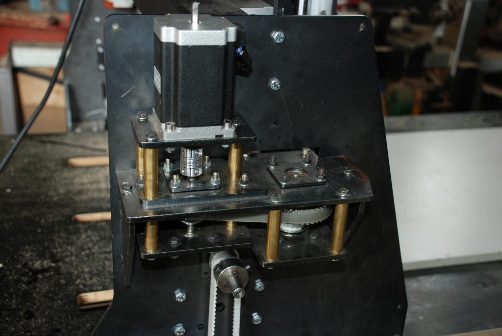
Model Engineer Magazine
- Percival Marshall
- M.E. History
- LittleLEC
- M.E. Clock

ME Workshop
- An Adcock
- & Shipley
- Horizontal
- Mill

Subscribe Now
- Great savings
- Delivered to your door

Pre-order your copy!
- Delivered to your doorstep!
- Free UK delivery!
All Forum Topics > CNC machines, Home builds, Conversions, ELS, automation, software, etc tools > Mill knee driving with a stepper