Forum sponsored by:

53 tooth gear
| Andrew Johnston | 17/11/2012 11:11:27 |
 7061 forum posts 719 photos | Ian, Neil: I admit it, I'm being an idiot. I agree that the relative accuracy does not change as the gear gets proportionately larger. I'm not quite sure what I was trying to say! As far as machining my final drive gears go, I did the sums as follows. The gears are 5DP, 72 teeth with an OD of 14.8". My dividing head has a quoted maximum error of 1 min 30 sec. I'm making an assumption that my industrial 12" rotary table is similar. I make that a maximum error of about 3 thou on the circumference of a 14.8" disc. So the tooth width could be 3 thou wider, or narrower, than theory. The rule for cutting deeper for one gear of a pair, with 20°PA, is backlash times 1.46. So that means I need to cut about 4-5 thou deeper than normal. Neil: I am intrigued as to how you measured the maximum error on your rotary table? Regards, Andrew |
| John Stevenson | 17/11/2012 12:10:26 |
 5068 forum posts 3 photos |
Posted by jason udall on 14/11/2012 23:45:34:
380 to 760 nm (400-790 TeraHertz) is generaly accepted as visable light so for rock and roll 500nm or 0.5 um (microns) will do.
Thanks anyway.
.
So will there be a difference if you cut the gear in daylight, at night with a florescent light or under under the bed covers with a torch.
Wouldn't want to get it wrong you know.
John S. |
| Nicholas Farr | 17/11/2012 14:02:02 |
 3988 forum posts 1799 photos | Hi John, just listen to a bit of rock-n-roll while your doing it and you should be OK. Regards Nick. |
| Stub Mandrel | 17/11/2012 16:21:44 |
 4318 forum posts 291 photos 1 articles | HI Andrew, I didn't measure it, I made the rash assumption my home-cut worm and wheel are accurate, and then calculated the theoretical error for being half of one division out. All the gears I have made to date using this method of divising with Ivan Law's book beside me seem to work fine.
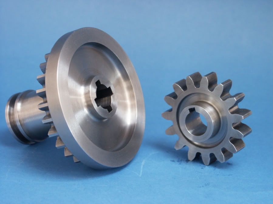
13T pinion with splined insert
My gear cutting setup, using home made rotary table/dividing head:
A pair of bevel gears made using the above equipment:
A 63-tooth metric changewheel for my mini lathe:
Regards
Neil |
| Andrew Johnston | 17/11/2012 22:46:08 |
7061 forum posts 719 photos | Neil: Thanks, I was wondering. I'm not sure how one would independently measure the position of the table, versus the dial reading. May be a test indicator on a bar on the table? If the angular changes are small enough I guess one can ignore the arc versus straight line errors.
The gears look fantastic; are the bevels parallel depth? How did you cut the splines on the pinion? I need to cut some splines for the gears that slide on the crankshaft for my traction engines. I'm prevaricating, which means I'm not sure how to go about it! The only thing is, I think the pinion shown has more than 13 teeth, surely not a dividing error!? Regards, Andrew |
| Ian S C | 18/11/2012 10:22:49 |
 7468 forum posts 230 photos | I make it 17T, the other one must be the 13T. Ian S C |
| JasonB | 18/11/2012 13:38:52 |
 25215 forum posts 3105 photos 1 articles | Andrew I cut the four splines on the Fowler by planing with the lathe but at 3/16" wide its as much as I would want to do that way.
If you make a plug for the bore of the gear with the required number of keyways in it, just like a broaching bush but with more than one slot. You can then broach the first keyway, locate the plug with a bit of key steel and then run the broach down the next keyway etc Edited By JasonB on 18/11/2012 13:39:15 |
| Andrew Johnston | 18/11/2012 17:46:36 |
7061 forum posts 719 photos | Jason: Thanks for the insights. I'll rephrase the question. I have a slotting head on the back of the Bridgeport, which is fine with a 1/4" wide keyway in cast iron. My prevarication is due to wondering how it is going to cope with a 5/16" wide spline in EN24T? And more to the point, if it cannot cope, will it simply stall, or will I end up badgering it? Regards, Andrew |
| JasonB | 18/11/2012 17:56:00 |
25215 forum posts 3105 photos 1 articles | Never tried a slotting head so can't comment on the Badgering. What about taking teh majority out in two goes with a smaller cutter and just finishing to width with the 5/16" Have you not got an EDM machine tucked away somewhere in that garage? might be lurking in a dark corner.
J Edited By JasonB on 18/11/2012 17:56:25 Edited By JasonB on 18/11/2012 17:58:15 |
| Tel | 18/11/2012 18:13:38 |
 157 forum posts 28 photos | ... or buy something like this - **LINK** and use it to lash up a simple indent type indexer. |
| Stub Mandrel | 18/11/2012 19:17:23 |
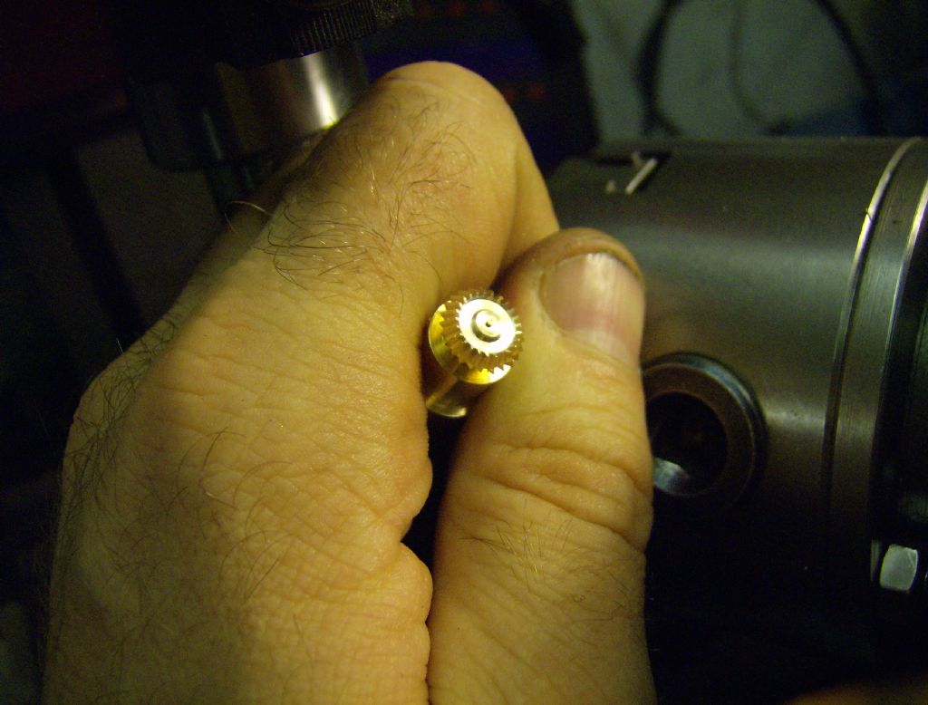
4318 forum posts 291 photos 1 articles | I cut my splines using my version of Stan Bray's slotting tool in the Workshop Practice Book. The pinions are constant-depth, again using the Ivan Law method. It works on really small gears. This is the smaller of a speed up pair for the governor of a stationary engine:
Neil |
| Andrew Johnston | 18/11/2012 21:07:09 |
7061 forum posts 719 photos | Neil: Thanks for the information on the gears. I'll have to read up on the parallel deptth method, as I need to make some small bevel gears for the governors on my traction engines. I could take out the splines in a series of steps, but I'd still like to finish with a full width cut. I want the outer edge of each spline groove to be circular so as to exactly match the crankshaft, rather than square. I guess I'll have to suck it and see. Regards, Andrew
PS: Sadly I don't have an EDM machine lurking in the garage, at least not yet. Edited By Andrew Johnston on 18/11/2012 21:07:41 |
| Stub Mandrel | 20/11/2012 10:38:05 |
4318 forum posts 291 photos 1 articles | Good question Andrew - how do you turn accurate splines and ensure the gear is a close fit on the shaft? This is how I did it (and I had to have a good look at the gearbox to find out!) The gearbox is for a 1/4 scale Forson Model F tractor, that has never got beyond the gearbox, some patterns and a lot of dreaming and drawing. I turned the gear blanks so that each has a decent boss (needed for the shifter to engage with in any case). with the boss outwards and bored right though at the diameter of the inside of the splines. I bored the boss (but not the gear (the gears are 1/4" thick, the bosses either 1/4" or 5/16" (I didn't check) over size to be a light force fit for bronze bushes made to be a close sliding fit on the gearshaft. I parted off the gears and mounted them on a mandrel to cut the gears. reversed them and cut the splines so that the grooves were a wider diameter than the shaft, but still smaller than the outside of the bush. Finally, I inserted the bushes so they butted up against the splines. The gears now slide freely aliong the shaft using the bush as a guide on the original outside diameter of the PGMS shaft. The splines only act to stop rotation. I also bushed the other gears which slide but do not have splines. Internal gears (which act as dog clutches as other gears slide into them) were not cut as proper gears, just milled-out semicircular notches. The layshafts run in ball races but all the gears just have PB bushes except the input and output gears which run in ball races and have.internal races for the ends of the layshafts. Layout and dimensions are as near the original as I could get, aside that I think the original may use a stub-tooth form. Neil
Edited By Stub Mandrel on 20/11/2012 10:41:01 |


Please login to post a reply.
Magazine Locator
Want the latest issue of Model Engineer or Model Engineers' Workshop? Use our magazine locator links to find your nearest stockist!
Sign up to our Newsletter
Sign up to our newsletter and get a free digital issue.
You can unsubscribe at anytime. View our privacy policy at www.mortons.co.uk/privacy
Latest Forum Posts
- hemingway ball turner
04/07/2025 14:40:26 - *Oct 2023: FORUM MIGRATION TIMELINE*
05/10/2023 07:57:11 - Making ER11 collet chuck
05/10/2023 07:56:24 - What did you do today? 2023
05/10/2023 07:25:01 - Orrery
05/10/2023 06:00:41 - Wera hand-tools
05/10/2023 05:47:07 - New member
05/10/2023 04:40:11 - Problems with external pot on at1 vfd
05/10/2023 00:06:32 - Drain plug
04/10/2023 23:36:17 - digi phase converter for 10 machines.....
04/10/2023 23:13:48 - More Latest Posts...
- View All Topics
Support Our Partners


Shopping Partners
Subscription Offer

Latest "For Sale" Ads
- Reeves** - Rebuilt Royal Scot by Martin Evans
by John Broughton
£300.00 - BRITANNIA 5" GAUGE James Perrier
by Jon Seabright 1
£2,500.00 - Drill Grinder - for restoration
by Nigel Graham 2
£0.00 - WARCO WM18 MILLING MACHINE
by Alex Chudley
£1,200.00 - MYFORD SUPER 7 LATHE
by Alex Chudley
£2,000.00 - More "For Sale" Ads...
Latest "Wanted" Ads
- D1-3 backplate
by Michael Horley
Price Not Specified - fixed steady for a Colchester bantam mark1 800
by George Jervis
Price Not Specified - lbsc pansy
by JACK SIDEBOTHAM
Price Not Specified - Pratt Burnerd multifit chuck key.
by Tim Riome
Price Not Specified - BANDSAW BLADE WELDER
by HUGH
Price Not Specified - More "Wanted" Ads...
Get In Touch!
Do you want to contact the Model Engineer and Model Engineers' Workshop team?
You can contact us by phone, mail or email about the magazines including becoming a contributor, submitting reader's letters or making queries about articles. You can also get in touch about this website, advertising or other general issues.
Click THIS LINK for full contact details.
For subscription issues please see THIS LINK.
Digital Back Issues


Donate

 Register
 Log-in
Model Engineer Magazine
- Percival Marshall
- M.E. History
- LittleLEC
- M.E. Clock

ME Workshop
- An Adcock
- & Shipley
- Horizontal
- Mill

Subscribe Now
- Great savings
- Delivered to your door

Pre-order your copy!
- Delivered to your doorstep!
- Free UK delivery!
All Forum Topics > Beginners questions > 53 tooth gear