Forum sponsored by:

No. of divisions
| Anthony Rhodes | 22/09/2011 17:59:50 |
| 21 forum posts 31 photos | Posted by Nobby on 22/09/2011 11:49:54:
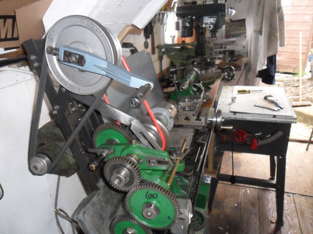
Hi Andy & Guys The gear train was no problem 40 - 60 idle- 50 leadscrew as photo .When engaging screwcutting lever photo on a test peice After disengaging lever the the 2'nd cut did not line up . On my Exe lathe I sold there was no problem . I know i can use the revering trick I have no reverse on this lathe . I suppose if I put the pedal back on I could use this trick Can I add a threading indicator some how . ? Regards Nobby Nobby,
For the dog clutch to pick up all threads reliably it has to be before any changes in ratio and have a single dog. This is how the Exe is setup and is not how the Drummond is setup.
Reversable motors are common, reverse pedalling would work, and a hand crank you insert in the back end of the spindle is another solution.
Yes, you can install a threading dial. Look at any Myford or Boxford or most other lathes to see how they are set up. Most are for 8 TPI, does have to match right hand or left hand leadscrew thread. Usually mounted on right side of apron, needs to be able to be swung into and out of engagement with the leadscrew and hold in either position. When mounting you may have to shim the dial away from the side of theapron until the graduations on the dial line up with the witness mark when the split nuts are closed.
Anthony
|
| Nobby | 23/09/2011 00:42:31 |
 587 forum posts 113 photos |
Hi Andy & Guys
It was only a short thread about 5/8" so I fitted a crank handle As Andy suggested Nobby
 Ii IiEdited By Nobby on 23/09/2011 00:43:14 |
| Anthony Rhodes | 23/09/2011 02:28:01 |
| 21 forum posts 31 photos | Posted by Nobby on 23/09/2011 00:42:31:
Hi Andy & Guys
It was only a short thread about 5/8" so I fitted a crank handle As Andy suggested Nobby
Edited By Nobby on 23/09/2011 00:43:14 Nobby,
Try "Anthony". Thanks for the photo.
Anthony |
| Nobby | 30/09/2011 23:28:35 |
587 forum posts 113 photos | Sorry Anthony Great idea saved me some trouble. Nobby |
| Anthony Rhodes | 01/10/2011 03:56:47 |
| 21 forum posts 31 photos | For those who've had dificulty understanding or visualizing the mechanism being discussed in this thread, here is a sectional drawing of a version to suit the Seig C3 lathe.
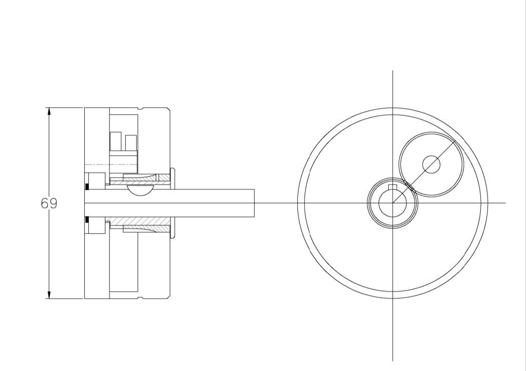 Best option is to click on the drawing, then download it for better study.
Looking at the left drawing, on the left the feed screw passes through a bearing as it extends out through the dial. Immediately to the righ of the bearing is a sleeve keyed to the spindle of the carriage handwheel on which a gear is cut. The center gear drives an outer gear on a layshaft which, via a second gear at the right end of the layshaft, passes the drive back to a aecond sleeve running on the outside of the first one. This second sleeve is attached to the micrometer dial which surounds the mechanism and thereby also serves as the housing for the mecahnism.
The unit shown is setup for metric readout but an alternative to read out in inches has already been engineered. Based on the gears provided the micrometer dial can be made to rotate faster or slower than the handwheel spindle so that instead of reading out revolutions of the handwheel it reads out distance traversed by the carriage. This can be built to read out in decimal millimeters down to 0.025 mm or decimal inches down to 0.001".
Very effective when doing precision work.
Anthony Edited By Anthony Rhodes on 01/10/2011 06:59:29 |
| Nobby | 08/05/2012 22:14:00 |
587 forum posts 113 photos |
Hi Graham |
| Ady1 | 09/05/2012 10:38:22 |
 6137 forum posts 893 photos | Yes. Lovely workmanship, it's an artform when you get good enough ...now it's back to hacking away with a knife and fork for me |
| Ady1 | 09/05/2012 23:59:29 |
6137 forum posts 893 photos | Well I've waited 24hrs and no one has said a word so it's time for Ady1 to ask Graham Are those dials in aluminium or steel? How are you marking them up so they look good?
Ady1 |
| Nobby | 23/07/2012 21:46:07 |
587 forum posts 113 photos |
Hi Gray Nobby Edited By Nobby on 23/07/2012 21:48:38 |
| Steamer1915 | 25/02/2013 12:09:01 |
 171 forum posts 42 photos | Anthony, How have you calculated the 0.866" distance for one complete revolution of the Myford handwheel? I ask this because I make it 0.8617". I arrived at this figure based on the following:- The pitch of the Myford rack is .15708" (3.1416/20dp). The apron reduction gearing is 35/16 which equals 2.1875. One turn of the 12t gear (that engages with the rack) 12 x 0.15708" =1.885". Divide this by the 2.1875 reduction and the answer comes to 0.8617". If the 28/26 gearing is applied twice the distance moved is .99936". The only assumption I have made is that the Myford rack is 20 DP but I have no reason to think it is isn't. I can't see how any of the alternative gearing that you propose, will improve the accuracy. Steve. |
| John Stevenson | 25/02/2013 14:47:11 |
 5068 forum posts 3 photos | Steve. Not had time to check your sums but I can confirm the Myford rack is 20 Dp at 14.5 degrees PA.
Edit, Steves figures make sence to me |
| Stub Mandrel | 25/02/2013 18:32:20 |
 4318 forum posts 291 photos 1 articles | Steve - thanks for bringing a thread I had missed back to life. Gray - thanks for a delightful design. I am sorely tempted to have go - have I missed a post giving the gear sizes for the C3 version? Neil |
| Steamer1915 | 25/02/2013 18:55:40 |
171 forum posts 42 photos | John,
Thanks for the confirmation about the Myford rack and checking my figures. I was starting to think that I had missed something - even more so after posting! Gray, I absolutely agree about theoretical figures as opposed to practical uses. If I have not completely fried my brain on this, a complete turn of the graduated dial (1" will actually move the carriage slightly more - in theory. I would suggest that (again, in theory) that this is a condition that will only improve as the rack and/or gears wear. So, if the carriage was moved from an unworn section of the rack, to a worn section, any error will reduce. I have one of your dials fitted to my S7 and it has transformed the lathe. I have not come across any situation where I would question it's accuracy. I need to do the 10" slip gauge check just to see where it sits on my lathe. I can certainly see why they are so popular and why so many have been sold over the years. My post was really just to question Anthony's figures and to make sure that there isn't a better iteration. After consulting gear ratio tables in Machinery's handbook, I feel sure that there isn't - or not one that would fit into the existing body. Thank you for your thoughts on this. Best regards, Steve.
Edited By Steamer1915 on 25/02/2013 18:56:19 |
| John Stevenson | 25/02/2013 21:53:56 |
5068 forum posts 3 photos | Bit hypothetical anyway.
Although the number 0.866 is fixed in peoples mind Grays calculation of (25/28) x (26/28) = 0.862245 So 0.862245 - 0.8617 = 0.000545" Just a tad more than half a thou and allowing for wind down Wilmot lane where Myfords gear cutting equipment was located we can say this is knob on. |
| Steamer1915 | 28/02/2013 22:29:19 |
171 forum posts 42 photos | Don't understand your second line John. However, I've just spent half an hour or so checking the actual measurements on my S7. I clamped a small angle plate to the bed at the headstock end and made sure it was square to the carriage travel so as to avoid sine errors. Using slip piles of various lengths between 1 and 11 inches, I was able to see that the error (such as it is) was no more than 1/2 thou per inch over all measurements. That's close enough for me. In an earlier post, I alluded to the point that I thought that the actual measurement would be slightly longer than the dial reading and this has proved to be the case. Job's a gud 'un! Steve. |
| Stub Mandrel | 05/04/2013 14:49:18 |
4318 forum posts 291 photos 1 articles | With Gray's drawings, and advice I have just finished and fitted the C3 version of his handwheel dial to my Clark CL300M, one of the 'generic' mini lathes. Important things to note for anyone trying this version are:
To my astonishment (given that I changed the gear ratio, not becauise I doubted the design) it works just as it's supposed to, with 1.002" of saddle movement for 1.000" on the dial. Here are a few pictures, but first I'd like to thank Gray, not just for his support and great design, but for encouraging me to acheive a level of fit, finish and accuracy a step up from my usual. It's not quite toolroom yet, but I think it looks OK. Neil The working parts in place:
My first attempt at a sraight knurl(!) - I cut away the numbers and re-stamped them after this was taken (the bad ones are hidden):
And finally, tehdial on place on the lathe:
|
| john fletcher 1 | 05/04/2013 19:44:36 |
| 893 forum posts | I have the copy of the above article which was published in Engineering in Minature a couple or so years.Very good. I never actually understood how the two gears on the small shaft were linked together, perhaps I've missed something ( a keyway perhaps) when reading the article. I hope Hemingway do a kit, If they do, might just lash out when at Harrogate show.Ted |
| Stub Mandrel | 05/04/2013 21:39:19 |
4318 forum posts 291 photos 1 articles | Yes Ted, I just pressed the gears on to a slightly oversize bush, using two wooden pads so the bush ended up slightly protruding from each gear. My cunning plan to ream after fitting the gears gave me a perfect push fit on the PGMS stub axle, so I had to ease it a bit with emery paper in the lathe. Neil |
| Steamer1915 | 05/04/2013 21:55:08 |
171 forum posts 42 photos | Nice work Neil. I'm sure you will soon wonder how you managed without it. Steve
|
| Steamer1915 | 21/04/2013 20:00:26 |
171 forum posts 42 photos | Here are three photos of my efforts at Gray's dial for the Myford 7 lathe. There is an Imperial and Metric version here. Steve.
|


Please login to post a reply.
Magazine Locator
Want the latest issue of Model Engineer or Model Engineers' Workshop? Use our magazine locator links to find your nearest stockist!
Sign up to our Newsletter
Sign up to our newsletter and get a free digital issue.
You can unsubscribe at anytime. View our privacy policy at www.mortons.co.uk/privacy
Latest Forum Posts
- hemingway ball turner
04/07/2025 14:40:26 - *Oct 2023: FORUM MIGRATION TIMELINE*
05/10/2023 07:57:11 - Making ER11 collet chuck
05/10/2023 07:56:24 - What did you do today? 2023
05/10/2023 07:25:01 - Orrery
05/10/2023 06:00:41 - Wera hand-tools
05/10/2023 05:47:07 - New member
05/10/2023 04:40:11 - Problems with external pot on at1 vfd
05/10/2023 00:06:32 - Drain plug
04/10/2023 23:36:17 - digi phase converter for 10 machines.....
04/10/2023 23:13:48 - More Latest Posts...
- View All Topics
Support Our Partners


Shopping Partners
Subscription Offer

Latest "For Sale" Ads
- Reeves** - Rebuilt Royal Scot by Martin Evans
by John Broughton
£300.00 - BRITANNIA 5" GAUGE James Perrier
by Jon Seabright 1
£2,500.00 - Drill Grinder - for restoration
by Nigel Graham 2
£0.00 - WARCO WM18 MILLING MACHINE
by Alex Chudley
£1,200.00 - MYFORD SUPER 7 LATHE
by Alex Chudley
£2,000.00 - More "For Sale" Ads...
Latest "Wanted" Ads
- D1-3 backplate
by Michael Horley
Price Not Specified - fixed steady for a Colchester bantam mark1 800
by George Jervis
Price Not Specified - lbsc pansy
by JACK SIDEBOTHAM
Price Not Specified - Pratt Burnerd multifit chuck key.
by Tim Riome
Price Not Specified - BANDSAW BLADE WELDER
by HUGH
Price Not Specified - More "Wanted" Ads...
Get In Touch!
Do you want to contact the Model Engineer and Model Engineers' Workshop team?
You can contact us by phone, mail or email about the magazines including becoming a contributor, submitting reader's letters or making queries about articles. You can also get in touch about this website, advertising or other general issues.
Click THIS LINK for full contact details.
For subscription issues please see THIS LINK.
Digital Back Issues


Donate

 Register
 Log-in
Model Engineer Magazine
- Percival Marshall
- M.E. History
- LittleLEC
- M.E. Clock

ME Workshop
- An Adcock
- & Shipley
- Horizontal
- Mill

Subscribe Now
- Great savings
- Delivered to your door

Pre-order your copy!
- Delivered to your doorstep!
- Free UK delivery!
All Forum Topics > Manual machine tools > No. of divisions