Forum sponsored by:

A New Dividing Plate for my Dividing Head
| Anthony Rhodes | 06/08/2011 02:51:43 | ||||||
| 21 forum posts 31 photos | Posted by John Stevenson on 08/07/2011 19:33:47:
JP,
I did put a smiley at the end of my post.
As regards your numbers any would do but the higher the better for the odd chance that one large number will not break down lower.
As regards other number, and you may be lacking in space but 63, 127 and 25 come t mind.63 and 127 for metric translation gears and 25 because believe it or not a dividing head can't do 125 divisions or 250 divisions without a 25 hole circle.
125 or 250 is very common on feed screws with 8 or 4 tpi again very common on older British machines.
John S. John,
The numbers I want are:
127 inch-metric converion
113 pi
77 pi
71 pi
51 pi
50 pi and many others
Pi for DP and modular pitches.
71/113 = .62832 = .200000017 pi
77/25 x 51/50 = 3.1416 = 1.000002338 pi ~
63 would be OK too.
Anthony | ||||||
| maurice (Mo) Hardy | 13/10/2012 15:46:25 | ||||||
| 1 forum posts | I have been doing some meccano model work and considered making some odd gear sizes. I have a corel draw program and am using it to produce a dividing plate for a dividing head. It looks easy to use the corel draw tools to draw the plate and when I print it out it comes to the right measurements. I was thinking i could stick the printout to a metal plate and centre punch the holes using it as a template. any small errors would be further reduced by the 60-1 ratio on the headstock. | ||||||
| Chris Pattison 1 | 16/03/2015 19:33:09 | ||||||
| 21 forum posts | To have a plate with suitable hole pitches, I would start looking at having one made in MDF using a laser cutter. I would expect that these holes would be precisely spaced. This would then be used as a template to manufacture the plate in steel. | ||||||
| John Olsen | 17/03/2015 02:00:43 | ||||||
| 1294 forum posts 108 photos 1 articles | If you make a plate by any method that comes to hand, then use it with geared dividing head or rotary table to make another plate, the errors will be divided by the ratio of the worm. Practically this means that you could mark out the first plate by almost any means and the second plate would be pretty good. So ideas like printing out a CAD diagram and then spotting through would be fine. I did make a conversion for my Vertex BS0 dividing head to do differential dividing, so I can do just about any number that takes my fancy. I was asked by a previous editor of ME to write up an article but then the editor changed and I think the article was binned. Along with about three others. John | ||||||
| Michael Gilligan | 17/03/2015 08:35:36 | ||||||
 23121 forum posts 1360 photos | Posted by John Olsen on 17/03/2015 02:00:43:
If you make a plate by any method that comes to hand, then use it with geared dividing head or rotary table to make another plate, the errors will be divided by the ratio of the worm. Practically this means that you could mark out the first plate by almost any means and the second plate would be pretty good. ... . John, You make an excellent point; and this method is entirely adequate for most general engineering work. [We live in wonderful times, when we can leverage the precision of mass-produced items to serve our craft.] I think it worth just noting that in some fields [Astronomy and Surveying spring to mind], the requirements for accuracy and repeatability of circular dividing far exceed our own. ... and their quest for perfection almost defines the concept of 'Diminishing Returns'. I don't want to labour the point here, but anyone interested could investigate "Periodic Error Correction" as applied to the tracking of telescope mounts. MichaelG. | ||||||
| Neil Wyatt | 17/03/2015 09:07:36 | ||||||
 19226 forum posts 749 photos 86 articles | > Practically this means that you could mark out the first plate by almost any means and the second plate would be pretty good. .. The accuracy of the second plate would be largely limited by the accuracy of the gears. The maximum error would be: max error in worm + max error in gear + (max error in plate/number of teeth in gear) After one cycle of making plates, the error in the gear is likely to be the largest of these. The worm would have to be very poor to have a large error as you are always using the same short section of the thread, but a gear can have a significant maximum angular error between two teeth without it being very noticeable. The chart below shows errors in a hobbed gear I made - a maximum of 1.1 degrees error!
This was made by indexing the gear around while attached to a digital level, my (rash?) assumption is that the level is more accurate than the gear. Neil
Edited By Neil Wyatt on 17/03/2015 09:17:32 | ||||||
| Michael Gilligan | 17/03/2015 11:44:54 | ||||||
23121 forum posts 1360 photos | Posted by Neil Wyatt on 17/03/2015 09:07:36:
... shows errors in a hobbed gear I made - a maximum of 1.1 degrees error! ... This was made by indexing the gear around while attached to a digital level, my (rash?) assumption is that the level is more accurate than the gear. . A very rash assumption, I would say, Neil [unless, of course, you have an extraordinarily precise digital level] MichaelG. | ||||||
| John Olsen | 17/03/2015 12:56:08 | ||||||
| 1294 forum posts 108 photos 1 articles | Well, I just have to hope that the one in my Vertex is better than that since it is kind of tricky to check. I don''t even have a digital level. All I know is that the gears I have cut have run OK together for the sort of service I have required. Nothing all that arduous, just 20DP wheels for a gearbox for the Myford. Incidently I started that project because the thousand pounds or so for the real one sounded expensive...having finished the project it looks more like a bargain! People worry about gearcutting but that was the easy part of the project. John | ||||||
| Michael Gilligan | 17/03/2015 13:03:55 | ||||||
23121 forum posts 1360 photos | Posted by John Olsen on 17/03/2015 12:56:08:
... I don''t even have a digital level. . That probably puts you at a considerable advantage, John MichaelG. | ||||||
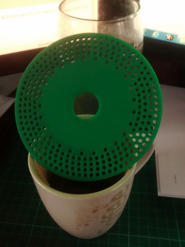
| John Stevenson | 17/03/2015 16:02:24 | ||||||
 5068 forum posts 3 photos | Posted by Chris Pattison 1 on 16/03/2015 19:33:09:
To have a plate with suitable hole pitches, I would start looking at having one made in MDF using a laser cutter. I would expect that these holes would be precisely spaced. This would then be used as a template to manufacture the plate in steel. .
Perspex would be better as the quality is higher. Lasers just love perspex.
Nothing special, just an old file I found and translated to the laser. Right hand half is clean as the bit of scrap still had some of the backing paper on. LH half shows some discolouration due to the paper being missing but the quality is good and consistent.
Cutting time was about 4 to 5 minutes, didn't check as walked away to do something else. | ||||||
| Neil Wyatt | 17/03/2015 17:32:51 | ||||||
19226 forum posts 749 photos 86 articles | > A very rash assumption, I would say, Neil Well the Wixey website says:
I'm happy to accept that mine is equally accurate. I can vouch for the repeatability and +/- 0.2 degrees is better than +/1 0.6 degrees. Neil | ||||||
| Mike Poole | 17/03/2015 18:53:08 | ||||||
 3676 forum posts 82 photos | I thought this was a pretty clever idea
Mike | ||||||
| John Olsen | 17/03/2015 19:26:45 | ||||||
| 1294 forum posts 108 photos 1 articles | I was told once that a somewhat related technique was used to construct accurate leadscrews in the early days. They wound wire around long mandrel to form a kind of thread, and then cast a lead nut around it. This can apparently give a very accurate pitch since wire can be drawn in long lengths with a very consistent diameter. The diameter is determined by the size of the hole in the die, so provided that does not wear significantly while drawing the wire, the diameter will be constant. The pitch will only depend on the diameter of the drawn wire, although for mechanical reasons the mandrel should have a constant diameter too. Such an arrangement is not ideal for long term use but is fine for making some master leadscrews. John | ||||||
| Michael Gilligan | 17/03/2015 22:11:13 | ||||||
23121 forum posts 1360 photos | Posted by Neil Wyatt on 17/03/2015 17:32:51:
> A very rash assumption, I would say, Neil Well the Wixey website says:
I'm happy to accept that mine is equally accurate. I can vouch for the repeatability and +/- 0.2 degrees is better than +/1 0.6 degrees. Neil . Neil, I can see no reason why a hobbed gear should be that bad. The hobbing process should automatically even-out most errors. Did you re-mount the gear, between cutting it and measuring it ? ... If so, then I suspect that some of your recorded errors might be from eccentricity in the mounting [it's surprising how much angular error can be produced by a few thou' offset]. MichaelG. | ||||||
| Nigel McBurney 1 | 18/03/2015 10:04:56 | ||||||
 1101 forum posts 3 photos | Reading back through this topic,which is quite old ,one post mentioned a straight tooth gear slipping and producing a thin tooth, gear slippage on the mandrel can be caused by a cutter being sharper on side, than the other. Usually caused by the cutter rubbing on a hard spot on a previous job (,a lot of cutters used today second hand bought from auction or other sources ,most are good but some can be damaged,) the blunt side pushes away from the work and the sharp side cuts deeper, a can move the workpiece particularly if the gear is on maximum capacity of the dividing head. It does pay to mark the first tooth ,and check the gear when finished ,a gear tooth vernier is ideal for his task. Very often an awful lot is discussed about theory of dividing methods and accuracy ,but very little about the work set up accuracy ie mandrels and work holding ,correct cutter sharpening,and checking of the finished product. | ||||||
| Neil Wyatt | 18/03/2015 14:46:58 | ||||||
19226 forum posts 749 photos 86 articles | > They wound wire around long mandrel to form a kind of thread, and then cast a lead nut around it. Two wires, then you unwind one of them to leave a basic, but reasonably accurate, thread. Neil | ||||||
| Neil Wyatt | 18/03/2015 14:50:38 | ||||||
19226 forum posts 749 photos 86 articles | > I can see no reason why a hobbed gear should be that bad. I can - I should have pointed out that it was free hobbed. The first one had an extra tooth, despite being gashed. I think the cause was insufficiently deep gashing. Neil | ||||||
| Harold Hall 1 | 18/03/2015 21:18:27 | ||||||
| 418 forum posts 4 photos | I have used the method suggested by Maurice (Mo) with satisfactory results, actually providing an article in issue 8 of MEW regarding the method. It's first use was to produce a plate having 125 holes. However, I did not have a computer and asked the draughtsman in my department to produce a printout. It was printed using pen plotter onto film and was very accurate. Subsequently, when I had acquired a PC with a CAD program I printed out my own using dot matrix, inkjet and laser printers. With these, I have always found that the large circle on which the divisions are placed is very slightly oval, typically an error of 0.5mm on a 100mm circle. Whilst this would have minimal effect on the accuracy of the divisions, the detent on my dividing heads could not cope with this. Rather than go into detail here, my solution to this can be seen in Photo 16 and associated text. I have also used the method of producing the plate on the milling machine using the coordinates for each hole to position them, as implied by the use of CNC and DRO's mentioned by some above. Unfortunately, most will not have these facilities available and for them my pages on placing holes on a PCD may be helpful. These basically use the method implied by John S when he started one of his comments by saying Rough and ready Excel spreadsheet." For my coordinate source I use the minimum X and Y values making it outside the circle on which the divisions are being set. This can be seen on __SK 2.__ and ensures that all calculated values are positive making it easier to work with than if using the method in ___SK 1.__
See the article "Holes on a PCD, The Mathematical Method" for more detail
Harold
| ||||||
| daveb | 18/03/2015 23:42:47 | ||||||
| 631 forum posts 14 photos | Posted by John Stevenson on 11/07/2011 21:52:29:
Posted by Andrew Johnston on 11/07/2011 19:47:42:
the starting angle (with 9 o'clock being zero)
Regards,
Andrew
Mine must be on British summer time as zero is at 3 o'clock.
I wonder if this is caused by the X axis designations (- +) being reversed, on many DRO systems these are selected on initial set-up.
Dave
Edited By daveb on 18/03/2015 23:44:04 | ||||||
| Dave Martin | 19/03/2015 18:07:14 | ||||||
| 101 forum posts 11 photos | Posted by John Stevenson on 17/03/2015 16:02:24:
By'eck - if that's the size of your tea strainer John, what size HobNobs are you on now? |


Please login to post a reply.
Magazine Locator
Want the latest issue of Model Engineer or Model Engineers' Workshop? Use our magazine locator links to find your nearest stockist!
Sign up to our Newsletter
Sign up to our newsletter and get a free digital issue.
You can unsubscribe at anytime. View our privacy policy at www.mortons.co.uk/privacy
Latest Forum Posts
- *Oct 2023: FORUM MIGRATION TIMELINE*
05/10/2023 07:57:11 - Making ER11 collet chuck
05/10/2023 07:56:24 - What did you do today? 2023
05/10/2023 07:25:01 - Orrery
05/10/2023 06:00:41 - Wera hand-tools
05/10/2023 05:47:07 - New member
05/10/2023 04:40:11 - Problems with external pot on at1 vfd
05/10/2023 00:06:32 - Drain plug
04/10/2023 23:36:17 - digi phase converter for 10 machines.....
04/10/2023 23:13:48 - Winter Storage Of Locomotives
04/10/2023 21:02:11 - More Latest Posts...
- View All Topics
Support Our Partners


Shopping Partners
Subscription Offer

Latest "For Sale" Ads
- Reeves** - Rebuilt Royal Scot by Martin Evans
by John Broughton
£300.00 - BRITANNIA 5" GAUGE James Perrier
by Jon Seabright 1
£2,500.00 - Drill Grinder - for restoration
by Nigel Graham 2
£0.00 - WARCO WM18 MILLING MACHINE
by Alex Chudley
£1,200.00 - MYFORD SUPER 7 LATHE
by Alex Chudley
£2,000.00 - More "For Sale" Ads...
Latest "Wanted" Ads
- D1-3 backplate
by Michael Horley
Price Not Specified - fixed steady for a Colchester bantam mark1 800
by George Jervis
Price Not Specified - lbsc pansy
by JACK SIDEBOTHAM
Price Not Specified - Pratt Burnerd multifit chuck key.
by Tim Riome
Price Not Specified - BANDSAW BLADE WELDER
by HUGH
Price Not Specified - More "Wanted" Ads...
Get In Touch!
Do you want to contact the Model Engineer and Model Engineers' Workshop team?
You can contact us by phone, mail or email about the magazines including becoming a contributor, submitting reader's letters or making queries about articles. You can also get in touch about this website, advertising or other general issues.
Click THIS LINK for full contact details.
For subscription issues please see THIS LINK.
Digital Back Issues


Donate

 Register
 Log-in
Model Engineer Magazine
- Percival Marshall
- M.E. History
- LittleLEC
- M.E. Clock

ME Workshop
- An Adcock
- & Shipley
- Horizontal
- Mill

Subscribe Now
- Great savings
- Delivered to your door

Pre-order your copy!
- Delivered to your doorstep!
- Free UK delivery!
All Forum Topics > Workshop Techniques > A New Dividing Plate for my Dividing Head