Forum sponsored by:

Metal fatigue and clock making
Mild steel clock frame - how to overcome metal fatigue
| Nicholas Farr | 20/12/2010 12:16:25 |
 3988 forum posts 1799 photos | Hi Terry and John, the point about about stress consentration points is a valid one. During my colleage welding course work we had to cut a 1" section at right angles to a butt weld using a low heat and non pressure input cutting technique, i. e. a hacksaw. this section was then given the bend test, which was a U bend round a round former. I can't remember the ratio of the former diameter to the plate thickness, but it was about 25mm for a 3mm thickness. The weld bead had to at the very bottom of the U shape. The test piece had to bend without breaking or any sine of cracking to pass as being a sound weld. The test piece preperation was to file tyhe weld flat to the plate and along the egdes over a longer length to that which the bend required, this also included rounding off the edges and ensuring that there were not even the smallest nicks present. Scratches, however in this situation was not a real concern. It was proved that sharp edges and hacksaw marks propagated cracks and falure by taking two test pieces from the same section of the same weld and preparing one as specified and one leaving it with sharpe corners and small hacksaw marks and while the one correctly prepared passed the test the other produced cracks or even fractured, this was of course if your weld was a good one in the first place.
Fractures do indeed occur along the grain boundry. The term normalising is usually refered to the heat treatment that gives a metal the finest grain structure possible and is subject to a control temp/time and metal content ratio. If a metal is heated above or longer than this critical area, grain growth forms. The larger the grain is, the weaker the metal is.
Bright steel which has been cold rolled has an elongated grain structure along the path of the rolling process. The lenth of elongation deminishes to is central section, which as Terry says is stressed and as you will find that if you machine off one side it will bow away from that side. The amount of bowing will increase the more you remove from the same side. Even if you clamp the piece down to prevent it bowing, once it is released it will bow. The only way to prevent this happening is to stress releave it prior to machining. But normalising will give it ultermet strengh.
Normalising shouldn't be confused with annealing.
Regards Nick. |
| RJW | 20/12/2010 14:10:22 |
| 343 forum posts 36 photos | Hi Terry, unfortunately my posting got cut short due to SWMBO
demanding my immediate presence, so my apolologies if it came across 'a
bit short', couldn't get the 'smileys' to work either :>( The
'Fatigue and clockmaking' header drew me to the topic
on two counts, one; because I've been beavering away for the thick end
of 2 decades restoring Antique clocks and pocket watches, and secondly,
because the word 'Fatigue' in relation to metal, always brings to mind
an ammusing interlude during a very intense study session in the 1990's,
which has never left me to this day - especially around aircraft!. I've
also witnessed many flame wars on various 'Horology' forums (fora ...
forii?) especially, concerning Ammonia solutions used in cleaning brass
causing fatigue fractures, and wondered initially if this topic was
going that way, thankfully not (I hope)! As
regards John Wilding's clock design, it depends upon whether the builder
(or Clive) wants to faithfully and rigidly replicate the Wilding design, or use it
as a sound and proven basis upon which to build in modifications to suit the builder, thus stamping
his or her own signature on the piece. My own inclination would be to use joints similar to those which Terry illustrated on the frame rather then to bend up bits of metal, although I would probably tend to make them even simpler, by using squares rather than dovetails (the KISS principle). It
might also be worth remembering that Blacksmiths were making clocks
long before 'Horologists' got in on the act, and in fact, the once hallowed
'Clockmaker's Company' grew in the first place, from the 'Blacksmiths
Company'. If some other method of jointing is desired, it might be worth additional research of the methods used back then by studying some typical iron movements. I have a couple of French Comtoise or Morbier
clocks, both of which use iron frames, one uses pins on the uprights
rivetted into the top and bottom plates, the other simple squares
rivetted into sockets. Unfortunately, both clocks are in France and out of reach until April, so I can't add photo's. Although some well founded theories have been expounded here on metal Fatigue, and arguments against the term 'Fatigue' in Clive's particular intance, the fact remains that however and whatever the cause of a piece of metal breaking, most people will Still refer to such a break as being caused by 'Metal Fatigue' ....... even I do, lets face it, it's a damned sight easier expression! Regards, John |
| RJW | 20/12/2010 15:18:14 |
| 343 forum posts 36 photos | Ian C, I think there must be a tad of aeronautical telepathy happening here <LOL>
A bit of light relief here I hope, and ever so 'not quite' off topic ............ ;>  ) ) And for the pilots of you out there, you may never look at an
aircraft wing again in flight without a smile creeping across your face. In the 1990's, having seen the writing on the
wall for the end of my engineering career, (busted back and worn out
joints)! I decided to 'upgrade' my private pilots licence whilst I could
still walk, and become a professional flying instructor - which meant
by then (thanks to the CAA) gaining a CPL first. The ground school element for the written papers
was for me, a full time residential course for each discipline - Aircraft
technical and Navigation subjects, not much in the way of light relief,
and little short of a gruelling war of attrition for many students - financially And accademically! There were though, a few memorable occasions which will stick in my mind forever, and one such event was during a discussion regarding metal fatigue in airframes. For the Aircraft Techinical lectures, we had a
tutor who was a brilliant mathematician, and whom I vaguelly remember
had something to do with Helecopter design, maybe rotors, but he knew
his stuff inside out and backwards, and as such wasn't often questioned, and whatever he said, we tended to hang onto his every word. NB. If you've ever forked out serious money to write CAA exam papers that you seriously didn't want to fail, you'll know the feeling! Anyway, one day aircraft cabin pressurisation and aerofoil design (wings)
and life cycle fatigue were being discussed, (and I'll wager that not a pilot in
existance hasn't at some point, looked at a wing in flight and secretly
prayed the bugger wasn't going to fall off) so he had our rapt
attention. The chap turned to the white board and calm as
you like, pointed to a diagram of a typical airliner wing exclaimed
........ 'I don't know why designers don't just drill a line of holes straight
across the stress points and have done with it, the wing would probably never
break there and it'd save them billions!. Well, we
all sort of sat a bit nonplussed as we digested this gem of wisdom, and
waited for the Guru to expound further, but the pregnant pause got too much for one student, who took the bait and had to ask 'Why' ............ the quick reposte he got and with a dead pan expression was ........... 'When was the last time you tore a piece of paper off a bog roll, that actually tore on the perforations! Ok, we were all stressed out of our brains and bank balances with impending exams, and maybe it was funnier then than in the telling now, but we all just fell about howling with laughter, and coming from such a noted 'boffin' who was as dry as toast, it was a magical moment I can tell you. Well, I got my CPL, then went on to become a
commercial flying instructor, and latterly a flight examiner, and I can
tell you with my hand on my heart, there was never a moment from then on, especially when entering or recovering from a steep turn, power on stall, or a fully developed spin, that I didn't look at my aircraft wings and remember the bog roll reference without a smile on my face, or occasional chuckle! Invariably during those recoveries, my students would gaspingly ask what the hell I was smiling about, and recounting the tale, would see them laughing nervously ........... as they surreptitiously scrutinised the wing on their side whilst making out they were doing a 'look out' .................. :> )) Maybe they were looking for a line of holes <LOL> Regards, John. |
| Terryd | 20/12/2010 22:57:46 |
 1946 forum posts 179 photos | Hi John (RJW), Actually, dovetails are no more difficult to cut than the plain joint you described. it just takes a little bit longer to mark out. I urge you to try it on a couple of scrap pieces 'cos if you did you will wonder why you ever thought it might be difficult. It doesn't even have to be super accurate, just so so, Best regards and seasons greetings Terry |
| Ian S C | 21/12/2010 02:29:18 |
 7468 forum posts 230 photos | John, how to stop a crack in sheet metal eg an engine cowl or similar, drill a hole at the end of the crack, it my need a patch to strengthen it, but the hole stops the crack. Ian S C |
| RJW | 21/12/2010 10:54:47 |
| 343 forum posts 36 photos | Hi Terry, I know exactly what you mean about cutting dovetails ;> ) Having cut more than my fair share of them for various jobs, I personally just find them a total PITA to mark out and cut compared to a general 90 deg joint. Visible dovetails on a drawer joint is one thing, hidden dovetailed swaged joints in a clock frame just seems a touch of overkill to me if I'm honest. I would say one exception to this, would be where the clock frame itself is being used to hang the assembly on a wall, and then have to support a couple of 5+ kilo lead weights too, dovetails would probably then add more strength to the frame to help stop it twisting. These days I look for the easier option than making work for myself,
especially when the joint isn't going to be seen, plus the time saved
gives me more time for a coffee break skive! Just my own opinion of course, others may feel differently. Hi Ian, in my experience, drilling holes to stop cracks doesn't always work, as quite often the crack will simply propogate in other directions from the hole. It 'may' be ok as a stop gap measure under certain circumstances, but it's little more than a temporary cost cutting bodge in reality. I'm well used to seeing holes drilled and patched on the alloy panels of club aircraft, but such repairs have as a rule, generally been confined to non critical areas, I shudder to think of any such repairs than may have been done (it'll get it to its next CofA etc) that aren't visible on a 'walk round'! Such a 'mod' even with an added patch doesn't restore the original integrity of the structure which has suffered the crack, and it doesn't rectify what caused the crack in the first place, and can in fact cause further problems, because a rivetted patch can cause an affected area to be too rigid locally when it should have some flexibility, and will then actually flex around the rivets!! As an added angst, you then have further distortion and self inflicted 'stress raisers' generated in the structure from patching such a fracture, caused by the simple act of drilling and riveting the piece, but this is taking us well away from Clive's original question now. At the end of the day, Any material which has cracked, whether from reversals or vibration, has suffered catastophic structural failure due to exceeding its original design limits and is of no further use for its intended purpose, which brings us back to Clive's clock frame as a case in point, where bending the steel cold, caused the inherant limit of elasticity of the steel he was using to be exceeded, and it snapped. As John1 stated early on Clive, if you're still running with the original bent steel version of the frame, get your blowlamp out and heat it up - before, during and after the bending routine! Wishing Everyone a Happy Christmas and a Wonderful New Year. John . |
| Terryd | 21/12/2010 11:41:12 |
1946 forum posts 179 photos | Hi John (RJW), The only reason I suggested the dovetail is that it seems as though Clive wants to create an authentic looking reproduction as John Wilding did. The part to be made would be the wall frame which is cantilevered and the two bends are very sharp with no real radius to mention and any bending would of course involve an external radius which would not look very authentic, hence the original instruction by JW to saw cut and bend repeatedly until such a 90degree bend was obtained. My suggestion of the dovetail was because it is strong (the clock and its weights hang from it) and it involves no welding which was Clive's wish. I agree with you about the need for accurate marking out and cutting with wood joints when cabinet making, although with practice it is not onerous, I can cut a row of dovetails faster than most people can set up a dovetailing jig. However metal is much more forgiving and the angles of the dovetail can even be guessed as the tails are marked from it. It only take half a dozen cuts with a junior hacksaw and a few strokes of the file for the joint to be ready to assemble. Any minor inaccuracy in the cutting is taken up by the swaging process which also acts to lock the pieces without any heat treatment.. Especially as we are only dealing with 1" x 1/8" bar. With a minimum of practice such joints can be produced faster than you could get the steel up to bending temperature with most propane blowlamps. Best regards and seasons greetings, Terry |
| Ian S C | 21/12/2010 11:56:39 |
7468 forum posts 230 photos | Yes John, only tempory repair, most of the aircraft were aerial topdressing machines, high hours, and operating of rough farm airstrips, with only miniuts in the air before returning to the strip, to be loaded (overloaded) and off again. Aircraft were often in once a week for their 50 or 100 hr inspection, were as privately owned planes often did'nt get to 50hrs before they came in for annual inspection. The 185 was never designed for that sort of work, and we went on to use the A188 Agwagon. The back bone of the industry was, and is the American designed, New Zealand built Fletcher, and its turboprop successor the Cresco. These aircraft are stressed to better than + -8g.
Ian S C |
| Terryd | 21/12/2010 12:11:23 |
1946 forum posts 179 photos | I've just included the only photo I have of a dovetail joint on a simple oscillating engine made for my grandson, the majority of my models were destroyed by fire. The joint is between the upstand and the base. This was not a swaged joint but was designed for silver soldering. The photo shows it after soldering and pickling but before final cleaning up and assembly of the engine. The whole process including silver soldering took about 10 minutes. Not bad when compared with using screws with the drilling and tapping (not to mention possibility of broken taps) etc, 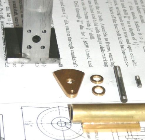 Best regards Terry |
| Ian S C | 21/12/2010 13:34:26 |
7468 forum posts 230 photos | Just checking the firures, and I see the the numbers for g loading has been bought down from the American test figs to +3.56 and -i.42, the cocpit section was tested on the first airframe to 40g. We still seem to have a thriveing aircraft industry in NZ, one vertion of the Cresco a light transport, used for parachute jumping. Another a light military reconnaisance aircraft. Ian S C |
| Terryd | 21/12/2010 14:08:39 |
1946 forum posts 179 photos | Hi Ian, We've come a long way from Medieval clockmaking  Terry |
| RJW | 21/12/2010 14:56:08 |
| 343 forum posts 36 photos | Ian, do you think the G loading was reduced because the certification bods got wind of all the patches and rivets ramping up the AUW beyond load limits <LOL> Sorry couldn't resist, but Wow, 8g's limit on an airframe loaded with nasty chemicals is awsome even if few pilots around could sustain those figures and stay conscious, but stitched up with alloy plasters too makes the mind boggle. I'm always amazed that wings don't get more frequently torn off crop sprayers .... or perhaps it's just that we just don't hear about it! When you think about it, metal fatigue rears its ugly head in just about everything we do at some point! Terry, Nice joint! I have quite a few of Wilding's books, but not for that particular clock, so I was mainly using my imagination to visualise the joints, and dovetailing would certainly add mechanical strength to the frame. I'll have to have a rummage through some of my clock books to see if any photo's illustrate just what types of jointing methods were used back then. I must confess to not being too interested in iron frame and lantern clocks, they're a bit too 'agricultural' for my taste, and probably why I never bought that particular book. Although the majority of my clock experience has been repairing or making replacement bits for what was already there, I do have a few skeleton clocks I'm making and slowly getting my teeth into, but they're all brass frames with pillars. I may get around to posting some pic's up at some point. I'm sorry to hear about you losing your models that way, all that graft and attention to detail going up in smoke must have been a soul destroying experience! Regards John |
| Ian S C | 22/12/2010 02:43:07 |
7468 forum posts 230 photos | No John, I think they are being a bit more honest, the company that did the design and initial build was trying to sell the FU25 light ground attack aircraft to anyone who would buy it, it was a similar design, and a Japanese co bought that and built some. So they were trying to impress. I think the only fatigue problem with the Fletcher is with the fin attachment, the problem has shown up as the hp has increased from 225hp to 750hp. I think it has caused one crash. Structual failure may have caused some crashes, but regular inspection seems to cover most problem areas. Ian S C
PS We'd better quit while the goings good or we'll get grounded! |
| Terryd | 22/12/2010 04:37:36 |
1946 forum posts 179 photos | Hi Guys, Several threads seem to end up as 'aeroplane' threads, would it not be a good idea to start a thread based on this theme for those interested and those of us who aren't too bothered could ignore it. Seasons greetings Terry |
| RJW | 22/12/2010 10:35:22 |
| 343 forum posts 36 photos | Hi Ian, a very off topic reply; we're already grounded, been stuck under a foot of snow for a month, anyway, will probably see you in the new 'Aviation related' topic that someone has kindly started! John |
| Gordon W | 22/12/2010 17:31:56 |
| 2011 forum posts | I don't know what metal fatigue has to do with the original question. Wasn't it about bending a bit of black bar ? Drilling a hole at end of a crack is a standard technique, good enough for cracked cylinder blocks, cracks in chassis etc. etc. If welding a crack in thinnish stuff, start at crack end ,this closes the crack and stops it spreading, probably not used on machines carrying lots of people, esp. above ground. |
| Clive Cassel | 23/12/2010 09:57:09 |
| 5 forum posts | Dear All
Many thanks for your responses. For my next attempt I shall partly saw through bar then heat to red and then bend. If that fails I shall dovetail cut and join.
Cheers
Clive Cassel
|
Please login to post a reply.
Magazine Locator
Want the latest issue of Model Engineer or Model Engineers' Workshop? Use our magazine locator links to find your nearest stockist!
Sign up to our Newsletter
Sign up to our newsletter and get a free digital issue.
You can unsubscribe at anytime. View our privacy policy at www.mortons.co.uk/privacy
Latest Forum Posts
- hemingway ball turner
04/07/2025 14:40:26 - *Oct 2023: FORUM MIGRATION TIMELINE*
05/10/2023 07:57:11 - Making ER11 collet chuck
05/10/2023 07:56:24 - What did you do today? 2023
05/10/2023 07:25:01 - Orrery
05/10/2023 06:00:41 - Wera hand-tools
05/10/2023 05:47:07 - New member
05/10/2023 04:40:11 - Problems with external pot on at1 vfd
05/10/2023 00:06:32 - Drain plug
04/10/2023 23:36:17 - digi phase converter for 10 machines.....
04/10/2023 23:13:48 - More Latest Posts...
- View All Topics
Support Our Partners


Shopping Partners
Subscription Offer

Latest "For Sale" Ads
- Reeves** - Rebuilt Royal Scot by Martin Evans
by John Broughton
£300.00 - BRITANNIA 5" GAUGE James Perrier
by Jon Seabright 1
£2,500.00 - Drill Grinder - for restoration
by Nigel Graham 2
£0.00 - WARCO WM18 MILLING MACHINE
by Alex Chudley
£1,200.00 - MYFORD SUPER 7 LATHE
by Alex Chudley
£2,000.00 - More "For Sale" Ads...
Latest "Wanted" Ads
- D1-3 backplate
by Michael Horley
Price Not Specified - fixed steady for a Colchester bantam mark1 800
by George Jervis
Price Not Specified - lbsc pansy
by JACK SIDEBOTHAM
Price Not Specified - Pratt Burnerd multifit chuck key.
by Tim Riome
Price Not Specified - BANDSAW BLADE WELDER
by HUGH
Price Not Specified - More "Wanted" Ads...
Get In Touch!
Do you want to contact the Model Engineer and Model Engineers' Workshop team?
You can contact us by phone, mail or email about the magazines including becoming a contributor, submitting reader's letters or making queries about articles. You can also get in touch about this website, advertising or other general issues.
Click THIS LINK for full contact details.
For subscription issues please see THIS LINK.
Digital Back Issues


Donate

 Register
 Log-in
Model Engineer Magazine
- Percival Marshall
- M.E. History
- LittleLEC
- M.E. Clock

ME Workshop
- An Adcock
- & Shipley
- Horizontal
- Mill

Subscribe Now
- Great savings
- Delivered to your door

Pre-order your copy!
- Delivered to your doorstep!
- Free UK delivery!
All Forum Topics > Beginners questions > Metal fatigue and clock making