Forum sponsored by:

Disassembling of Minimill / X2-clone / XJ-12 Ballbearings
Stripping down Chinamill
| Peter G. Shaw | 05/06/2010 21:54:45 |
 1531 forum posts 44 photos | John, The link doesn't work for me. Can you help? Peter G. Shaw |
| John Shepherd | 06/06/2010 09:46:02 |
| 222 forum posts 7 photos | Not sure what has happened as it obviously has worked and I tested it after posting but it does not work now so here is the link again.
If that dosent work it can be found as file 'Seig X2 X axis Alignment Aid' in:
John
Tested and working now.
Edited By John Shepherd 1 on 06/06/2010 10:05:05 Edited By Kelvin Barber on 07/06/2010 14:34:56 |
| Peter G. Shaw | 06/06/2010 22:00:41 |
1531 forum posts 44 photos | Still doesn't work, and the yahoo reference wants me to join a group. So I give up. Many thanks, John anyway. Regards, Peter G. Shaw |
| Versaboss | 06/06/2010 22:36:37 |
| 512 forum posts 77 photos | Thanks Peter, so it seems I am not alone. Hmm, wonder if I did something wrong, but I seem to remember that late in last night I wrote a plea to use Tinyurl instead of such long and error-prone URLs. Possibly that posting ended in the big bit-bucket somewhere.... Greetings, Hansrudolf |
| Roberto dasso | 07/06/2010 07:52:01 |
| 8 forum posts | Yes..for downloading that file, it is required to join the group.. |
| John Shepherd | 07/06/2010 08:17:12 |
| 222 forum posts 7 photos | Ok Lets try this way. (For some reason it would appear that Yahoo URLs change frequently.)
 There have been many posts and articles about the need to align the carriage and spindle housing on the X2 or its variants. The following does not repeat the methods that may be used to measure and correct the alignment but shows a simple modification that will take some of the hit and miss out of the adjustment. Basically the modification is a bar bolted to the motor mounting plate with two adjusting screws with lock nuts that “rock” the casting into alignment. I hope the picture shows the principle and I will not give dimensions as they are not critical. I did originally consider just drilling and tapping two holes in the mounting plate for the adjusting screws but having looked at the under side, its shape does not lend itself to this so the bar was added as an extension. The only modification to the machine is two 6mm tapped holes in the end of the motor mounting plate to attach the bar. The photograph shows the prototype – At some stage I will probably replace the adjusting screws with socket screws. I may also consider putting two locating dowels in the bar/motor mounting plate. In use the head is lifted nearly off the column so that the four bolts holding the carriage and spindle housing together are slackened slightly. I then used Rolies Dads Method (RDM) that is well described elseware to achieve alignment. The two adjusting screws are initially set to just touch the carriage casting and one of them adjusted to correct the error. I found that very fine adjustment can be achieved without having the four bolts too loose. This and the bar itself means that there is less chance of movement when everything is tightened up. Leaving the bar in place will also help to prevent future movement and provide a reference if you have to dismantle. Edited By John Shepherd 1 on 07/06/2010 08:20:37 |
| Roberto dasso | 08/06/2010 21:10:53 |
| 8 forum posts | Ok.. i got the mini-mill today..
It is not bad, it seems a good little machine I measured the spindle runout (outside): less than 0.01 mm.. the report included says 0.01 at the end of the spindle and 0.02 100 mm to the end of the splinde Anyone has checked the spindle runout of this kind of milling machine? About the dials.. on the cross table are graduated 0.02 mm.. 75 x revolution total 1.5 mm/rev (0.02*75) 75 of course is the number of the minor graduations, not 0.75 mm /rev the vertical fine feed.. 0.025 x 60 ..again 1.5 mm/rev |
| Peter G. Shaw | 09/06/2010 12:48:52 |
1531 forum posts 44 photos | Hi Roberto, Agree with the dials, but still difficult to use. I have a conversion table on my mill giving the number of divisions for varying amounts of travel, eg say 1mm and 0.25 mm. So if I want 1.25mm, I add the two numbers together. Job done. Haven't checked spindle run out. Regards, Peter G. Shaw |
| John Rudd | 09/06/2010 12:49:01 |
| 1479 forum posts 1 photos | Marcus,
I changed the bearing out on my X2 clone (Chester Conquest) when I moved over to a belt drive conversion...Taper rollers from a local bearing supplier (SKF brand).
I didnt bother with the smaller bearings as I didnt replace the countershaft.
My mill is much quieter post conversion. |
| Roberto dasso | 09/06/2010 14:18:26 |
| 8 forum posts | Posted by Peter G. Shaw on 09/06/2010 12:48:52: Hi Roberto, Agree with the dials, but still difficult to use. I have a conversion table on my mill giving the number of divisions for varying amounts of travel, eg say 1mm and 0.25 mm. So if I want 1.25mm, I add the two numbers together. Job done. Haven't checked spindle run out. Regards, Peter G. Shaw Hello Peter it is a very good idea.. i will do the same, your table is very helpful ! Thanks Regards Roby |
| Peter G. Shaw | 09/06/2010 20:37:26 |
1531 forum posts 44 photos | Hi Roberto, Does this help? 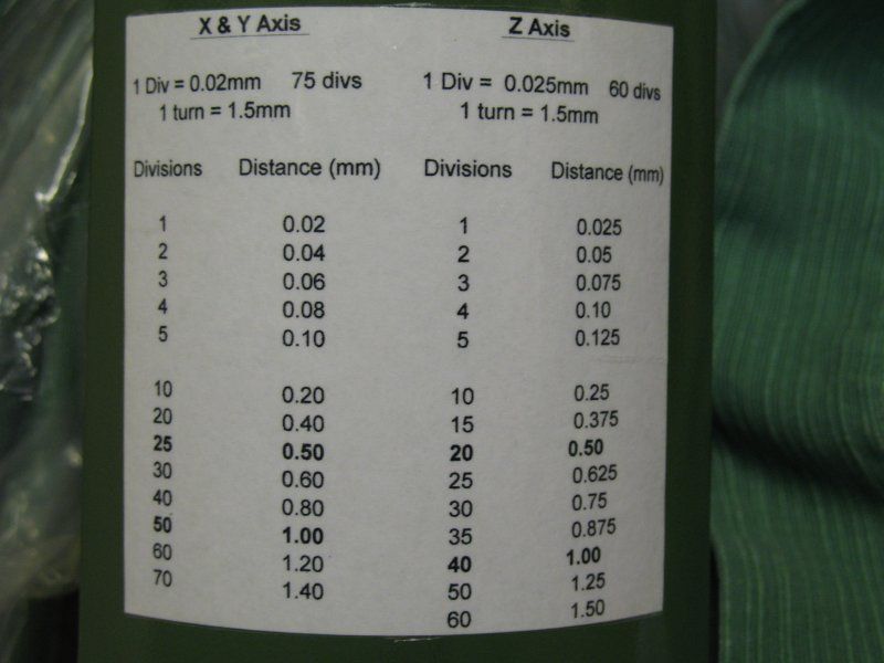 I mounted mine on the front of the motor casing. Regards, Peter G. Shaw |
| Roberto dasso | 09/06/2010 21:03:55 |
| 8 forum posts | Hi Peter Yes.. it helps a lot!!!! ehehe Thank you very much Regards Roberto Edited By Roberto dasso on 09/06/2010 21:04:19 |
| pfav | 11/06/2010 10:56:06 |
| 3 forum posts | Hi all, I just subscribe the forum, and I am a novice. I start metalworking in support to my interest on Kite. 2 years ago, I bought a mini lathe (C3 like) and after one years a minimill. I bought a 2nd hand minimill that is the same model as warco. Using slitting saw I broken spindle gear. I start replace the gears and I'm thinking to use metal gears on spindle and plastic on coutershaft. After remove the spindle i found a problem: bottom bearing is damaged (may by some metal or plastic garbage) I try to find a replacement and for an SKF 7206 AC I have to pay Euro 150.00!!! Now some considerations: the bearing position require a sealed version, but the 72xx model doesn't have sealed version. The tapered version, more cheap, has the same problem. There is not space to use sealing ring. Considering the overall machine precision, the SKF expert suggested me to use 2 6206 2ZR. The axial load is around 200Kg and a skf ball bearing is more precise of a Chinese 7206! What do you thinks ? regards Paolo |
| Clive Farrar | 13/06/2010 21:06:23 |
 125 forum posts 41 photos | Well chaps I have just started to convert mine to belt drive.
I have the drawings and info from John Rudd I will need some carefull thought to mod these to suit my WARCO due to the spped controller box location.
I have stripped it all down today and after extracting the small gear that had broken into about 20 bits and removed 4 teath from the other gear.
The first job was to replace the bearings with taper rollers.
My bottom ball bearing also fell apart when removing the shaft from the head. The inner race was a VERY tight fit on the shaft. If I did not have a No3 broach press I would not have got it apart.
They have been replaced with Nachi H-E30206J bearings from ARC Eurotrade. These are exactly the same as those used in the mini lathe, as mentioned above.
I also needed the press to get them back on. Fitting these has reduced the length of shaft above the bearing by approx 4 mm.
As I have no intention of using gears ever again I have removed the layshaft from the head.
I have left the small bearing in the head and blanked the centres with grommets.
I know the tapers are open at the bottom but so are the ball bearings and the metal fling washer and plastic collar over the bearing obviously do their job as there was NO contamination in the old ball race.
If only the rest of the mod would go as easily.
Regards Clive |
| pfav | 14/06/2010 21:45:24 |
| 3 forum posts | Thanks Clive, agree to use tapered bearing if you remove Gears from head. I'd like to use gears for a while, so I'm worried about contamination. (let me prepare my own belt conversion Kit  ) )Have someone used a couple of 6206ZZ for upper and bottom sides ? Is the precision worst? regards Paolo |
| Stub Mandrel | 16/06/2010 21:11:04 |
 4318 forum posts 291 photos 1 articles | It was only recently it ocurred to me that replacing those stupid 75 division index wheels with 60 division ones would give me 0.025mm/division which is close enough to a thou for my agricultural approach. Also 10 divisions = 0.25mm, 40=1mm and I can ignore that discontinuity at 75 divisions. Best of all, its the same as my lathe then, so only one set of thought processes needed! I plan to modify teh existing or make new dials soon. Neil |
| Roberto dasso | 18/06/2010 10:07:24 |
| 8 forum posts | Yesterday I have checked the run out of the stock spindle and bearings This is the video It seems very good (the dial indicator is metric 0.01 mm). The accuracy report of the machine says 0.01 mm at the end of the spindle, and 0.02 mm 100 mm to the end of the spindle. |
| Clive Farrar | 21/06/2010 21:54:19 |
125 forum posts 41 photos | Mine is a WARCO mini mill and the switch box gets in the way of both mode I have seen and leaves no space to dog leg round the back of it.
After a bit of measuring and ponderingI worked out that I could move it down so the top was level with the head thus giving me space fot the T shaped mounting plate.
The draw back is that it is now below the bottom of the head. The just acceptable news is that that bottom edge is level with the morse taper mouse.
that should not be a problem for me as I nearly allways use an ER32 collet chuck which drops the cutter some 50 mm + below that point.
Now to start on the metal.
Regards Clive |
| Stub Mandrel | 21/06/2010 22:27:49 |
4318 forum posts 291 photos 1 articles | > morse taper mouse It's good to know that we can obtain pets that are compatible with our tools. A friend spent ages trying to get hold of a Browne and Sharpe gerbil. Neil |
| MarcuSweden | 04/07/2010 22:59:29 |
 29 forum posts 20 photos | " On both my mill, and my friends mill, the fine feed did not work. The manual did not even mention it, and it wasn't until I downloaded a document from the Little Machine Shop in America that I found out how to make it work. What my friend and I discovered is that there is a gross misalignment between the the support block and the bracket adjacent to the fine feed knob such that the support block requires shimming out along its front edge (as you look at it from the front). Furthermore, the support block housing is too short for the actual worm itself, causing binding of the worm inside the block. This is cured by, in my case, adding washers between the end cover plate and the support block thus giving clearance for the worm to rotate. In addition, my friend discovered that his was seized up due to gunge." Peter : Can You please explain a little bit more about the "support block and the bracket adjacent" and also "the support block housing" , my problem here is that i acctually dont understand thoose english words, but i have the schematic with all parts numbered so i can easily see what part that is discussed. 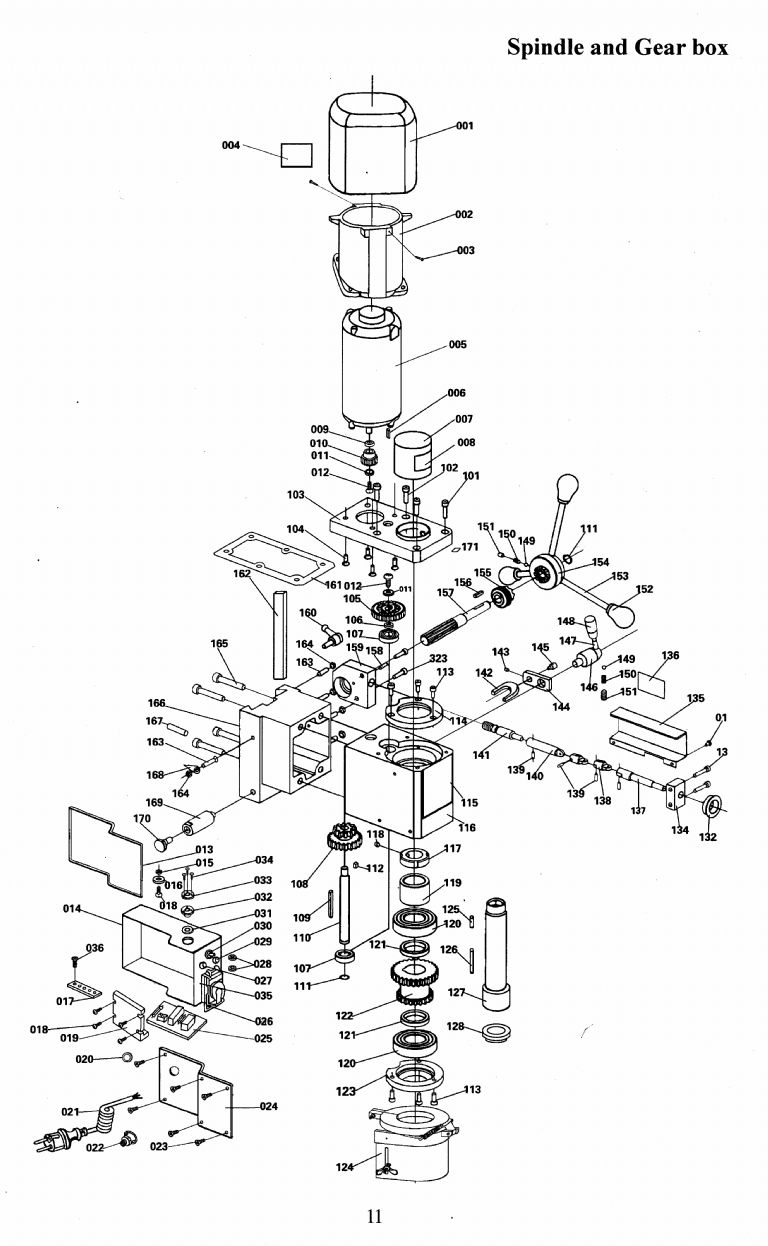 click to enlarge. Edited By MarcuSweden on 04/07/2010 23:06:34 |
Please login to post a reply.
Magazine Locator
Want the latest issue of Model Engineer or Model Engineers' Workshop? Use our magazine locator links to find your nearest stockist!
Sign up to our Newsletter
Sign up to our newsletter and get a free digital issue.
You can unsubscribe at anytime. View our privacy policy at www.mortons.co.uk/privacy
Latest Forum Posts
- hemingway ball turner
04/07/2025 14:40:26 - *Oct 2023: FORUM MIGRATION TIMELINE*
05/10/2023 07:57:11 - Making ER11 collet chuck
05/10/2023 07:56:24 - What did you do today? 2023
05/10/2023 07:25:01 - Orrery
05/10/2023 06:00:41 - Wera hand-tools
05/10/2023 05:47:07 - New member
05/10/2023 04:40:11 - Problems with external pot on at1 vfd
05/10/2023 00:06:32 - Drain plug
04/10/2023 23:36:17 - digi phase converter for 10 machines.....
04/10/2023 23:13:48 - More Latest Posts...
- View All Topics
Support Our Partners


Shopping Partners
Subscription Offer

Latest "For Sale" Ads
- Reeves** - Rebuilt Royal Scot by Martin Evans
by John Broughton
£300.00 - BRITANNIA 5" GAUGE James Perrier
by Jon Seabright 1
£2,500.00 - Drill Grinder - for restoration
by Nigel Graham 2
£0.00 - WARCO WM18 MILLING MACHINE
by Alex Chudley
£1,200.00 - MYFORD SUPER 7 LATHE
by Alex Chudley
£2,000.00 - More "For Sale" Ads...
Latest "Wanted" Ads
- D1-3 backplate
by Michael Horley
Price Not Specified - fixed steady for a Colchester bantam mark1 800
by George Jervis
Price Not Specified - lbsc pansy
by JACK SIDEBOTHAM
Price Not Specified - Pratt Burnerd multifit chuck key.
by Tim Riome
Price Not Specified - BANDSAW BLADE WELDER
by HUGH
Price Not Specified - More "Wanted" Ads...
Get In Touch!
Do you want to contact the Model Engineer and Model Engineers' Workshop team?
You can contact us by phone, mail or email about the magazines including becoming a contributor, submitting reader's letters or making queries about articles. You can also get in touch about this website, advertising or other general issues.
Click THIS LINK for full contact details.
For subscription issues please see THIS LINK.
Digital Back Issues


Donate

 Register
 Log-in
Model Engineer Magazine
- Percival Marshall
- M.E. History
- LittleLEC
- M.E. Clock

ME Workshop
- An Adcock
- & Shipley
- Horizontal
- Mill

Subscribe Now
- Great savings
- Delivered to your door

Pre-order your copy!
- Delivered to your doorstep!
- Free UK delivery!
All Forum Topics > Workshop Tools and Tooling > Disassembling of Minimill / X2-clone / XJ-12 Ballbearings