Forum sponsored by:

Rina and T&K drawings
| John Olsen | 28/10/2010 19:49:27 |
| 1294 forum posts 108 photos 1 articles | Hi James, OK, I have had a quick look and there are now two more drawings showing a possible mod for the cylinder head rocker post. The rocker also needs a mod to suit this. What we do is make the post a bit bigger, with a bigger slot in the top, so we can screw it down with a screw through the middle. I have assumed a screw with a 3/16 inch head. I think I have shown the hole 6BA tapping size, it should of course be clearance, and would be tapped into the head, not right through into the cylinder. To allow for the wider slot in the top of the valve rocker, I have put two bosses on each side of the rocker, this would also give a better bearing surface here. When I get home later I will refine these a bit, and see how it looks in the assembly. Time to do these drawings was half an hour. Note they need a little tidying up still, I see one of the dimensions is on the actual part, which is not good practice. regards John  |
| John Olsen | 29/10/2010 04:03:02 |
| 1294 forum posts 108 photos 1 articles | 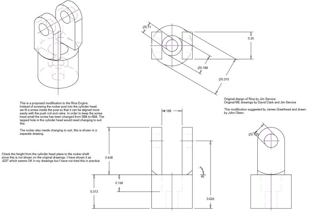 OK, I have been out, come back, and edited things a bit more. I have changed the hole in my post to suit a 6 BA screw, this would also require changing the tapped hole in the cylinder head to suit 6 BA. Actually my own choice would probably be a small cap screw, I have these in 2.6mm or 3mm. The latter might need the head reducing in diameter a whisker to fit. Although the cap head might be an anachronism for this type of engine, it would hardly show, being under the rocker. I have replaced the drawings in my album with the updated ones, and have included acknowlegement of the original designer (Jim Service) in them, along with some notes. The intention of this modification is to make it easier to align the rocker with the pushrod and valve. Instead of screwing the post itself into a tapped hole in the head, we fit a small screw down the middle of the post. To allow enough room for the screw head, the slot has to be a little wider, and this requires adding bosses to the rocker. I think this still ends up looking in keeping with the style of the engine. Please note that this modification has not been tested, and in particular the height from the cylinder head plane to the rocker shaft was not given in the original drawings. So please check this on the job before making this part. A similar modification may be done to the pivot for the governor latchout lever by bringing a small screw through from the inside of the frame. regards John Edited By John Olsen on 29/10/2010 04:10:00 |
| Jim Greethead | 29/10/2010 06:20:15 |
 131 forum posts 8 photos | Your solution is much better than mine John, simpler and more elegant. Thanks.
I note that you have omitted the fuel tank arrangements and the muffler which were also omitted from the original drawings. I wonder if Jim Service could be persuaded to offer some suggestions for these items.
Jim
|
| John Olsen | 29/10/2010 06:59:33 |
| 1294 forum posts 108 photos 1 articles | Hi James, There are a few other parts missing too. I had to infer a length for the rocker post because it was not in the drawings, neither was the length of the valves. We also don't have specifications for the valve springs, colletts and retainers. There is a little grooved spool for the governor that is not in the drawings too. Most of these would not be a show stopper, there is enough there to determine what they should be like, but it would be easier for beginners if they were all covered. I think the fuel is intended to be butane, so it will come in a ready to use tank, and the regulator was discussed. I hope I don't sound too niggly above, I am well aware from my own experience with simpler construction articles how difficult it is to make sure that you have included all the information that will be needed. I actually got started on the CAD model because David Clark included the example pencil drawing above...it seemed like a good exercise to try to do a drawing off it myself and then compare to the magazine one. My interpretation of that part actually came out a little different to Davids. So having done that I thought I would do a few more, and one thing lead to another. I am actually finding that it is a good idea to make a 3D model from any set of drawings before machining parts, for one thing it helps to see how it all goes together, and for another it helps sort out any mistakes in the original drawings. regards John |
| Jeff Dayman | 31/10/2010 13:38:23 |
| 2356 forum posts 47 photos | The Rina carburetor drawings are some of the most unclear I've ever seen. A section through the body vertically would help immensely. I think there will be a lot of scrap carbs and stopped projects because of those awful drawings. On the carb valve spring, no hints at all are given about appropriate dia, wire dia, or pitch. The text just says "light spring".
In addition the ignition lever drawing in the same article is pretty much unintelligible and has at least one line (a horizontal one, at the step) that should not be there. I could make the assy from the photo but certainly not from the drawing.
JD |
| John Olsen | 31/10/2010 21:00:56 |
| 1294 forum posts 108 photos 1 articles | HI Jeff, Well here is my interpretation of how it should go together. Note that I am not the original designer and I have never built one of these, so it could be wrong. It is just my interpretation from what was in the magazine. I haven't attempted to show the carb spring, or the main valve springs or governor springs for that matter. They are not that hard to draw, but I would like to get the size and number of turns something like right. I'm presuming that the way it works is that the valve drops down and cuts off the gas supply when the engine stops sucking air. So the regulator must be supplying gas at quite a low pressure. If the pressure is too high, valve will need too much spring pressure and the engine will have trouble sucking in enough mixture to do any good. Any experts, feel free to correct me on this, I've played with a "LIttle Jumbo" running on petrol, but have never played with a small one running on butane. The advantage of redrawing things in a 3D CAD program is that it helps you get a clear picture of how things actually go together, and sometimes helps explain what some of the features are actually for. regards John 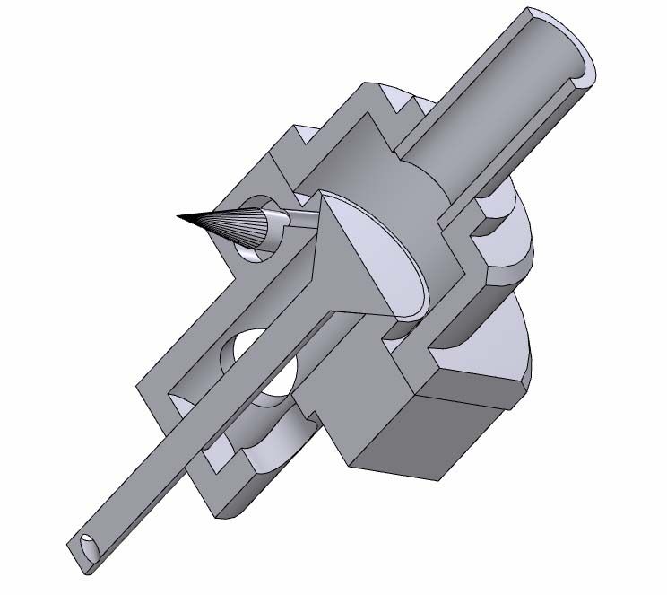 |
| David Clark 1 | 31/10/2010 21:04:36 |
 3357 forum posts 112 photos 10 articles | Hi There
I disagree that the drawing is unclear.
Both drawings look fine to me.
Yes, the line may be unecessary for the ignition drawing but it is in the photo so could be to do with setting up.
It was on the original drawing so was left.
I did not have information on the spring but it is shown in the photo and it can be seen it is a light spring.
regards David
|
| David Clark 1 | 31/10/2010 21:06:32 |
3357 forum posts 112 photos 10 articles | Hi John
We don't have time to redraw in a cad package.
All we can do is tidy up where necessary.
I do correct errors when I see them but short of building every model we publish we will occaisonally get errors.
regards David |
| Jim Greethead | 31/10/2010 21:45:31 |
131 forum posts 8 photos | No John, I don' t think you sound too niggly. I agree that we can probably sort out the missing bits, given time, but some advice would be helpful.
As a newcomer to IC engines, I am very grateful to Jim Service for the effort he has put in to this project; without people like him, I would be unable to get started. And without people like you, I would probably be unable to finish.
Your drawing of the carburettor is superb! I must confess that I have not had a close look at it but there are features in your drawing that I had not noticed.
You mentioned that details of the inlet valve are missing. Other people to whom I have spoken have mentioned difficulty (with other engines) in getting the spring tension just right. This has led me to speculate about some spring tension adjustment: maybe a threaded collar or similar. What to you think?
Jim
|
| John Olsen | 31/10/2010 22:34:25 |
| 1294 forum posts 108 photos 1 articles | Hi David, If you can get the necessary details from Jim Service I can update my drawings with them. Having done my drawings mainly as a learning exercise, it would seem a pity not to make some use of them. As I have mentioned elsewhere, one possibility would be to put the Adobe PDF of the 3D model up on the website. This would allow people to view it from different angles, and also to remove parts and see the internal details. (At the moment they would see that I have not bothered to draw in the gudgeon pin or the rings!) The Isometric views of the more complex parts are also possibly a help for people to visualise what they are going to make Details I would like to clarify are the overall length of the valves, the details of the collets and spring retainers, and the details of all the springs including the governor springs. (Wire gauge, diameter, number of turns and free length) The gudgeon pin is no problem, although I would like to know if the intention was to make it hollow or not. It is retained by a screw in the piston, so presumably doesn't need end pads. The rocker post height may need to vary depending how long the valves are supposed to be, but I can change that in my drawings very easily, either for the original post or for my suggested variation. The little collar for the governor is also not too much of a problem. A sketch of the fitting in the exhaust might help too...We don't want to put to much back pressure on. I suspect that it will probably not be too loud when running, even with a minimal muffler. regards John |
| David Clark 1 | 01/11/2010 10:14:09 |
3357 forum posts 112 photos 10 articles | Hi John
Jim is not on email so I will have to phone him or write to him.
Not sure if I have his phone number.
regards david
|
| John Olsen | 01/11/2010 19:11:05 |
| 1294 forum posts 108 photos 1 articles | Hi David, I have heard from Jim directly so I now have the details, I will do some drawings later today. regards John |
| John Olsen | 02/11/2010 04:51:01 |
| 1294 forum posts 108 photos 1 articles | Hi All, As mentioned above, Jim Service has provided me with some dimensions for the governor sleeve, the rocker post, and the valves. I have modified my drawings, but would suggest sanity checking all this before going ahead too far. I have not made any of these parts, other than in a 3D modeling program. I found the E circlip for the valves in a catalogue, and it is intended for use with 1/8 inch shaft. If you use a different one, say a metric one be prepared to adjust the groove to suit. There are three new drawings, which can be found in my album, I will just link to the governor one here to avoid filling the page up too much. I have not modified the height of the alternative design of rocker post yet, if you decide to make that one increase the height to be the same as the original one, eg 13/16" long. Jim Service had no problem getting the original one to line up nicely, so either way should be fine. regards John 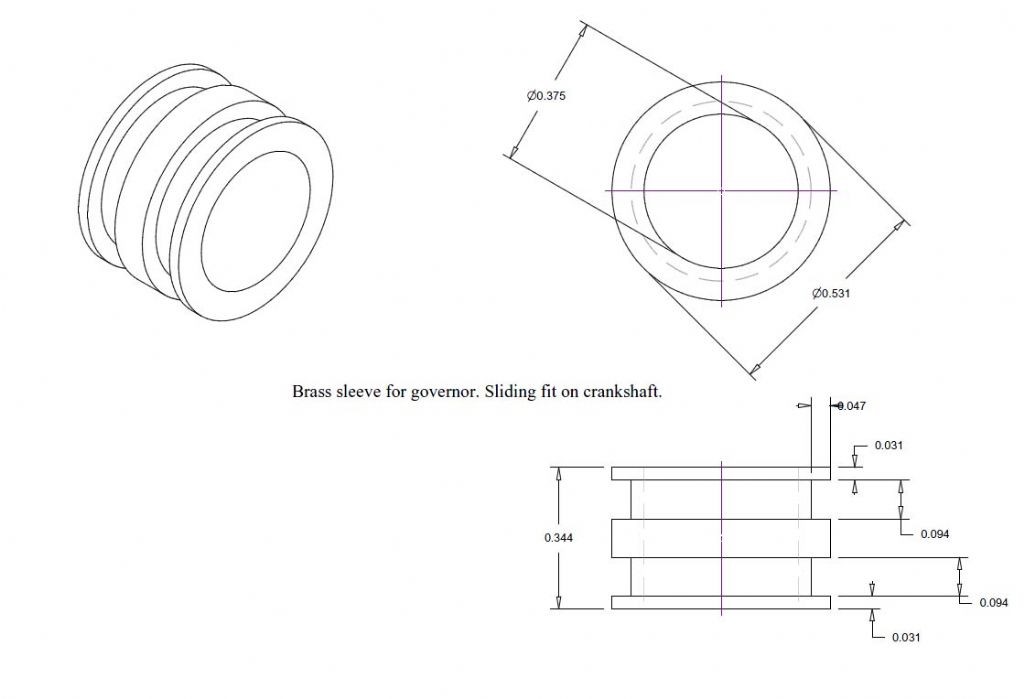 |
| Ian S C | 02/11/2010 09:19:07 |
 7468 forum posts 230 photos | John, re the ignition lever; the horizontal line should be there, if you look closely at the photo the vertical part has a step there, but the edge veiw shows no thickness dimentions. Ian S C |
| David Clark 1 | 02/11/2010 11:14:32 |
3357 forum posts 112 photos 10 articles | Hi There
It looked like marking out to me but I left the line in as it might be useful for setting up.
regards David
|
| Jim Greethead | 02/11/2010 12:14:54 |
131 forum posts 8 photos |
I understand why Jim would make the conversion shown in Fig 8 if the machine was already constructed but I can't help thinking that there might be a better way to incorporate the CDI system than by modifying the ignition lever.
Since we no longer need the lever to adjust the timing, a more unobtrusive arrangement should be possible. I will give it some thought; anyone else have ideas?
Jim
|
| Ian S C | 02/11/2010 13:11:15 |
7468 forum posts 230 photos | David, i used a manifying glass on the photo, there is a step where the line is, and a line continues round the circular part. The 1/8" hole marked on the drawing is not in the same place as the photo. The two items are quite different. Ian S C |
| John Olsen | 02/11/2010 22:38:43 |
| 1294 forum posts 108 photos 1 articles | Hi All, Jim Service has kindly taken the head off his engine so that he could measure the springs for us. Note that these were springs from his collection of bits that might be useful someday, so you may not be able to match them exactly. But this should give a good starting point for experiment. From Jim: >== Exhaust valve is 5/8 " long and the outside diameter is 0.278". The gauge is 22 SWG or 0.028" and there are 8 turns. Inlet valve is 11/16 " long but has been stretched somewhat and the outside diameter is 0.278". The gauge is 22 SWG or 0.0148". There are 6 turns. Carb is 5/16" long and the outside diameter is 0.12". The gauge is 35 SWG or 0.0084" and there are 6 turns. ==< regards John |
| Graham Bird | 08/11/2010 21:55:21 |
| 5 forum posts | Hi All
Can anyone please advise recommended spark plug for Rina hit and miss engine?
Regards
Graham |
| MichaelR | 09/11/2010 08:06:15 |
 528 forum posts 79 photos | NGK CM- 6 10mm should be OK, seehere |
Please login to post a reply.
Magazine Locator
Want the latest issue of Model Engineer or Model Engineers' Workshop? Use our magazine locator links to find your nearest stockist!
Sign up to our Newsletter
Sign up to our newsletter and get a free digital issue.
You can unsubscribe at anytime. View our privacy policy at www.mortons.co.uk/privacy
Latest Forum Posts
- hemingway ball turner
04/07/2025 14:40:26 - *Oct 2023: FORUM MIGRATION TIMELINE*
05/10/2023 07:57:11 - Making ER11 collet chuck
05/10/2023 07:56:24 - What did you do today? 2023
05/10/2023 07:25:01 - Orrery
05/10/2023 06:00:41 - Wera hand-tools
05/10/2023 05:47:07 - New member
05/10/2023 04:40:11 - Problems with external pot on at1 vfd
05/10/2023 00:06:32 - Drain plug
04/10/2023 23:36:17 - digi phase converter for 10 machines.....
04/10/2023 23:13:48 - More Latest Posts...
- View All Topics
Support Our Partners


Shopping Partners
Subscription Offer

Latest "For Sale" Ads
- Reeves** - Rebuilt Royal Scot by Martin Evans
by John Broughton
£300.00 - BRITANNIA 5" GAUGE James Perrier
by Jon Seabright 1
£2,500.00 - Drill Grinder - for restoration
by Nigel Graham 2
£0.00 - WARCO WM18 MILLING MACHINE
by Alex Chudley
£1,200.00 - MYFORD SUPER 7 LATHE
by Alex Chudley
£2,000.00 - More "For Sale" Ads...
Latest "Wanted" Ads
- D1-3 backplate
by Michael Horley
Price Not Specified - fixed steady for a Colchester bantam mark1 800
by George Jervis
Price Not Specified - lbsc pansy
by JACK SIDEBOTHAM
Price Not Specified - Pratt Burnerd multifit chuck key.
by Tim Riome
Price Not Specified - BANDSAW BLADE WELDER
by HUGH
Price Not Specified - More "Wanted" Ads...
Get In Touch!
Do you want to contact the Model Engineer and Model Engineers' Workshop team?
You can contact us by phone, mail or email about the magazines including becoming a contributor, submitting reader's letters or making queries about articles. You can also get in touch about this website, advertising or other general issues.
Click THIS LINK for full contact details.
For subscription issues please see THIS LINK.
Digital Back Issues


Donate

 Register
 Log-in
Model Engineer Magazine
- Percival Marshall
- M.E. History
- LittleLEC
- M.E. Clock

ME Workshop
- An Adcock
- & Shipley
- Horizontal
- Mill

Subscribe Now
- Great savings
- Delivered to your door

Pre-order your copy!
- Delivered to your doorstep!
- Free UK delivery!
All Forum Topics > Drawing Errors and Corrections > Rina and T&K drawings