Forum sponsored by:

Three Cylinder Steam Aero Engine
| Howard Lewis | 01/01/2021 09:17:27 |
| 7227 forum posts 21 photos | Excellent work, and good progress! Howard |
| John Purdy | 09/01/2021 06:38:55 |
 431 forum posts 252 photos |
After ensuring that the crank rotated freely in the front and rear bearings and the end float was good the cover was transferred to the mill, still in the chuck, and the DRO PCD function was used to drill the six #36 tapping holes for the 6-32 screws that fasten it to the front crankcase. The holes were then transferred to the front crankcase and tapped for the screws.
Edited By John Purdy on 09/01/2021 06:43:53 |
| John Purdy | 09/01/2021 07:49:57 |
431 forum posts 252 photos |
Boring out the webs for the crank pins (.503) and the crankshaft (.628). The ends of the .625" crank pin will be turned down to .500". The holes were bored .003 over size to allow clearance for the retaining compound which according to the specs is in the middle of the recommended clearance for maximum strength.
Cutting the key way .070" deep in the crank for the prop hub drive key with a #504 woodruff key seat cutter, having taken great pains to ensure that the shaft was parallel to the mill table in both the vert. and horiz. planes. It paid off as the hub slid on over the key with no problems and no shake.
The parts of the crankshaft ready to be fastened together with high strength retaining compound. There is still the large counterweights to be made, but at the moment I don't have any suitable material. They are 1.200" deep sectors of a 3.520" diameter circle, one being .850" thick and the other .700" thick, each fastened to the webs with two 10-32 hex socket cap screws.
After fastening the parts together and given 24 hours to cure, the crank was set up in the mill to drill and ream for the 5/32" cross pins.
The setup I used to drill and tap the 1/4-28 hole in the rear end of the crankshaft for the valve eccentric drive pin. I would have preferred to use the dividing head set vertically and the 3 jaw but there was insufficient head room on my mill. As it was with this setup there still was no head room to use my co-axial centre finder (a great piece of kit but it takes up about 6" of head room), hence the use of the dial gauge in the picture to centre it under the spindle. The mill PCD function on the DRO was used to position the hole for the eccentric pin at a radius of .275" and 60 degrees CCW from the crank pin.
Tapping the end of the crank for the eccentric pin after drilling #3 x 5/8" deep. The clamp across the collet and vice was put on as I thought that the offset drilling pressure might possibly move the collet block in the vice.
The completed crankshaft except for the two counter weights. The outer end of the eccentric pin still needs to be finished. The plans call for it to be threaded 1/4-28 for a nut and washer but I think I will tap it and retain the washer with a small hex socket cap screw. The length will have to wait till the eccentric (for lack of a better name) is made so as to set the end clearance. The "eccentric" is a "Y" shaped unit, as seen here, with the three valve rods attached, one fixed and the other two pivoted and is driven by the pin on the end of the crankshaft. I can see two possible ways of making it. One, out of the solid involving a lot of hack sawing and or milling, the other built up from a central piece and two thinner outer cheeks, still involving hack sawing and milling but maybe less so. Haven't decided which way to go yet.
|
| JasonB | 09/01/2021 08:01:36 |
 25215 forum posts 3105 photos 1 articles | Your making good progress. With manual machines I think I would tackle the eccentric by starting with a block that it can be got out and add the three main holes on the mill. Then hold in 4-jaw to turn the spigot and tap the hole. After turning teh spigot there won't be masses to come of so could all be milled if you don't fancy sawing. Get the rotary table out set up vertically and mount by central hole to do most of the external shape and the two .350" wide slots, pin hole sand oil hole can be done at this time. Then filing buttons or mounted on an arbor to round the ends over. |
| John Purdy | 09/01/2021 22:49:49 |
431 forum posts 252 photos | Jason Your method for making it out of the solid is about how I was envisioning doing it, but like the crank counter weights I don't have any material big enough (1 3/16 x 1 1/2 x 5/8) hence the idea of building it up. I do have some 3/16 and 5/16 plate. Where I live the closest metal supplier is about 270 odd Km away and their delivery charge is about 5 times the price of the material. |
| JasonB | 10/01/2021 07:00:56 |
25215 forum posts 3105 photos 1 articles | Have you any 2" round bar, it would come out of a slice of that. |
| Rik Shaw | 10/01/2021 11:39:35 |
 1494 forum posts 403 photos | John - I am quite sure I could rustle up some suitable bits for you FOC but even then I fear the postal charge to Canada would be uneconomical Another glimpse of a 9" tall seven cylinder radial steamer in my small collection here: and here: Thanks to MichaelG for the book recommendation. I purchased it at the time. Good work being done John – be nice to see it (flying?) when you have finished. Rik |
| John Purdy | 14/01/2021 18:27:07 |
431 forum posts 252 photos | Jason - I do have a piece of 2" round of uncertain parentage that I could use, hadn't thought of that. Rik - Thanks for the offer but as you say the shipping charges are prohibitive. I used to get a fair bit of stuff from the UK up until about 10 years ago but since then the shipping has increased to the point that is is now two to three times the cost of the goods. Don't think it will ever be flying, too small for a real aircraft and too big for a model! Besides which I'd have to design and make a flash steam boiler. John Edited By John Purdy on 14/01/2021 18:31:04 |
| Howard Lewis | 14/01/2021 20:14:45 |
| 7227 forum posts 21 photos | Nice workmanship! Keep up the good work Howard |
| John Purdy | 15/01/2021 23:58:16 |
431 forum posts 252 photos |
The straight shank of the valve rod ends were turned on the end of some 1/2" brass rod and tapped 12-28. Held in a 5C collet in a collet block in the mill, the flats were milled and the hole drilled and reamed, 3 at 3/16" for the valve wrist pins and 2 at 1/4" for the pins in the "eccentric". Returned to the lathe they were cut off slightly over length. The valve rods themselves are 7/32" dia. and are threaded 12-28 at each end. At this stage only one end is threaded as the final length will be determined when assembled.
Held in the ER collet chuck the heads were all skimmed to to a length of .431" and then, using the Radford/GHT spherical turning tool set to a radius of 3/4", the ends were radiused.
Next on the agenda are the connecting rods. The centre one is straight but the two outer ones are offset since the cylinders are all in the same plane. Holding the centre one for machining should be no problem, but the fact that the little end is considerably wider than the big end will complicate things. Not sure how I will go about it for the two offset ones. The centreline offset of these two works out to be .366" and as again the little end is wider than the big end the distance from the face of the big end to the little end on one side is .239"and the other .523.
|
| not done it yet | 16/01/2021 07:20:56 |
| 7517 forum posts 20 photos | .... the fact that the little end is considerably wider than the big end will complicate things ...... only to the extent of making some suitable spacers (thick shims🙂 |
| John Purdy | 16/01/2021 21:07:41 |
431 forum posts 252 photos | Yes I think there will have to be made some special shims (or gauge blocks?) and or jigs for the machining of the con rods. Have to sit down and have a good think how the best way to go is! |
| JasonB | 17/01/2021 07:02:45 |
25215 forum posts 3105 photos 1 articles | Have you got more than one vice? if do set them up side by side and for the offset ones pack one up to the offset amount. You can then face one side to correct offset and bore the holes in one setting then it's easy enough to flip it over and bring the ends to thickness. Even a tool makers clamp on the little end may do of you sit it on some packing and clamp the clamp down. |
| John Purdy | 18/01/2021 01:25:44 |
431 forum posts 252 photos | Jason I don't have two vices but I have used a tool makers clamp as you suggest in the past and is a definite possibility. I have cleaned up the width of the big ends, as they were tapered as cast, and at the same time adjusted them so the centre of the big end and the little end are in line. They can now be held securely in the vice horizontally to face them to set the thickness and offset, holding the little end with a tool makers clamp as you suggest. To drill for the big end bolts the only way I can see to do it at the moment is to hold then vertically clamped to an angle plate. |
| John Purdy | 24/01/2021 00:52:48 |
431 forum posts 252 photos |
Setup for finishing the big ends to thickness of .336" and skimming the face of the little end to clean up and be parallel to the big end. The amount off each side of the big end was adjusted so that centreline of the big and little end were coincident on the centre straight rod and the offset of .366" was maintained on the two outer offset rods. The setup in the picture was adjusted for the straight and the other side of the offset rods by turning the upper 1,2,3 block the same as the lower, and using packing under the clamp as required. It's just obvious in the picture but I had to extend the fixed jaw of the vice with a stack of three 3/8"x3/4" parallels so that the centre hole in the 1,2,3 blocks lined up with the mill table slot for the clamping rod.
Setup for facing the bottom of the big end and drilling for the two 6-32 fixing bolts. The facing was done with a 11/32" end mill and the holes drilled tapping size #36, 1.060" apart. The holes were then opened up to clearance size (#28) down to almost the parting line for separating the two halves of the big end. The holes were then tapped 6-32 down as far as possible hopefully ensuring the screws will line up once the lower end is cut off. |
| not done it yet | 24/01/2021 08:05:56 |
| 7517 forum posts 20 photos | I like your ingenuity for setting up, but you told us a ‘porky pie’ earlier - you do have two vises! The type ll might have needed raising from the bed a little bit.🙂 It’s looking good. I’m enjoying following your thread. |
| John Purdy | 25/01/2021 03:18:08 |
431 forum posts 252 photos | NDIY When Jason asked if I had two vices I was thinking of two milling vices, (which I don't have) mounted side by side on the table, hence the stack of 1,2,3 blocks and clamp to hold the rods horizontally. It was only later I thought about using the 2" precision vice "vice in vice" allowing me to hold the rods vertically and avoid the offset.
|
| not done it yet | 25/01/2021 07:00:26 |
| 7517 forum posts 20 photos | Hi John, I use Type ll vises on my milling machines most of the time. The 70mm variant generally stays with the Raglan and the 90mm one is bolted at one end of the Centec bed.🙂 I only use an alternative when the Type lls are not big enough, for instance - mostly on the Centec. Next holding challenge looks like one for splitting the big ends. |
| John Purdy | 27/01/2021 00:46:37 |
431 forum posts 252 photos |
Setup for splitting the big ends with a 4" 3/64" slitting saw. The clamp was added for extra security as only about 1/4" of the bottom of the rod is against the bottom face of the vice. Once cut off the bottom part in the vice was milled down with an end mill to the plan dimension of .460 from the screw seats.
Milling the other end of the rod to bring this face to the required 3.200" from the centre of the little end by milling down to the previously marked out line. Prior to milling, the cut face from the slitting saw was adjusted to be parallel to the the mill table with a dial indicator. The packing was needed to get around the offset in the two outer rods but although not needed for the straight centre rod was still used to save moving the vice jaw.
The three rods finished to this stage. Now to figure out the setup to drill/bore/ream the holes for the big and small end bushes. They are .756" and .500" diameter respectively.
|
| John Purdy | 31/01/2021 01:12:21 |
431 forum posts 252 photos |
Setup for finishing the bores in the big and little end. Basically the same as for before except note the screw jack under the rod at the little end to counter any potential turning moment from the drilling pressure. The little end was drilled in stages then finished to .500" with a machine reamer. The big end was drilled out to 1/2" then opened up by plunging through with successively larger end mills finishing with a 3/4" one which resulted in the hole being .755" dia. which worked out as the plans call for it to be .756", why not .750" I have no idea. Each side has a .826" diameter x .050" deep recess cut around the hole for the flanges of the big end bearings. This was machined using one tooth of a 5/16" end mill in the boring head as a cutter to produce a flat bottom to the recess with the depth being controlled with my homebrew DRO on the quill.
My homebrew DRO on the quill. A 4" digital caliper with the jaw moved down the scale by a pin in the existing depth indicator connected to the quill. Works well except that the readout is a little awkward to read as it is vertical but I made it long before digital readout bars were available with horizontal displays.
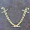
The con rods finished, little end bushings pressed in and waiting for the split big end bearing shells.
The big end bearing shells, the next job. Bronze is called for and I think I have some, if I can't find it brass will have to do. |


 to raise/support them to/at a suitable height?


Please login to post a reply.
Magazine Locator
Want the latest issue of Model Engineer or Model Engineers' Workshop? Use our magazine locator links to find your nearest stockist!
Sign up to our Newsletter
Sign up to our newsletter and get a free digital issue.
You can unsubscribe at anytime. View our privacy policy at www.mortons.co.uk/privacy
Latest Forum Posts
- *Oct 2023: FORUM MIGRATION TIMELINE*
05/10/2023 07:57:11 - Making ER11 collet chuck
05/10/2023 07:56:24 - What did you do today? 2023
05/10/2023 07:25:01 - Orrery
05/10/2023 06:00:41 - Wera hand-tools
05/10/2023 05:47:07 - New member
05/10/2023 04:40:11 - Problems with external pot on at1 vfd
05/10/2023 00:06:32 - Drain plug
04/10/2023 23:36:17 - digi phase converter for 10 machines.....
04/10/2023 23:13:48 - Winter Storage Of Locomotives
04/10/2023 21:02:11 - More Latest Posts...
- View All Topics
Support Our Partners


Shopping Partners
Subscription Offer

Latest "For Sale" Ads
- Reeves** - Rebuilt Royal Scot by Martin Evans
by John Broughton
£300.00 - BRITANNIA 5" GAUGE James Perrier
by Jon Seabright 1
£2,500.00 - Drill Grinder - for restoration
by Nigel Graham 2
£0.00 - WARCO WM18 MILLING MACHINE
by Alex Chudley
£1,200.00 - MYFORD SUPER 7 LATHE
by Alex Chudley
£2,000.00 - More "For Sale" Ads...
Latest "Wanted" Ads
- D1-3 backplate
by Michael Horley
Price Not Specified - fixed steady for a Colchester bantam mark1 800
by George Jervis
Price Not Specified - lbsc pansy
by JACK SIDEBOTHAM
Price Not Specified - Pratt Burnerd multifit chuck key.
by Tim Riome
Price Not Specified - BANDSAW BLADE WELDER
by HUGH
Price Not Specified - More "Wanted" Ads...
Get In Touch!
Do you want to contact the Model Engineer and Model Engineers' Workshop team?
You can contact us by phone, mail or email about the magazines including becoming a contributor, submitting reader's letters or making queries about articles. You can also get in touch about this website, advertising or other general issues.
Click THIS LINK for full contact details.
For subscription issues please see THIS LINK.
Digital Back Issues


Donate

 Register
 Log-in
Model Engineer Magazine
- Percival Marshall
- M.E. History
- LittleLEC
- M.E. Clock

ME Workshop
- An Adcock
- & Shipley
- Horizontal
- Mill

Subscribe Now
- Great savings
- Delivered to your door

Pre-order your copy!
- Delivered to your doorstep!
- Free UK delivery!
All Forum Topics > Stationary engines > Three Cylinder Steam Aero Engine