Forum sponsored by:

How to machine an ellipse
| Neil Wyatt | 16/07/2018 14:46:09 |
 19226 forum posts 749 photos 86 articles | Posted by Ian P on 16/07/2018 11:04:42:
Posted by Neil Wyatt on 16/07/2018 10:50:25:
Ken, The jig was just a random lump of brass of the right diameter. As jason says it was a gland, so the shape is cosmetic. It was set up by eye, all that matters is the two screw holes are the right distance apart and on the same radius. The ends were finished by filing.
None of the posts in this topic seem to be related to 'Ken' so I am wondering if somehow my PC does not see all the post. Neil's reply does refer to an ellipse so what am I missing? Ian P
Keith, not Ken. Sorry Keith, and I think it may have been cast iron... |
| Keith Rowe | 16/07/2018 16:47:24 |
| 20 forum posts 2 photos | Thank you JasonB for your kind offer the bolts will be 7BA and 14.8mm apart and the hole in the middle 3.5mm thank you.I did not know boiling water will affect brass something else I have learnt.It will take me some time to take in all the information you have all provided. Once again many many thanks to all, I do appreciate the time and effort you have invested in me and I will try to repay this by becoming better at the hoby. Keith.
|
| JasonB | 16/07/2018 19:08:02 |
 25215 forum posts 3105 photos 1 articles | Well those sizes seem to fit together quite nicely and will come out of 7/8" (22.2mm) stock This first picture shows part of my construction drawing, the red line is the outline of the gland made up from two 19mm radius arcs (38mm dia circles) and the ends rounded to 3.6mm radius. You hopefully can just see a dashed green line that almost matches the red outline which is actually a true ellipse so the made up one comes close enough for most things. Click on all pictures and they should come up larger.
I added a boss if you need one and this is what the finished flange will look like
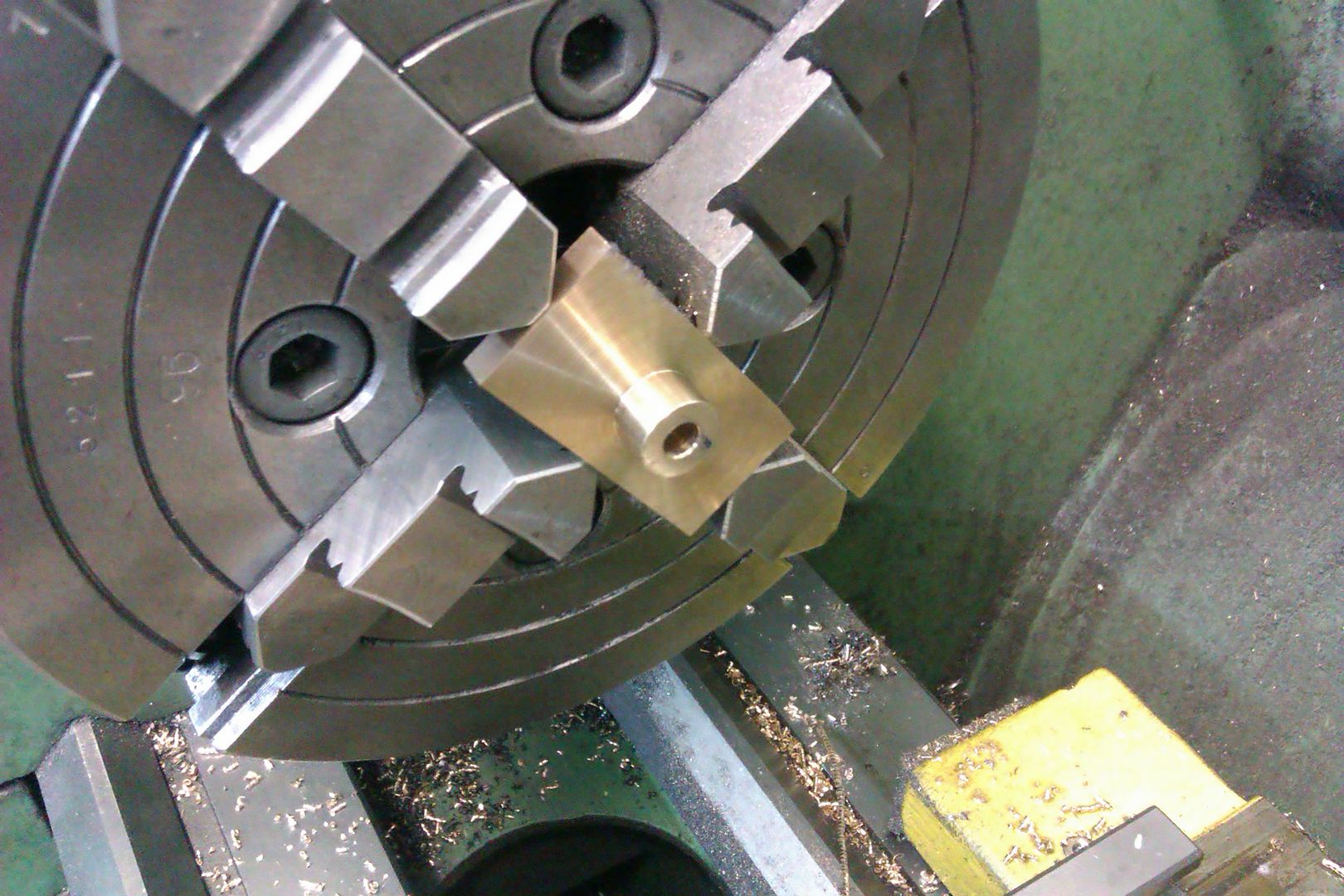
For the Jig a piece of bar 38mm diameter or larger, I have shown 38 as it matched the curve of the side of the gland and is also more or less 1.5" diameter which you may have to hand. Length is not critical but enough to hold so 20mm plus. Face off then mark out and drill and tap two holes 7BA in the positions shown. replace in chuck and skim down the end to 38mm dia and zero the handwheel dial. Screw on the flange and turn one side to the zero setting then reverse it round and do the other side
The flange is just turned 22mm round and the two holes drilled and will take on the shape as you turn it on the jig. Finally file the ends round using filing buttons.
And this is the drawing to work to PDF to download or just use this image
Edited By JasonB on 16/07/2018 19:13:14 Edited By JasonB on 16/07/2018 19:16:13 |
| SillyOldDuffer | 16/07/2018 19:29:17 |
| 10668 forum posts 2415 photos | Alternatively, if an approximation is acceptable, this lozenge shape can be created on a milling machine with 4 straight cuts and 4 rotations. Easiest to do to a rod held vertically in a rotary chuck. The shape, at least on a small scale in brass, can be quickly made with a file.
True ellipse shown in red for comparison. Construction based on circles and straight lines shown in orange. Dave |
| JasonB | 16/07/2018 19:35:34 |
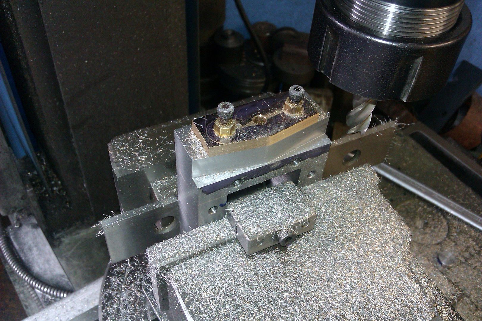
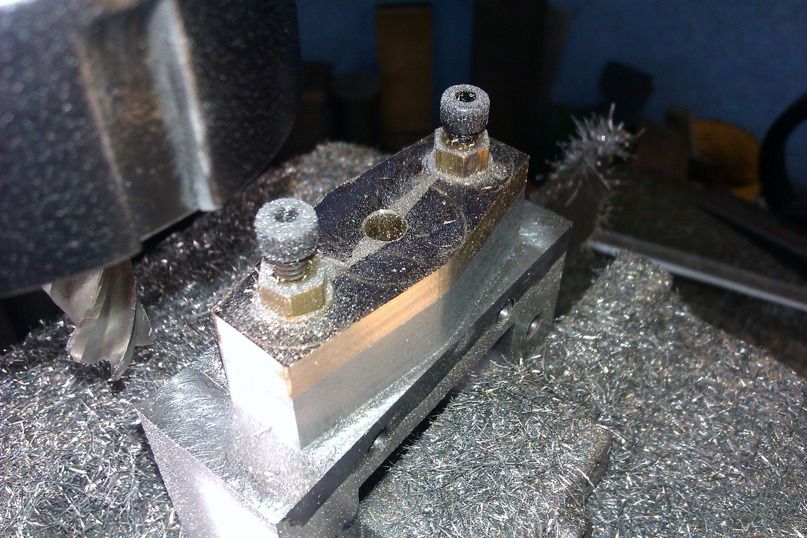
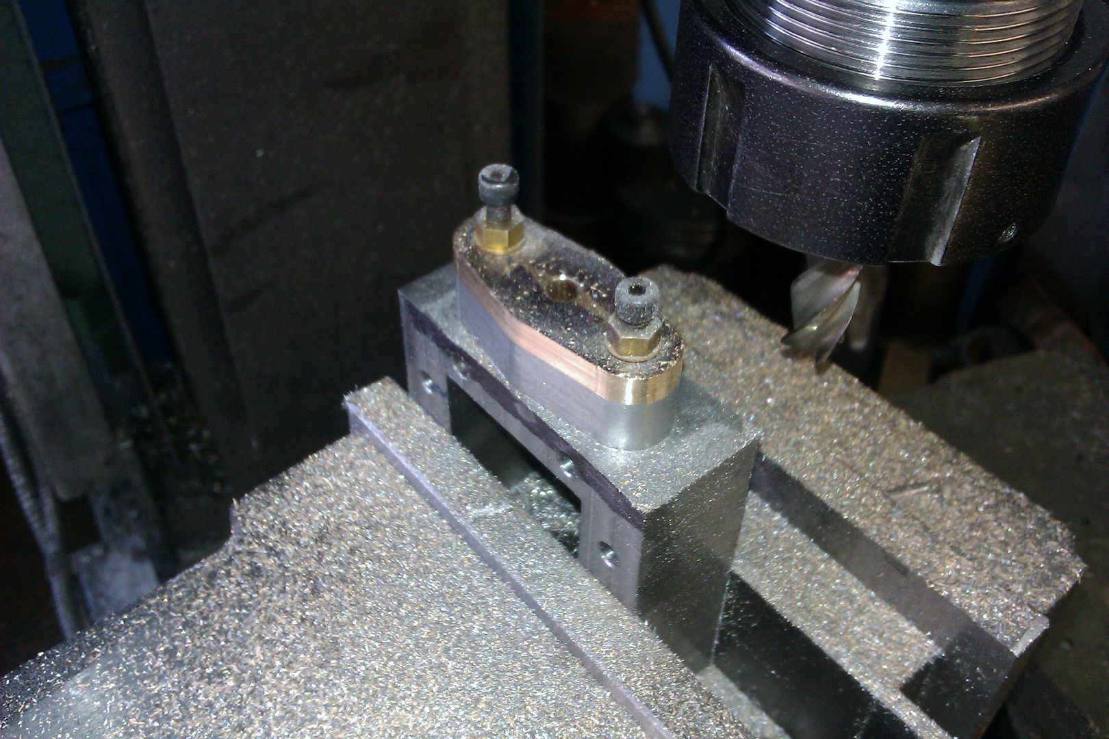
25215 forum posts 3105 photos 1 articles | This shows one being done as per Dave's sketch
|
| Dalboy | 16/07/2018 20:40:36 |
 1009 forum posts 305 photos | There is a jig that woodturner make which will turn an eclipse whether it could be adapted for use on an metal working lathe I do not know. I am sure that I have a book in my library that has a jig in it if I can find it I will let you know |
| John Haine | 16/07/2018 23:11:20 |
| 5563 forum posts 322 photos | This might be of interest |
| Dalboy | 17/07/2018 09:48:06 |
1009 forum posts 305 photos | I found the jig but I don't think that it will be what is needed. Here is the diagram of it can not show any more.
|
| Hopper | 17/07/2018 10:14:59 |
 7881 forum posts 397 photos | Yet another way of doing it is with steel filing buttons made up, one large pair that fit over the centre part, and two small pairs that fit over a screw through each stud hole. Often the buttons need flats filing on the them where they meet so they fit the space. As often happens, takes way longer to make the buttons than to file the little bit of brass down to the resulting shape. But works well for multiple flanges. By rocking the file a bit, a good elliptical shape can be achieved, rather than the flat sides between the three radiuses. If you make the buttons from silver steel you can even harden them. Otherwise, I sometimes use mild steel and file carefully so as not to damage them. I don't have a mill so this method is handy for me. Edited By Hopper on 17/07/2018 10:15:56 |
| Mike Poole | 17/07/2018 11:42:01 |
 3676 forum posts 82 photos | To machine an ellipse that is a true shape and accurate size you may have to go for CNC. For most practical purposes the solutions offered for an approximate ellipse would be completely satisfactory. The cross and pin jigs for routing work very well but the solution doesn't seem to have an equivalent for machining metal. I suppose that prior to NC a copy mill and a template would be used, it seems that an ellipse is not often machined and just left as cast where it does come up in a design. CNC does allow complex curves to be accurately machined and the need to do this from the aircraft industry provided the force to develop Numerical Control and funded mainly by the US military it was soon making parts. Mike |
| Tim Stevens | 17/07/2018 16:24:43 |
 1779 forum posts 1 photos | A simple way to draw an ellipse without doing complex sums (etc) is this: Draw out a circle on graph paper using a pair of compasses, with the centre on one of the major crossing points on the paper, and the radius to the size of the longer diameter required - or some handy multiple of it. Your circle will be divided into strips by the lines on the paper, and we need to look only at the more heavily printed ones, and only those which run up and down the page. Take each such heavy line in turn, and measure the length between the ends where the circle cuts it. This can be done without a ruler or calliper by counting the squares on the paper (but not quite so exactly). Divide this distance by 4. Yes, that is a sum, I know, and a calculator makes this bit quicker. Measure this 1/4 distance up from the equator of your circle, and make a dot, and then do the same down from the equator. Do this for each of the heavy vertical lines, and you will produce an oval ring of dots. Join them up and there is your ellipse. It doesn't matter whether the diameter of your circle fits exactly with the squares on the paper, or even whether the starting centre is exactly lined up with a heavy line - the method I set out above does not need these details, but it does make the job quicker as the four quarters of the ellipse can then rely on the same measurements each side - you can even fold the first quarter over and mark through, if you are a precise folder. And if you have no graph paper, use lined writing paper with the lines going up and down, and a ruler for measuring. The result is an ellipse with the vertical diameter just half the horizontal. If you need a different proportion, don't use half the vertical distances, but some other fraction or decimal to do the calculation. If your fraction is larger than 1/2, the ellipse will be more nearly round, and if your chosen fraction is smaller the ellipse will be more pointy-ended. Useful, sometimes, if for example you need to make a tidy looking car Nationality Plate for a trip abroad (as I did, you might guess). And while I am writing, you can generate a true ellipse using a 'trammel' comprising a pair of followers (like T-nuts) running in two right-angle slots in a cross-shaped construction (one in each slot). Join the two followers with a bar (which can stick out each end if you like) and any point on the bar will move in an ellipse as you slide the two followers along. Winding the handles of your manual mill to trace the correct outline keeping the followers in the slots would make an interesting exercise - rather more difficult than scratching your head and patting your belly, I reckon. Hours of untrammelled joy ... Regards, Tim Edited By Tim Stevens on 17/07/2018 16:26:21 |
| JasonB | 17/07/2018 16:31:18 |
25215 forum posts 3105 photos 1 articles | As most on here will be using a computer to post it is also very easy to just draw out what you need, print and stick it to your material. No need for fancy CAD, something like Windows Paint will do ellipses |
| Keith Rowe | 18/07/2018 10:34:37 |
| 20 forum posts 2 photos | BIG thank you to you all, JasonB I have download your PDF many thanks. If the house next door comes up for sale I will post it here in the hope one of you will move in !! |
| Bazyle | 18/07/2018 13:39:08 |
 6956 forum posts 229 photos | If you are after a curve rather than a true ellipse have a think about a steam engine connecting rod. One end goes in a circle and the other end goes in a line. In between you get points following a curve (asymmetrical). A little ingenuity with a rotary table on a mill should achieve the required effect. |
| duncan webster | 18/07/2018 15:53:37 |
| 5307 forum posts 83 photos | Posted by Bazyle on 18/07/2018 13:39:08:
If you are after a curve rather than a true ellipse have a think about a steam engine connecting rod. One end goes in a circle and the other end goes in a line. In between you get points following a curve (asymmetrical). A little ingenuity with a rotary table on a mill should achieve the required effect. angularity of the con rod results in an asymmetric ellipse, sort of egg shape. If the con rod were long enough it might not matter. |
| Bazyle | 18/07/2018 17:42:18 |
6956 forum posts 229 photos | You would just turn it round after doing one end. Another candidate is a rose engine although that sort of assumes you have a master ellipse. Industrial users might have had an Armag profiling tool, but again a master is needed. Edited By Bazyle on 18/07/2018 17:47:36 |
| Michael Gilligan | 18/07/2018 18:07:43 |
 23121 forum posts 1360 photos | Posted by Bazyle on 18/07/2018 17:42:18:
Another candidate is a rose engine although that sort of assumes you have a master ellipse. .
MichaelG. . Here is a concise explanation: https://chestofbooks.com/home-improvement/workshop/Turning-Mechanical/Advertisements-Vol-3-Part-2.html#.UQxbQmtYCK0 ... and someting a little more complex: http://ornamentalroseengine.com/rose/rose2/holtz.php Edited By Michael Gilligan on 18/07/2018 18:22:33 Edited By Michael Gilligan on 18/07/2018 18:30:46 |
| Michael Gilligan | 18/07/2018 22:29:55 |
23121 forum posts 1360 photos | Posted by Derek Lane 2 on 17/07/2018 09:48:06:
I found the jig but I don't think that it will be what is needed. Here is the diagram of it can not show any more.
. Thanks, Derek I've located the web-page that describes it : **LINK** http://www.aawcontentsource.org/aaw_cs1_pdf/AW3006p28-35.pdf The design appears to be a wood-turners version of the Holtzapffel Ellipse Chuck : **LINK** http://www.ornamentalturning.co.uk/ellipse_chuck.pdf MichaelG.
|
| Bazyle | 18/07/2018 23:01:44 |
6956 forum posts 229 photos | MG is correct, I think a rose engine using a thin rectangle pattern and a large diameter disc rubber will work. I was thinking of a simple rubber just following the pattern. |
| Michael Gilligan | 19/07/2018 07:06:29 |
23121 forum posts 1360 photos | Thanks for your gracious acknowledgement, Bazyle. Prior to seeing that, I did suddenly wonder if you were being devilish by mentioning a 'master ellipse' [the circle being, of course, a 'special case' of the ellipse]. MichaelG. |


Please login to post a reply.
Magazine Locator
Want the latest issue of Model Engineer or Model Engineers' Workshop? Use our magazine locator links to find your nearest stockist!
Sign up to our Newsletter
Sign up to our newsletter and get a free digital issue.
You can unsubscribe at anytime. View our privacy policy at www.mortons.co.uk/privacy
Latest Forum Posts
- *Oct 2023: FORUM MIGRATION TIMELINE*
05/10/2023 07:57:11 - Making ER11 collet chuck
05/10/2023 07:56:24 - What did you do today? 2023
05/10/2023 07:25:01 - Orrery
05/10/2023 06:00:41 - Wera hand-tools
05/10/2023 05:47:07 - New member
05/10/2023 04:40:11 - Problems with external pot on at1 vfd
05/10/2023 00:06:32 - Drain plug
04/10/2023 23:36:17 - digi phase converter for 10 machines.....
04/10/2023 23:13:48 - Winter Storage Of Locomotives
04/10/2023 21:02:11 - More Latest Posts...
- View All Topics
Support Our Partners


Shopping Partners
Subscription Offer

Latest "For Sale" Ads
- Reeves** - Rebuilt Royal Scot by Martin Evans
by John Broughton
£300.00 - BRITANNIA 5" GAUGE James Perrier
by Jon Seabright 1
£2,500.00 - Drill Grinder - for restoration
by Nigel Graham 2
£0.00 - WARCO WM18 MILLING MACHINE
by Alex Chudley
£1,200.00 - MYFORD SUPER 7 LATHE
by Alex Chudley
£2,000.00 - More "For Sale" Ads...
Latest "Wanted" Ads
- D1-3 backplate
by Michael Horley
Price Not Specified - fixed steady for a Colchester bantam mark1 800
by George Jervis
Price Not Specified - lbsc pansy
by JACK SIDEBOTHAM
Price Not Specified - Pratt Burnerd multifit chuck key.
by Tim Riome
Price Not Specified - BANDSAW BLADE WELDER
by HUGH
Price Not Specified - More "Wanted" Ads...
Get In Touch!
Do you want to contact the Model Engineer and Model Engineers' Workshop team?
You can contact us by phone, mail or email about the magazines including becoming a contributor, submitting reader's letters or making queries about articles. You can also get in touch about this website, advertising or other general issues.
Click THIS LINK for full contact details.
For subscription issues please see THIS LINK.
Digital Back Issues


Donate

 Register
 Log-in
Model Engineer Magazine
- Percival Marshall
- M.E. History
- LittleLEC
- M.E. Clock

ME Workshop
- An Adcock
- & Shipley
- Horizontal
- Mill

Subscribe Now
- Great savings
- Delivered to your door

Pre-order your copy!
- Delivered to your doorstep!
- Free UK delivery!
All Forum Topics > Beginners questions > How to machine an ellipse