Forum sponsored by:

Form Tool or other way?
| James Jenkins 1 | 19/05/2016 22:46:25 |
 162 forum posts 7 photos | Hi Everyone, Thank you, some more really helpful comments. The machine is this one: **LINK** (Click to play the video). I am replacing the existing old 1425rpm 1/4hp 240v motor, with a 2800rpm, 36v, 250w motor as we are working to make all the electric machines in the studio solar powered (except the weaving looms which are treadle powered!). To be honest the existing drive pulley is a V profile, but I assumed that this was used simply because that is what the crofter had to hand (the machine is from the Isle of Lewis on northern west coast of Scotland where everything is bit Heath Robinson!). But perhaps not... certainly the driven pulley, which is 7", is also V profile. Perhaps this is my answer? James Edited By James Jenkins 1 on 19/05/2016 22:46:51 Edited By James Jenkins 1 on 19/05/2016 22:47:34 Edited By James Jenkins 1 on 19/05/2016 22:47:52 |
| Michael Gilligan | 19/05/2016 23:11:56 |
 23121 forum posts 1360 photos | Posted by Roderick Jenkins on 19/05/2016 21:13:08:
Posted by James Jenkins 1 on 19/05/2016 20:31:24:
The measurements came from a commercial pulley design and they seem to make the internal radius just over that of the band, so who am I to argue? Obviously I don't know the application, but for round belts it is usual to make Idler pulleys with a groove radius slightly larger than the belt but to use a V section for Drive pulleys. HTH, Rod . James, I agree 100% with Rod's comment ... and I think you have a wonderful project there Best wishes for its success !! MichaelG. |
| John McNamara | 20/05/2016 00:43:25 |
 1377 forum posts 133 photos | Old pre second world war Singer sewing machine heads had v drive pulleys, they were usually driven by round leather belting, this allowed the metal staple used to join them to pass through the V if set correctly. The round belt would slowly form into a rounded top and bottom V. If you can find it the best belting has a little hair on the top surface. It was left there to prove that the belt was cut from the top layer of the hide. A good belt would last for years of daily industrial use. |
| James Jenkins 1 | 20/05/2016 06:52:26 |
162 forum posts 7 photos | Thanks everyone, it seems a V profile is the the way to go and will be easier to turn as well. A double win! I'll revise the drawing and post a pic of the finished item when done. Thanks again everyone, really, really appreciate it. James |
| James Jenkins 1 | 20/05/2016 18:27:35 |
162 forum posts 7 photos | Here is my revised design, to fit on the 8mm shaft of the motor. Secured by the left handed thread and a grub screw down to the flat. I realise the old hands will think this way over the top for 'a simple bloody pulley', but it does help me to get my head around it!
|
| John Haine | 20/05/2016 19:26:11 |
| 5563 forum posts 322 photos | Why do you have a LH thread? Seems a bit OTT to me. If there's a flat on th shaft anyway that should do the trick. I doubt the motor would come with a LH thread cut, so how would you make it? Also 8mm is 0.315 inches not that the odd thous matter. |
| James Jenkins 1 | 20/05/2016 19:35:25 |
162 forum posts 7 photos | Hi John, Thanks for that. The motor has a LH thread on the end of the shaft... I agree the flat would be enough, but I thought as the thread was there I might as well use it. Thanks for the heads up on the math - I copied the text from the flange width and forgot to change it - I guess because it looked done. I'll change it now, so new readers won't notice! James |
| John Reese | 20/05/2016 19:42:35 |
 1071 forum posts | The change to a V groove is a wise decision. You need the wedging action to keep the belt from slipping. The driven pulley also needs a V groove unless there is a long arc of contact. I suggest 34* to 38* included angle for the groove. |
| Emgee | 20/05/2016 19:47:47 |
| 2610 forum posts 312 photos | James A drop or two of threadlock won't go amiss on the M4 screw for additional security. Nice project and it's good to know there are still such people as yourself to keep our heritage working. Emgee |
| Neil Wyatt | 20/05/2016 20:29:46 |
 19226 forum posts 749 photos 86 articles | I would make the groove narrower and not flat bottomed. No pojnt making eth top of the vee more than a smidgin wider than the belt. Neil |
| Dave Martin | 21/05/2016 10:44:34 |
| 101 forum posts 11 photos | James - can't offer any more advice on the pulley but super-impressed with your machinery restorations. Dave |
| Tim Stevens | 21/05/2016 11:26:18 |
 1779 forum posts 1 photos | How about rotating the workpiece slowly on a rotary table or dividing head while a cylindrical milling cutter nibbles away at the groove? And if the groove needs to be a non-standard diameter, set the cutter at a slight angle. Not quite an exact 'circular' groove in the latter case, but does that matter? Cheers, Tim |
| John Reese | 21/05/2016 23:37:06 |
1071 forum posts | James, There is no reason to avoid a flat at the bottom of the groove. Plunge a parting tool at the center of the groove. Take additional plunge cuts with the parting tool to get close to the V contour. Using the compound feed a tool down each side of the V. John |
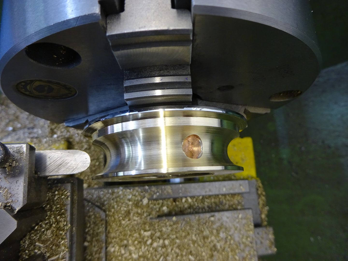
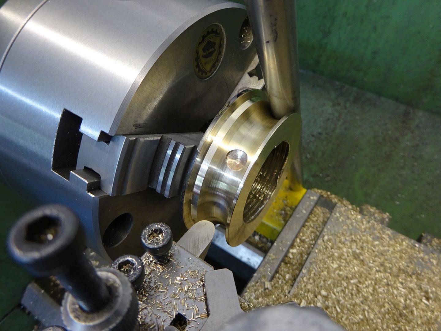
| James Jenkins 1 | 23/05/2016 15:16:23 |
162 forum posts 7 photos | Hi all, Thanks so much for your advice everyone. Really helpful. Thank you also for your kind words regarding the weaving mill, I do hope that once we get set up you'll come and see them in action if you are ever in Suffolk. I have been thinking about the operations to make the pulley, watched a couple of videos etc. Most seem to use a mandrel for turning these pulley's between centres, with the piece glued on or fixed on with a press. However, I cannot make a hole larger than 6.8mm and that feels too thin. So after going through a few options in my mind, this is the draft procedure I currently thinking of: 1) Mount the the 2 1/2" diameter x c4" long bar in the 3 jaw chuck, center drill and mount onto a half centre 2) Working at the tail stock end, size the 2" diameter of the pulley into the bar, with sufficient clearance for further work, and cut the angled faces (Parting tool to depth, a series of straight cuts coming out to decreasing depths and then angled cuts to smooth). 3) Reduce the diameter of the flange to 1" and face the flange and the side of the main section. Break edges 4) Either part off (or hacksaw off) the pulley with 1/4" waste to the left. Mount in to the three jaw chuck, with the flange facing out. . 5) Successively drill up to 6.8mm, finishing inside the waste piece (to protect the rear of the chuck) 6) Turn the piece around in the chuck, using the flange as a mount and bring up the half centre on the tail stock to support the work. Remove the 1/4" and face. Break Edges. 7) Increase the bore to 7.8mm to a depth of 0.625" (end of the thread) and then ream to 8mm. 8) Remove from the lathe to tap the end thread and drill/tap the grub screw hole. Am I about right or way, way off? James Edited By James Jenkins 1 on 23/05/2016 15:17:00 Edited By James Jenkins 1 on 23/05/2016 15:18:11 |
| JasonB | 23/05/2016 15:32:34 |
 25215 forum posts 3105 photos 1 articles | I would try and do the hole and V at one setting to keep things concentric. 1. cut off a bit of your bar say 1/4" overlength. 2. Hold in 3-jaw face off end and form reduced 1" dia of the boss. 3. Reverse in chuck so now holding by 1" dia. Face to length then form hole as described above. 4. Bring up tailstock support, turn 2" OD of pully 5, Cut Vee as described above.
Out of interest I needed to make a bender for some 1/2" tube yesterday, found a bit of scrap brass and used a 3/8" bull nossed HSS tool that I already had to form the 1/2" concave, just offering up the tube a couple of times and using eyeball and hand co-ordination for the rest.
|
| Neil Wyatt | 23/05/2016 19:24:56 |
19226 forum posts 749 photos 86 articles | Posted by John Reese on 21/05/2016 23:37:06:
James, There is no reason to avoid a flat at the bottom of the groove. There is if using a compliant belt that moulds to the shape of the groove, if it 'bottoms out' it will become more likely to slip as the wedging action with increased tension is much reduced. Neil |
| James Jenkins 1 | 25/05/2016 19:35:42 |
162 forum posts 7 photos | Hi Jason, thanks so much for that. Really helpful. Thank you also Neil - helpful advice. I started to work on sharpening up the tools that came with it. However, they are only tool steel and require quite a bit of work to get them in shape. So I am thinking I should get some HSS ones. In an ideal world I wouldn't buy a whole set now, but the prices for a set of 8 are often the same as 4 individual ones. These are the ones I am thinking of: http://www.myford.co.uk/acatalog/1_2__Tooling.html http://www.chronos.ltd.uk/acatalog/Sets_of_HSS_Lathe_Tools.html (10mm or 12mm? - made by Soba) Or second hand Myford (doesn't actually say HSS, but presumably is?) http://www.ebay.co.uk/itm/Original-Myford-boat-with-11-tool-cutters-Direct-from-myford-stuff-/182128615827?hash=item2a67b62193:g:YQkAAOSwvU5XNHpG I wouldn't normal buy new, but I don't really want to spend days regrinding the tools to the correct angle… I am assuming the new ones will come nicely set up. Any thoughts, ideas, alternative suggestions? Edited By James Jenkins 1 on 25/05/2016 19:37:11 Edited By James Jenkins 1 on 25/05/2016 19:54:56 |

Please login to post a reply.
Magazine Locator
Want the latest issue of Model Engineer or Model Engineers' Workshop? Use our magazine locator links to find your nearest stockist!
Sign up to our Newsletter
Sign up to our newsletter and get a free digital issue.
You can unsubscribe at anytime. View our privacy policy at www.mortons.co.uk/privacy
Latest Forum Posts
- *Oct 2023: FORUM MIGRATION TIMELINE*
05/10/2023 07:57:11 - Making ER11 collet chuck
05/10/2023 07:56:24 - What did you do today? 2023
05/10/2023 07:25:01 - Orrery
05/10/2023 06:00:41 - Wera hand-tools
05/10/2023 05:47:07 - New member
05/10/2023 04:40:11 - Problems with external pot on at1 vfd
05/10/2023 00:06:32 - Drain plug
04/10/2023 23:36:17 - digi phase converter for 10 machines.....
04/10/2023 23:13:48 - Winter Storage Of Locomotives
04/10/2023 21:02:11 - More Latest Posts...
- View All Topics
Support Our Partners


Shopping Partners
Subscription Offer

Latest "For Sale" Ads
- Reeves** - Rebuilt Royal Scot by Martin Evans
by John Broughton
£300.00 - BRITANNIA 5" GAUGE James Perrier
by Jon Seabright 1
£2,500.00 - Drill Grinder - for restoration
by Nigel Graham 2
£0.00 - WARCO WM18 MILLING MACHINE
by Alex Chudley
£1,200.00 - MYFORD SUPER 7 LATHE
by Alex Chudley
£2,000.00 - More "For Sale" Ads...
Latest "Wanted" Ads
- D1-3 backplate
by Michael Horley
Price Not Specified - fixed steady for a Colchester bantam mark1 800
by George Jervis
Price Not Specified - lbsc pansy
by JACK SIDEBOTHAM
Price Not Specified - Pratt Burnerd multifit chuck key.
by Tim Riome
Price Not Specified - BANDSAW BLADE WELDER
by HUGH
Price Not Specified - More "Wanted" Ads...
Get In Touch!
Do you want to contact the Model Engineer and Model Engineers' Workshop team?
You can contact us by phone, mail or email about the magazines including becoming a contributor, submitting reader's letters or making queries about articles. You can also get in touch about this website, advertising or other general issues.
Click THIS LINK for full contact details.
For subscription issues please see THIS LINK.
Digital Back Issues


Donate

 Register
 Log-in
Model Engineer Magazine
- Percival Marshall
- M.E. History
- LittleLEC
- M.E. Clock

ME Workshop
- An Adcock
- & Shipley
- Horizontal
- Mill

Subscribe Now
- Great savings
- Delivered to your door

Pre-order your copy!
- Delivered to your doorstep!
- Free UK delivery!
All Forum Topics > Beginners questions > Form Tool or other way?