Forum sponsored by:

Correct Performance of Fixed Steadies
| martyn nutland | 17/12/2015 14:28:15 |
| 141 forum posts 10 photos | Hello Martin with an 'i' I never supposed that steadies were anything to do with centering work. I thought they were to resist the deflection of long thin work under the pressure of the cutting tool; either, in the case of a fixed steady, while one performed an operation on a relatively short section of the work, or, in the case of a travelling steady, if one was transversing a much longer section with the tool. What I didn't know was that you needed to machine an accurate bearing surface (a journal, if you like) on which the steady could bear. I assumed that if you bought a piece of bar from the likes of Noggin End or Mallard or whoever, its diameter and parallelism would be within sufficient limits of accuracy for you to attach the steady and turn whatever was needed. Thanks for that enlightenment. Martyn with a 'y'.
|
| Howard Lewis | 17/12/2015 16:35:20 |
| 7227 forum posts 21 photos | The comments about paint on mating surfaces are very pertinent. Recently I had dealings with a Chester Conquest, and found that the surfaces that mate with the bed on both the Tailstock, and the Fixed Steady were covered in overspray. A little rubbing, with some Emery removed the overspray And Yes, I did wipe off the dust (Hopefully all of it). The plates that clamp the tailstock, and steady to the bed look a bit flimsy, to my mind, but that can be remedied in time. Other jobs intervene, currently. The Model B does have a fairly large centre height so, don't be overambitious when turning the longer length of the work. Better to take smaller cuts without deflecting the steady than to rush and make a scrapper. a) you do need to clamp the work with just a short piece protruding from the chuck, and turn to finish diameter, for a length that will allow clearance for the tool behind the steady, to turn the rest of the length. b) Set up the steady to this diameter. c)The work should then be pulled out of the chuck far enough to to turn the length required, as the steady is moved back towards the tailstock. d) When all is ready to start turning, clamp the steady, and then tighten the chuck. e) Oil the fingers of the steady, and then start turning. Don't let the fingers run dry! With a bit of care and luck, you will achieve the required result. Howard |
| JasonB | 17/12/2015 17:00:26 |
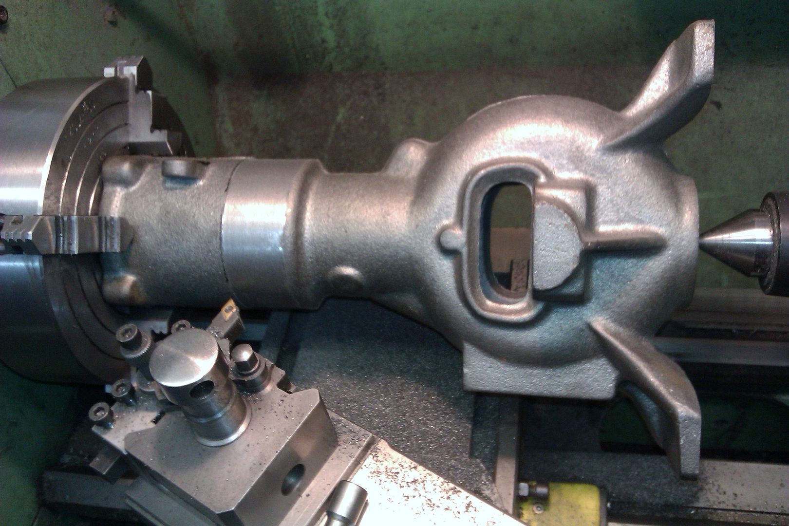
 25215 forum posts 3105 photos 1 articles | The above only really works if the material is short and slender enough to fit within the chuck body or very slender so it will pass down the spindle bore. Andrews example would not fit any further into the chuck and my example simply won't fit in a chuck, in these cases you need to get a bit more inventive I've not had problems running "as supplied" bright mild steel in the steady, probably could not cut a better bearing surface on it without using a steady anyway |
| Neil Wyatt | 17/12/2015 17:16:31 |
 19226 forum posts 749 photos 86 articles | Posted by martyn nutland on 17/12/2015 14:28:15: . I assumed that if you bought a piece of bar from the likes of Noggin End or Mallard or whoever, its diameter and parallelism would be within sufficient limits of accuracy for you to attach the steady and turn whatever was needed. That's a fair assumption, but it is important the steady is accurately centred because if teh steady forces the work off centre bad things will happen. For long cylindrical work I set the steady close to the chuck, then slide t along to the end. Not possible with Jason's hopper engine so you would need to set the bearing surface running true with a dial indicator or more likely he took a skim off it before applying the steady. Neil |
| Emgee | 17/12/2015 17:25:21 |
| 2610 forum posts 312 photos | Denford steady in use, nylon collar fitted over work and clamped on with a Jubilee clip, saves running steel fingers on the aluminium tube of the tuned pipe. Emgee |
| JasonB | 17/12/2015 17:31:39 |
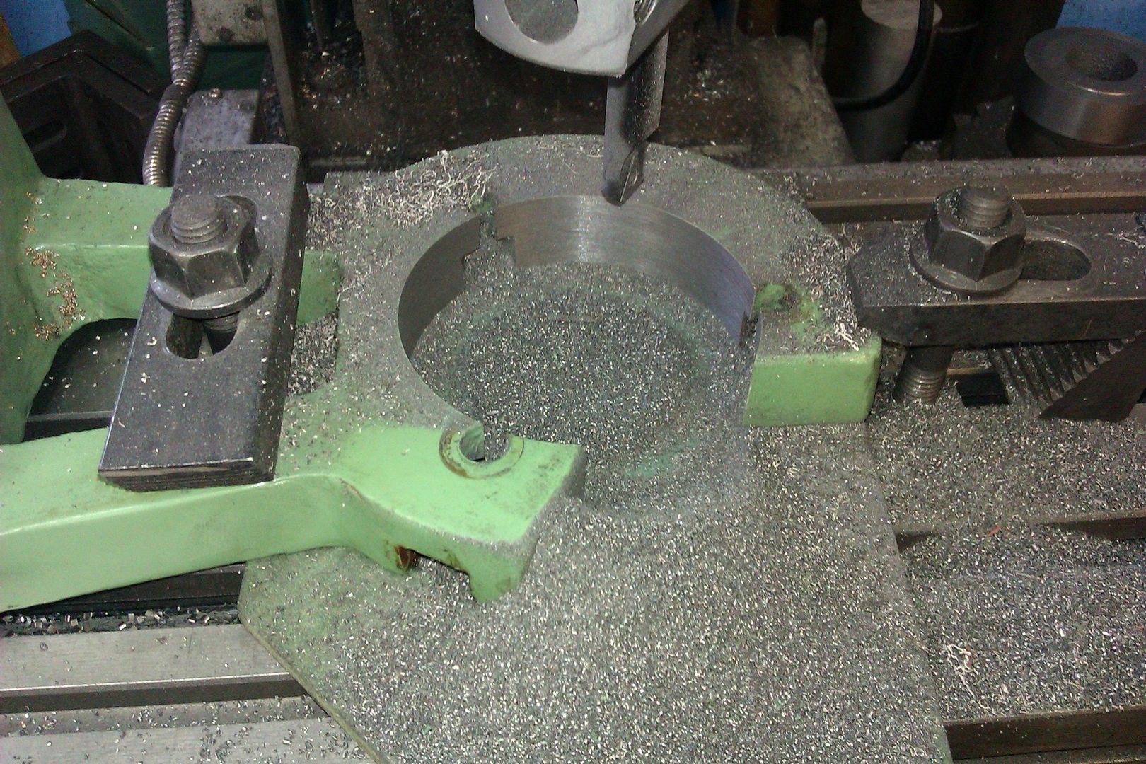
25215 forum posts 3105 photos 1 articles | A dial indicator may not show true, you could quite happily set the work up in the steady but 1/4" too low and the DTI needle would not move. Something like a co-axial indicator held in teh tailstock and rotated by hand would give a better indication if your work is set to the lathe axis. Half right Neil, I did skim the casting but not with the piece set up as it was for boring, so the skimmed surface had to be clocked true.
Oh and you sometimes need machine the steady to suit the job
Edited By JasonB on 17/12/2015 17:32:17 |
| martyn nutland | 17/12/2015 17:34:10 |
| 141 forum posts 10 photos |
I think I'm grasping this. Go for solid. Turn a 'journal' on which the steady fingers can bear. Etcetera. However, I got the Chester contraption solid(ish) tonight with much packing. I know that was against the advice, but 'no-way' was it going to firm up without. Now I can see, without even taking a measurement, it's twisted and has been from 'new', or from the time Chester used it and then sold it to me as 'new'. I think I'll be alright now if I get a decent steady. I rather fancy Neil's from Machine Mart and intend to investigate if it actually does fit a Super B. Thanks to everyone. Have learnt a lot. Martyn (Merry Kissmuss)
|
| JasonB | 17/12/2015 17:49:57 |
25215 forum posts 3105 photos 1 articles | Posted by martyn nutland on 17/12/2015 17:34:10:
I think I'll be alright now if I get a decent steady. I rather fancy Neil's from Machine Mart and intend to investigate if it actually does fit a Super B.
It will be about 60mm too low as the CL500 is 305mm ctr height |
| bodge | 17/12/2015 18:23:04 |
| 186 forum posts 3 photos | Steady & tapping grade tallow available on ebay, { google tallow} Have not tried it, bodge |
| Emgee | 17/12/2015 18:41:23 |
| 2610 forum posts 312 photos | If using a fixed steady with chuck mounted work if the steady fingers are not truly holding the job on centre there is a strong possibility of the job "walking" out of the chuck. This action will be apparent when facing, the cuts get increasingly heavier until you realise what's happening and too much has been removed. Steadies that hinge open are normally stiffer than open sided ones but this may not always be the case. Emgee |
| martyn nutland | 18/12/2015 10:04:58 |
| 141 forum posts 10 photos |
Mornin' All Denouement? Have just run Super B lathe expirementally with Chester fixed steady and a piece of approximately 10 inch long EN24T in a 16mm collet chuck. No machined surface for the fingers for this purpose. Everything rock solid, no movement on steady, no movement on 'work', no loosening, no heat, no perceptible run out. Kept lathe going for about four minutes with no change. What I've done is position the fingers first so they bear squarely on the work and initially tightened them up. Located the fixed gyb (operator side of the lathe) hard against the bed, then I've slewed the gyb on the far side at an angle to the bed, wedged it with a piece of packing and tightened that up hard. Then finally tightened the fingers up hard. I also have a packing piece between the foot of the steady and centre of the bed which eliminates any axial rock. Not elegant, but it's working. Martyn
|
| duncan webster | 18/12/2015 22:02:28 |
| 5307 forum posts 83 photos | All this talk of steadies reminds me that I bought the one in the picture many years ago intending to adapt it to fit my Myford 254S, but then I found a much better one, so this has been in a cupboard ever since. If anyone wants it it's yours for the cost of the postage, or pick up in north Cheshire |
| Neil Wyatt | 19/12/2015 13:20:24 |
19226 forum posts 749 photos 86 articles | Posted by JasonB on 17/12/2015 17:49:57:
Posted by martyn nutland on 17/12/2015 17:34:10:
I think I'll be alright now if I get a decent steady. I rather fancy Neil's from Machine Mart and intend to investigate if it actually does fit a Super B. It will be about 60mm too low as the CL500 is 305mm ctr height My mistake - I thought they were the same basic machine. Neil |

Please login to post a reply.
Magazine Locator
Want the latest issue of Model Engineer or Model Engineers' Workshop? Use our magazine locator links to find your nearest stockist!
Sign up to our Newsletter
Sign up to our newsletter and get a free digital issue.
You can unsubscribe at anytime. View our privacy policy at www.mortons.co.uk/privacy
Latest Forum Posts
- hemingway ball turner
04/07/2025 14:40:26 - *Oct 2023: FORUM MIGRATION TIMELINE*
05/10/2023 07:57:11 - Making ER11 collet chuck
05/10/2023 07:56:24 - What did you do today? 2023
05/10/2023 07:25:01 - Orrery
05/10/2023 06:00:41 - Wera hand-tools
05/10/2023 05:47:07 - New member
05/10/2023 04:40:11 - Problems with external pot on at1 vfd
05/10/2023 00:06:32 - Drain plug
04/10/2023 23:36:17 - digi phase converter for 10 machines.....
04/10/2023 23:13:48 - More Latest Posts...
- View All Topics
Support Our Partners


Shopping Partners
Subscription Offer

Latest "For Sale" Ads
- Reeves** - Rebuilt Royal Scot by Martin Evans
by John Broughton
£300.00 - BRITANNIA 5" GAUGE James Perrier
by Jon Seabright 1
£2,500.00 - Drill Grinder - for restoration
by Nigel Graham 2
£0.00 - WARCO WM18 MILLING MACHINE
by Alex Chudley
£1,200.00 - MYFORD SUPER 7 LATHE
by Alex Chudley
£2,000.00 - More "For Sale" Ads...
Latest "Wanted" Ads
- D1-3 backplate
by Michael Horley
Price Not Specified - fixed steady for a Colchester bantam mark1 800
by George Jervis
Price Not Specified - lbsc pansy
by JACK SIDEBOTHAM
Price Not Specified - Pratt Burnerd multifit chuck key.
by Tim Riome
Price Not Specified - BANDSAW BLADE WELDER
by HUGH
Price Not Specified - More "Wanted" Ads...
Get In Touch!
Do you want to contact the Model Engineer and Model Engineers' Workshop team?
You can contact us by phone, mail or email about the magazines including becoming a contributor, submitting reader's letters or making queries about articles. You can also get in touch about this website, advertising or other general issues.
Click THIS LINK for full contact details.
For subscription issues please see THIS LINK.
Digital Back Issues


Donate

 Register
 Log-in
Model Engineer Magazine
- Percival Marshall
- M.E. History
- LittleLEC
- M.E. Clock

ME Workshop
- An Adcock
- & Shipley
- Horizontal
- Mill

Subscribe Now
- Great savings
- Delivered to your door

Pre-order your copy!
- Delivered to your doorstep!
- Free UK delivery!
All Forum Topics > Beginners questions > Correct Performance of Fixed Steadies