Forum sponsored by:

The Workshop Progress Thread (2017)
Report your modeling and workshop progress here
| JasonB | 05/08/2017 13:30:03 |
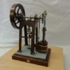
 25215 forum posts 3105 photos 1 articles | As neil likes the "church font" I showed the other day that it would be nice to do a bit or ornamental turning and add a couple of candle stick holders to go with it.
Mostly turned with 1.0m and 2.2mm insert parting tools and a 2mm dia MRMN grooving insert. the part you can see is 65mm high and 22mm dia at the base.
|
| JasonB | 05/08/2017 20:05:03 |
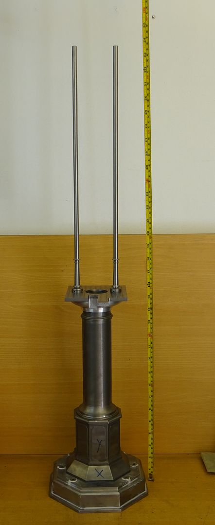
25215 forum posts 3105 photos 1 articles | Well with the guide rod bases done I could not resist the temptation to add the rods to see how tall the engine will end up. So chopped a couple of 430mm bits off a 1.0m length of 9mm silver steel and then turned and threaded the ends. Did someone recently say silver steel doe snot thread well with a die?
Looks about 34" tall to me. Quiet pleased as there is only a couple of thou difference between the crods top to bottom at the moment and once the top bar is in place that should be sorted
Edited By JasonB on 05/08/2017 20:05:56 |
| mechman48 | 06/08/2017 11:35:18 |
 2947 forum posts 468 photos | A bit more done on my version of the Vertical Cross engine to Stewart Hall's drawings. I didn't have any ally bar of 55mm dia. for the base, so marked out, drilled, tapped, & turned a piece of 10mm ally plate to required dimensions. The tapping mode gave me the chance to try out a 3mm spiral flute tap I picked up at a car boot fair some time ago as the tapped holes were shown as 5.5mm deep so not through holes, all tapped out nicely with cuttings coming up & out as designed to do. Must keep my eyes peeled for more spiral flute taps... |
| Jim Nic | 06/08/2017 13:49:42 |
 406 forum posts 235 photos | Hi George As I recall I drilled the cylinder and steam chest to drawing and luckily got it right. I do have a DRO on my mill/drill which makes that a better option for me than spotting through and picking up the marks. This part actually allows a little inaccuracy especially if you clad the cylinder Also I normally make clearance holes a tad big, normally 0.1mm, to give a bit of wriggleability. As Stew Hart (not Hall, he was the giggling fool off "It's a Knockout " from the telly wasn't he?) says "A little bit of clearance never got in the road." Jim |
| David Standing 1 | 06/08/2017 21:26:36 |
| 1297 forum posts 50 photos | As part of my ongoing machinery upgrade policy, A Myford 254S mysteriously founds its way into my workshop this week, to replace my Super 7. It was obtained via a dealer, and came out of a workshop that had gone into liquidation. Condition was as per it was dragged away from the operator, and he clearly didn't have time to clean it! it's actually in good condition, little wear in gibs and ways, and underneath all the grime there was quite a nice lathe struggling to get out. Above all, it was very cheap! It had been used for turning plastic as well as metal, and everything was spattered in a weird sticky plastic jelly type gunge. About six hours hard work with a big can of petrol, brushes and scrapers, and here's the before and after pictures:
|
| mechman48 | 08/08/2017 19:33:11 |
2947 forum posts 468 photos | Niiiice! looks like you got a bargain there, any extras included?
|
| mechman48 | 08/08/2017 20:25:49 |
2947 forum posts 468 photos | Bit more done on the Vert' cross ... drilling for valve chest studs, 1.6mm drill... DRO's certainly help with the hole spacing ... |
| David Standing 1 | 08/08/2017 22:01:42 |
| 1297 forum posts 50 photos | Posted by mechman48 on 08/08/2017 19:33:11:
Niiiice! looks like you got a bargain there, any extras included?
It also came with a 4 Jaw Pratt Burnerd chuck (looks pretty much unused), Albrecht keyless tailstock chuck, brand new genuine Myford operating manual (these are around £50), 4 QC toolholders, decent live centre. I paid £1,450 for the lot so I didn't think that was bad. |
| Roderick Jenkins | 08/08/2017 22:03:47 |
 2376 forum posts 800 photos | I'm having a go at George Thomas' bending rolls. Made the gears today, a stick of 20t 20DP. The gear cutter came from RDG, still sharp, no sign of any wear on the teeth.
Parted off, bored and tidied up in soft jaws in the lathe. Seeing as the mill was in horizontal mode I thought I'd use the slotting attachment to make the keyway in two of the gears.
I had to make the slot tooling, I've never used the slotting attachment before
Nice bit of kit but probably simpler and quicker to use the hand shaper for little slotting jobs like this.
Rod |
| Andrew Johnston | 08/08/2017 22:14:21 |
 7061 forum posts 719 photos | Lovely looking gears. Andrew |
| Roderick Jenkins | 08/08/2017 22:49:50 |
2376 forum posts 800 photos | Indeed it is. Presumably focussed on making Myford change gears. Free cutting mild steel - very flattering to average technique. |
| thaiguzzi | 09/08/2017 06:26:14 |
 704 forum posts 131 photos | That Sharp mill - horizontal, vertical AND slotting - nice bit of kit. |
| mechman48 | 09/08/2017 09:56:01 |
2947 forum posts 468 photos | Super bit of kit there Rod, like the set up for horizontal, vertical & slotting capability thaiguzzi says it's a 'Sharpe' any particular model? I'll nose around 'Lathes.co.uk' to have a look see details. Edited By mechman48 on 09/08/2017 10:13:35 |
| mechman48 | 10/08/2017 23:31:46 |
2947 forum posts 468 photos | Vertical Cross progress... tapped out valve chest for studding, machined up valve chest, drilled for studs, nice to have DRO's to help ... still managed to get one stud out of alignment, always seem to do that.... |
| Muzzer | 11/08/2017 10:47:57 |
 2904 forum posts 448 photos | Finally made some progress out in the workshop. Lost a lot of time recently due to 3 weeks in China (work), 2 weeks in Wales / Yorks (hols) and bringing the ceiling down (planned and almost controlled!) in the new kitchen / dining room, so there hasn't been much activity out there for a while. I also spent some time commissioning the stick, MIG and TIG welders, so I'm back in the welding game again. Previously I'd designed a tool setting fixture to hold my ISO40 ER40 collet chucks during tightening. There is no easy way to hold an ISO40 toolholder without damaging it, unless you have a suitable fixture. Tightening them in the spindle is not recommended and you could make a grand mess of your knuckles if you slipped when tightening a sharp new cutter. This was largely a CAD/CAM/CNC exercise, designed to progress a complete design from the PC into metal, using my (now largely finished) CNC milling machine. It's a 1983 Shizuoka that I have retrofitted with a 3-axis Chinese Fanuc clone controller. Although I've now got a fair bit of experience with 3D CAD, this was my first start-to-finish project using CNC. All in all it seems to have gone rather well - no obvious dimensional cockups, no broken tools and it bolted together nicely. The remaining component parts: Machine tapping with 100% thread in the manual mill:
In use:
So that's another one ticked off! Quite a few milestones passed on the way, so feeling quite fulfilled. Time for a couple of beers perhaps. Murray |
| Jim Nic | 11/08/2017 12:03:31 |
406 forum posts 235 photos | Vertical Cross coming along nicely George. As I remember Stew's design calls for the piston valve hole to be made all the way through the valve chest and a plug to be inserted to seal the bottom. I found I was able to drill and ream to within a couple of mm of the bottom and the valve still had room to operate and I avoided the need for a plug and the potential for an air (or steam) leak. Jim |
| Andrew Johnston | 11/08/2017 20:08:52 |
7061 forum posts 719 photos | Posted by Muzzer on 11/08/2017 10:47:57:
So that's another one ticked off! Quite a few milestones passed on the way, so feeling quite fulfilled. Time for a couple of beers perhaps. Never mind a couple of beers, I think that effort deserves the whole case. Very impressive, and no broken tools, way better than I managed. It must have been a sizeable task on it's own justgetting the mill going. Andrew |
| John Stevenson | 11/08/2017 21:51:54 |
 5068 forum posts 3 photos | Murray, when you bought that load off BT40. Tooling off me didn't you grab the bolt on fixture off the end of the CNC Beaver? Check your pm for one from me please |
| mechman48 | 13/08/2017 09:43:13 |
2947 forum posts 468 photos | Posted by Jim Nic on 11/08/2017 12:03:31:
Vertical Cross coming along nicely George. As I remember Stew's design calls for the piston valve hole to be made all the way through the valve chest and a plug to be inserted to seal the bottom. I found I was able to drill and ream to within a couple of mm of the bottom and the valve still had room to operate and I avoided the need for a plug and the potential for an air (or steam) leak. Jim
|
| Jim Nic | 13/08/2017 11:46:43 |
406 forum posts 235 photos | Hi George Here I come with advice a bit late again. I am still using carbon impregnated string as a seal medium so I use ordinary twist drills for stuffing boxes and leave the conical seat at the bottom of the hole after tapping and then the flat on the end of the gland follower tends to compress the string on to the shaft. Counterbores or such are not then necessary. Small O rings are the modern method I understand, so a flat bottomed hole will work just fine or just leave the drilled seat. Jim |


.jpg")


.jpg")


.jpg")


This thread is closed.
Magazine Locator
Want the latest issue of Model Engineer or Model Engineers' Workshop? Use our magazine locator links to find your nearest stockist!
Sign up to our Newsletter
Sign up to our newsletter and get a free digital issue.
You can unsubscribe at anytime. View our privacy policy at www.mortons.co.uk/privacy
Latest Forum Posts
- hemingway ball turner
04/07/2025 14:40:26 - *Oct 2023: FORUM MIGRATION TIMELINE*
05/10/2023 07:57:11 - Making ER11 collet chuck
05/10/2023 07:56:24 - What did you do today? 2023
05/10/2023 07:25:01 - Orrery
05/10/2023 06:00:41 - Wera hand-tools
05/10/2023 05:47:07 - New member
05/10/2023 04:40:11 - Problems with external pot on at1 vfd
05/10/2023 00:06:32 - Drain plug
04/10/2023 23:36:17 - digi phase converter for 10 machines.....
04/10/2023 23:13:48 - More Latest Posts...
- View All Topics
Support Our Partners


Shopping Partners
Subscription Offer

Latest "For Sale" Ads
- Reeves** - Rebuilt Royal Scot by Martin Evans
by John Broughton
£300.00 - BRITANNIA 5" GAUGE James Perrier
by Jon Seabright 1
£2,500.00 - Drill Grinder - for restoration
by Nigel Graham 2
£0.00 - WARCO WM18 MILLING MACHINE
by Alex Chudley
£1,200.00 - MYFORD SUPER 7 LATHE
by Alex Chudley
£2,000.00 - More "For Sale" Ads...
Latest "Wanted" Ads
- D1-3 backplate
by Michael Horley
Price Not Specified - fixed steady for a Colchester bantam mark1 800
by George Jervis
Price Not Specified - lbsc pansy
by JACK SIDEBOTHAM
Price Not Specified - Pratt Burnerd multifit chuck key.
by Tim Riome
Price Not Specified - BANDSAW BLADE WELDER
by HUGH
Price Not Specified - More "Wanted" Ads...
Get In Touch!
Do you want to contact the Model Engineer and Model Engineers' Workshop team?
You can contact us by phone, mail or email about the magazines including becoming a contributor, submitting reader's letters or making queries about articles. You can also get in touch about this website, advertising or other general issues.
Click THIS LINK for full contact details.
For subscription issues please see THIS LINK.
Digital Back Issues


Donate

 Register
 Log-in
Model Engineer Magazine
- Percival Marshall
- M.E. History
- LittleLEC
- M.E. Clock

ME Workshop
- An Adcock
- & Shipley
- Horizontal
- Mill

Subscribe Now
- Great savings
- Delivered to your door

Pre-order your copy!
- Delivered to your doorstep!
- Free UK delivery!
All Forum Topics > Work In Progress and completed items > The Workshop Progress Thread (2017)