Forum sponsored by:

Stuart 'No.1' : a beginners tale..
| Bob Brown 1 | 17/05/2014 15:53:46 |
 1022 forum posts 127 photos | Thrown into the pot are different grades, some common ones are M2, M35 and M42, the latter two being cobalt steel, 5% and 8% respectively. |
| JasonB | 17/05/2014 15:59:27 |
 25215 forum posts 3105 photos 1 articles | Here you go
View looking along the bar, hopefully you can see that I have cut the edge back at a radius so it does not run on teh hole below the centre line.
A view from above, the work is set to move away from the chuck eg towards the right.
Looking horizontally, you can see the slight top rake of the cutter which slopes down from the cutting edge
And an overall view, I will e-mail you a PDF of this which you can move about and zoom in on.
|
| GarryC | 17/05/2014 18:24:42 |
 740 forum posts 1043 photos | Jason A big thanks for these, the diagrams are excellent and make it very clear what needs to be done. I can see the one I did needs more work. I'll carry on with that and do another from scratch as per these diagrams as well. Hope this hasn't taken you too long to do - I'll bet though that lots of others like me will learn a lot from this.. and I must say it's definitely easier to understand a little better after having a go... I'll post up my next efforts... Allan and Bob Thanks, some more useful info there - and I will take a look on Youtube.. Regards. Allan. ps. Its obvious to see the enormous amount of help I've been getting on here but what isn't obvious is how much 'off forum' help has been offered as well, the enthusiasm from others has been incredible - just totally brilliant..! Anyone starting out and thinking of joining here - don't think twice do it now!
Edited By Allan. on 17/05/2014 18:28:01 |
| John Olsen | 17/05/2014 23:41:51 |
| 1294 forum posts 108 photos 1 articles | When you (not if!!) you have broken both ends of a small centre drill, remember to put it aside to make more boring cutters. It can save having to buy the HSS. Don't try to use the shank part of an ordinary drill, they are not hard. It can be pretty fiddly setting the cutter for the correct depth of cut. If the bar is drilled at an angle you can use a micrometer or at a pinch a digital or vernier caliper across the bar and the tip. You subtract half the diameter of the bar from the reading, then double to get the diameter it will cut. John |
| GarryC | 18/05/2014 10:45:53 |
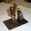
740 forum posts 1043 photos | Thanks John I did break one a few weeks backs now and threw it out! Hadn't thought about doing any future grinding then but will keep them in future. Yes I can see its going to be a bit fiddly adjusting the cuts but I imagine something that gets easier the more you times you do it - hope so anyway! Just had another go at grinding again trying to get close to Jason's drawings. Its been much harder trying to get a couple of decent photo's than it was to do the grinding - and i've failed miserably, the iPhone just not focussing down that close.. Anyways here is a couple of the photos that I'm hoping will show if its useable or not. I did two but they are pretty much exactly the same. Here is one of them.. 2nd attempt at grinding the tool for the between ctrs boring bar 1.
2nd attempt at grinding the tool for the between ctrs boring bar 2.
2nd attempt at grinding the tool for the between ctrs boring bar 3.
Regards Allan.
|
| JasonB | 18/05/2014 11:01:04 |
25215 forum posts 3105 photos 1 articles | Just as well I poped in from the workshop. To my eye the one you have done looks a bit pointy and if the cut surface was magnified would be very much line a fine pitch screw thread. If you look at the second sketch I did from above you should see that the front of the tool is about 10deg from a line taken across the lathe and likewise the side of teh tool about 10deg from a line along the lathes axis. When magnified this would give the impression of a much flatter series of Vees and result in a smoother bearing. Yoy can click all of these images to get them larger, I have added teh actual angles to this one I was just eyeballing them when I drew it so don't try to match them exactly its just to give an idea or what to aim for.
|
| GarryC | 18/05/2014 11:05:50 |
740 forum posts 1043 photos | Great thanks again Jason - I'm glad you were about! Back to the grinder now for another go.... Cheers. Allan. |
| Bob Brown 1 | 18/05/2014 11:10:36 |
1022 forum posts 127 photos | "Pointy" that's easy fixed just put a radius on the end. Bob |
| John Olsen | 18/05/2014 12:01:45 |
| 1294 forum posts 108 photos 1 articles | Yes, I would suggest just radiusing the tip by hand with an oilstone slip. If you don't have one yet, a piece of wet and dry paper glued onto a flat surface will do the trick. John |
| GarryC | 18/05/2014 12:48:43 |
740 forum posts 1043 photos | Hi Bob and John - I don't have an oilstone yet but am going to get one. Missed your 'radius' solution before going back to the workshop - but it was good to have another play on the grinder.. Jason, if you would take another look sometime I would be grateful. No probs if its not right and I need to try again.. Its photographing this one that is the real problem for me.. 3rd time lucky maybe? 3rd attempt at grinding the tool for the between cts boring bar 1
3rd attempt at grinding the tool for the between cts boring bar 2.
3rd attempt at grinding the tool for the between cts boring bar 3.
3rd attempt at grinding the tool for the between cts boring bar 4. Trying to show there is a slight top rake..
Regards Allan.
|
| JasonB | 18/05/2014 13:16:24 |
25215 forum posts 3105 photos 1 articles |
The only thing to watch with a radiused cutter is not to go too far, it can make the width of the material being cut wider annd result in chatter, on the end of a long boring bar or middle of a slender between ctrs one it can push the tall away from the surface more than an angular one that will cut in and take a small cut. Just a few strokes is OK but don't get carried away |
| GarryC | 18/05/2014 13:35:28 |
740 forum posts 1043 photos | Great thanks a lot Jason. For a minute back there I think I was in danger of having the only Stuart No.1 with a 'screw in' crankshaft! I hear what you say so I'll be taking tiny cuts! Cheers. Allan.
|
| GaryM | 18/05/2014 22:11:52 |
 314 forum posts 44 photos | Posted by Allan. on 18/05/2014 10:45:53:
............ Just had another go at grinding again trying to get close to Jason's drawings. Its been much harder trying to get a couple of decent photo's than it was to do the grinding - and i've failed miserably, the iPhone just not focussing down that close.. ............... Regards Allan.
Allan, When taking close-up shots on your phone, what might work better is taking them from slightly further away and then cropping the image down to the subject. Assuming you've got some software to do it. Just an idea. Gary |
| JasonB | 19/05/2014 07:26:45 |
25215 forum posts 3105 photos 1 articles | A couple of points about setting teh tool. I theory with a 3/8" bar and the tool sticking out 1/16" it will measure 0.4375 on the mic and produce a 1/2" hole. In practice the tip may not be exactly on the central axis, the bar may be running a fraction eccentric or have a slight bend/bow making it cut over or under the calculated size. So take some measurements of the bore you are produceing and work out how much more the tool needs to be advanced to arrive at the desired size. Its not easy measuring a small bore so find something a bit smaller than 1/2" either the shank of a 12mm cutter or a 15/32" drill and use that as a bore gauge. A bit of maths will then tell you how much to advance the too to get to teh crankshaft size but when you get close do test fit rather than just measure. On way to set the tool to a measurement is to have the grub screw just making the bit firm, push it out past where you want and then use the mic to gently squeeze it back into the bar, stopping when teh mic reads what you want the tool set at. J |
| GarryC | 19/05/2014 13:10:16 |
740 forum posts 1043 photos | Hi Gary Yes that sounds like a good idea, I'll give that a go next time, cheers - the combination of the small size and shiny steel was too much.. Hi Jason Thats really useful thanks, I'll keep all that in mind when doing it. I've been having some 'vague' thoughts about how best to adjust the tool - the method you mention sounds perfect to try.. In a strange way I'm glad now that I've had the problems with the bearings and took the 'time out' to do the boring bar as well - If not I would have missed out on what feels to be good experiences and learning in getting or at least trying to get them back on track - finding out about between ctrs boring and laying a bit of foundation for tool grinding to build on, issues with soldering together for drilling, problems and learning about working with Gunmetal, using slot mills for making holes etc.! To have missed out on all that would have been a big loss.. Can't wait to have a go with the bar, looks like Thurs will be good as I should have a complete free day to 'play'. Tomorrow I'm going to have a go at straightening out the hole in the 'bad' bearing to get to the same size as the other one (before desoldering both of them ready for the lathe) - I'll do that with a slot or maybe try an end mill this time - on the mill again (that reminds me I need to get some 6A fuses to go back in the mill).. I thought the 'wonky' hole was at 7.5mm but checking this morning its at 9.5mm. So I'll use a 10mm cutter, very slowly and carefully which should then allow the boring bar to fit through both bearings on the lathe... Cheers. Allan. |
| Nigel McBurney 1 | 19/05/2014 18:11:12 |
 1101 forum posts 3 photos | Setting a boring tool is difficult,one way to get over the problem is to bore the hole as close to size as you can,then turn the shaft to suit, or bore the hole to within a few thou and finish ream to size.When restoring stationary engines I always bore the cylinders and get a new piston cast and then turn it to fit the bore.When using a between centre boring bar first check the tailstock is in line with headstock,particularly if the tailstock has been set over for taper turning at some time,The between centre boring bar has the advantage that it bores a constant diameter,though a bore may be found to be tapered this can be is due to tool wear so when taking the final couple of cuts make sure the tool is sharp. In the past when this country did proper engineering long boring bars were mainly used on horizontal borers the tools held by wedges ,screws or taper pins,and the tools adjusted by a special depth micrometer mounted on a special vee block,the vee block was held on the boring bar and the amount the tool protruded from the bar measured by the micrometer, in more recent times adjustable tool holders could be screwed into the boring bars and a index ring provided micrometer adjustment and carbide insert used for cutting,they were very good but were limited to larger bores. |
| GarryC | 19/05/2014 20:34:24 |
740 forum posts 1043 photos | Hi Nigel Thanks for such an interesting post and some useful general methodology there. Before deciding to make one I was thinking about getting the boring bar kit from Hemingway **LINK** - it has perhaps a similar method of accurately measuring the tool adjustment as you were describing. I'm hoping to get on ok with the one I have made now though - not having made any kind of tool before it will be very satisfying if it does a good job... Cheers. Allan. |
| roy entwistle | 19/05/2014 20:45:40 |
| 1716 forum posts | Allan Just a point Is your tool steel HSS or is it Silver Steel ? If silver steel you can shape it with a file and it will need tempering I personally have not seen HSS in long lengths I may be wrong Roy |
| JasonB | 19/05/2014 20:49:22 |
25215 forum posts 3105 photos 1 articles | Roy its got HSS printed on the side, look at the first photo on Allans post 12.48 yesterday (wood grain background) Its only 1/8" dia so looks about 3" long which is quite common for HSS blanks |
| GarryC | 19/05/2014 21:18:55 |
740 forum posts 1043 photos | Roy and Jason Yes quite right it is HSS and about 3 inches long - from Tracey Tools. I didn't know there were different grades until Bob explained above, so I don't know how hard it will prove to be. I'll check the writing on it, maybe it will say which it is. The slightest touch on the smooth wheel of the Grinder was all that was needed - but then it is only 1/8 inch. I've not cut it to length yet.. Each 3 inch length was only £1 I think.. Cheers Allan. |


This thread is closed.
Magazine Locator
Want the latest issue of Model Engineer or Model Engineers' Workshop? Use our magazine locator links to find your nearest stockist!
Sign up to our Newsletter
Sign up to our newsletter and get a free digital issue.
You can unsubscribe at anytime. View our privacy policy at www.mortons.co.uk/privacy
Latest Forum Posts
- *Oct 2023: FORUM MIGRATION TIMELINE*
05/10/2023 07:57:11 - Making ER11 collet chuck
05/10/2023 07:56:24 - What did you do today? 2023
05/10/2023 07:25:01 - Orrery
05/10/2023 06:00:41 - Wera hand-tools
05/10/2023 05:47:07 - New member
05/10/2023 04:40:11 - Problems with external pot on at1 vfd
05/10/2023 00:06:32 - Drain plug
04/10/2023 23:36:17 - digi phase converter for 10 machines.....
04/10/2023 23:13:48 - Winter Storage Of Locomotives
04/10/2023 21:02:11 - More Latest Posts...
- View All Topics
Support Our Partners


Shopping Partners
Subscription Offer

Latest "For Sale" Ads
- Reeves** - Rebuilt Royal Scot by Martin Evans
by John Broughton
£300.00 - BRITANNIA 5" GAUGE James Perrier
by Jon Seabright 1
£2,500.00 - Drill Grinder - for restoration
by Nigel Graham 2
£0.00 - WARCO WM18 MILLING MACHINE
by Alex Chudley
£1,200.00 - MYFORD SUPER 7 LATHE
by Alex Chudley
£2,000.00 - More "For Sale" Ads...
Latest "Wanted" Ads
- D1-3 backplate
by Michael Horley
Price Not Specified - fixed steady for a Colchester bantam mark1 800
by George Jervis
Price Not Specified - lbsc pansy
by JACK SIDEBOTHAM
Price Not Specified - Pratt Burnerd multifit chuck key.
by Tim Riome
Price Not Specified - BANDSAW BLADE WELDER
by HUGH
Price Not Specified - More "Wanted" Ads...
Get In Touch!
Do you want to contact the Model Engineer and Model Engineers' Workshop team?
You can contact us by phone, mail or email about the magazines including becoming a contributor, submitting reader's letters or making queries about articles. You can also get in touch about this website, advertising or other general issues.
Click THIS LINK for full contact details.
For subscription issues please see THIS LINK.
Digital Back Issues


Donate

 Register
 Log-in
Model Engineer Magazine
- Percival Marshall
- M.E. History
- LittleLEC
- M.E. Clock

ME Workshop
- An Adcock
- & Shipley
- Horizontal
- Mill

Subscribe Now
- Great savings
- Delivered to your door

Pre-order your copy!
- Delivered to your doorstep!
- Free UK delivery!
All Forum Topics > Work In Progress and completed items > Stuart 'No.1' : a beginners tale..