Forum sponsored by:

Arduinos and Microcontrollers ref: Rotary Table Mew 249
| Neil Wyatt | 21/02/2017 18:36:50 |
 19226 forum posts 749 photos 86 articles | Ha! It seems : followed by S codes for that smiley! Neil |
| Bazyle | 21/02/2017 18:39:09 |
 6956 forum posts 229 photos | Dave, how about using the serial interface from the main programming pc which presumably is still available. Though many won't have the pc in the workshop I guess some do for other CNC & 3D printing. |
| Muzzer | 21/02/2017 20:15:17 |
 2904 forum posts 448 photos | Loads of Arduino (and other) stuff at DFRobot - delivery is quick and prices not bad. And CPC Farnell has a Maker brochure. I wish this stuff had been around when I was younger! Murray |
| John Stevenson | 21/02/2017 21:32:48 |
 5068 forum posts 3 photos | Posted by Carl Wilson 4 on 21/02/2017 12:48:02:
The whole point of the article was to show those with little or no electronics knowledge that systems such as the one covered are within anyone's grasp. It was intended to demonstrate that electronics and microcontrollers definitely have a place within the sphere of mechanical engineering, as they now have had in the real world for over 30 years. I hoped to show that anyone can use these modular systems to assemble a device in short order that can solve a production engineering problem as it arises. If I saved £1.50 in the process, so much the better. Carl. It's not about the £1.50, it's about building a better mouse trap. Indexers for most people are use occasionally devices and just have a couple of buttons and nested menu's and loads of clicks isn't something that stays locked in your mind.
From replies since I have posted it appears that I'm not the only one that thinks that way. All the hard work is done. The sketches are out there, it just needs someone to demonstrate that it is truly a modular system. |
| John Stevenson | 21/02/2017 21:40:53 |
5068 forum posts 3 photos | Posted by Bazyle on 21/02/2017 18:39:09:
Dave, how about using the serial interface from the main programming pc which presumably is still available. Though many won't have the pc in the workshop I guess some do for other CNC & 3D printing. Been done. Got the tee shirt. Looking back thru some files and pictures dated around November 2010 I found a system that I paid to have developed for British Nuclear Fuels, can't say what the job was or they would kill me but it did involve a £80,000 camera [ no typo ] and it had to work as it was in the hot side, and still is.
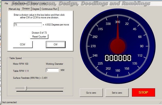
This is the simplified screen we used for testing.
Their system was far more complex and had a load of features we would never use and was integral to their software. This was very simple and worked well.
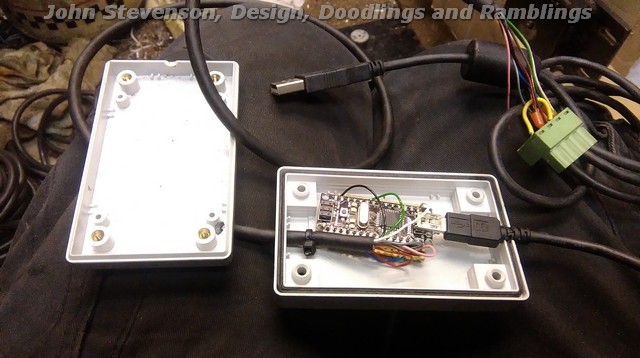
It took signals from the PC, via a USB lead to an Arduino UNO and in turn this spat out step and direction to a Leadshine stepper driver.
It only needs the USB in and 3 wires out Step +, Dir + and step and dir - The extra wires were for limits, remote start and stop etc.
Because I paid for this I still own the files and the rights to use it. |
| Carl Wilson 4 | 21/02/2017 23:03:35 |
 670 forum posts 53 photos | I have to say that looks very good indeed. |
| John Stevenson | 21/02/2017 23:30:27 |
5068 forum posts 3 photos | Posted by Carl Wilson 4 on 21/02/2017 23:03:35:
I have to say that looks very good indeed. It should do for what it cost
Seriously this was the test software which was just a spin off from BNF's job. Drawback to this is you are tied to a PC which is why I have never pushed it. It was more a reply to Bazyle asking about PC's. |
| David Taylor | 22/02/2017 01:11:39 |
 144 forum posts 39 photos | Posted by Muzzer on 05/12/2016 12:58:21:
Like most of our generation, I've been messing with micros for much of my career but the upcoming generation has been born into this wave of technology, which is so much more powerful, cost effective and user friendly than what we were used to. It's fascinating to think where this is leading...
I taught myself to program back in the early 80s, have always been interested in the lowest level operation of computers, and always worked as a programmer. And yet not one of my 4 children has shown the slightest inclination to look beyond watching youtube or playing games. I think their saturation in computers has the opposite effect - to me as a teenager they were new and interesting and thought-provoking. To today's kids they're like a washing machine, VCR, or DVR. There is no real wonder to it. There will always be people interested in them but I don't think we're ever going to raise a generation who consider coding a normal skill any more than we ever had a generation who could all do plumbing, or design rockets. I kind of disagree with the user-friendly part too. Writing programs on a BBC micro or Commodore 64 was a lot easier than all the hoops you have to jump through today, whether it be installing an IDE, running a python interpreter or whatever. There is more info about though, and its a lot easier to get it. |
| Zebethyal | 22/02/2017 07:16:36 |
| 198 forum posts | Posted by Emgee on 21/02/2017 16:05:07:
John S, Have you got a link please to the £1-50 keypad for the Arduino, i've seen keypads but not certain they can be used with the Arduino. Emgee Here is a link to some Chinese membrane keypads on The Bay, 2 for £0.99 and free shipping. These, and the press button ones, are simply a 4x4 matrix connected via 8 wires (4 across, 4 down). If you want a library for simple integration, there is one on the Arduino Playground, or you can write your own code to do the same thing (can make for smaller code, as you do not need to cater for different sized keypads). |
| Baldric | 22/02/2017 12:51:43 |
| 195 forum posts 32 photos | Posted by SillyOldDuffer on 21/02/2017 16:00:53:
Two, with a rotary digital encoder and a panel mounted joystick. The mode would be dialled up by turning the Mode switch. Then up, down, right, left and 'go' would be selected by moving and pressing the joystick. Labelling is easy and the switches could be protected inside a box.
Cheers, Dave I must admit I had been thinking along slightly different lines, the rotary being used to do the up/down, but also when in jog mode to actually do the movement. In run mode I had considered using a single axis joystick, but then wondered if a rotary, joystick and something to change mode was to many controls. As with so many things what can make a good application bad is the user interface. Baldric |
| Emgee | 22/02/2017 13:19:44 |
| 2610 forum posts 312 photos | Posted by Zebethyal on 22/02/2017 07:16:36:
These, and the press button ones, are simply a 4x4 matrix connected via 8 wires (4 across, 4 down). If you want a library for simple integration, there is one on the Arduino Playground, or you can write your own code to do the same thing (can make for smaller code, as you do not need to cater for different sized keypads). Thanks for the links but those keypads have a 7 pin socket, not 8. I was hoping to just have a plug and play keypad as I have no understanding of programming a sketch for Arduino. I see a 7 pin socket on the UNO and a further set of 9 upward facing pins adjacent to the socket, would the keypad connect to either of these ? Thanks, Emgee |
| Zebethyal | 22/02/2017 15:02:50 |
| 198 forum posts | Posted by Emgee on 22/02/2017 13:19:44:
Posted by Zebethyal on 22/02/2017 07:16:36:
These, and the press button ones, are simply a 4x4 matrix connected via 8 wires (4 across, 4 down). If you want a library for simple integration, there is one on the Arduino Playground, or you can write your own code to do the same thing (can make for smaller code, as you do not need to cater for different sized keypads). Thanks for the links but those keypads have a 7 pin socket, not 8. I was hoping to just have a plug and play keypad as I have no understanding of programming a sketch for Arduino. I see a 7 pin socket on the UNO and a further set of 9 upward facing pins adjacent to the socket, would the keypad connect to either of these ? Thanks, Emgee Just re-checked the picture on the Ebay listing I linked to - it definitely has an 8 pin connector. Most of the items marked as suitable for use with an Arduino are not plug and play, they are merely something mounted on a PCB, maybe with some extra electronics and a pin header to interface with it. The assumption is that someone is going to write a sketch to make use of it, or combine a number of libraries in a sketch if they don't feel like writing it all from scratch. I am sure you are aware that the Arduino is merely a microcontroller on a board with no intelligence other than what you upload via a compiled sketch to it - it is in effect a blank canvas. If you want to have, for example, an LED light up, it makes no difference to the Arduino if it is attached to pin 1, or pin 5, that is your choice, just so long as you tell it, in your scetch, which pin to send the voltage out of in order to light the LED. |
| JasonB | 22/02/2017 16:16:01 |
 25215 forum posts 3105 photos 1 articles | The one in your link is a 4x3 matrix so 7 pin socket Similar 4x4 pads do have 8 pins such as this |
| SillyOldDuffer | 22/02/2017 21:55:08 |
| 10668 forum posts 2415 photos | Posted by Baldric on 22/02/2017 12:51:43:
Posted by SillyOldDuffer on 21/02/2017 16:00:53:
Two, with a rotary digital encoder and a panel mounted joystick. The mode would be dialled up by turning the Mode switch. Then up, down, right, left and 'go' would be selected by moving and pressing the joystick. Labelling is easy and the switches could be protected inside a box.
...
I must admit I had been thinking along slightly different lines, the rotary being used to do the up/down, but also when in jog mode to actually do the movement. In run mode I had considered using a single axis joystick, but then wondered if a rotary, joystick and something to change mode was to many controls. As with so many things what can make a good application bad is the user interface. Baldric Hi Baldric, Not much progress as I've been diverted on to parent sitting; my mum is just out of hospital. I hadn't thought of using the switches as you describe, but it is logical! Just goes to show why interfaces are difficult to design. We all expect things to work our way. I was going to jog by pressing the joystick, but the rotary encoder has a press switch too. At the moment I'm tendiing towards a matrix keypad with the option to control it with a serial interface as suggested by Bazyle as well. It wouldn't be difficult to do away with the physical USB connection with a Bluetooth wifi module and put a graphical interface on a tablet. A big advantage of a keypad is that mode-select can be done with a single keypress. My first step has been to check there are enough spare pins on the Arduino. 8, 9, 4, 5, 6, 7 and 10 are used by the DF Robot; 2, 3, 11, A0, A1 and A2 are used to control the motor and for temperature sensing; 0 and 1 are the serial interface. This leaves 5 spare pins (12, 13, A3, A4 and A5) when 7 are needed for a 4x4 keypad. An Arduino Mega has plenty of spare pins but gosh, they're about £10! So I think I'll dump the temperature sensors and repurpose A1 and A2. Next step is to separate the motor drive code from the existing key button functions; at the moment they are interleaved. Then I can apply different control interfaces to work the motor. As an armchair project, it's going rather well. There will be tears when I start coding and reality bites me! Dave |
| Frank.N Storm | 22/02/2017 22:07:02 |
| 50 forum posts 1 photos | Although I'm not building a motorised rotary table, I'm experimenting with stepper motors and Arduinos at the moment. So I did read this thread with much interest. I have to admit I was a bit shocked when I checked the links given by J.Swift on the 7/2. One TB6560 driver for £ 11.99! Without knowing this thread (and because I fried the driver I used before) I ordered a couple of drivers via Ebay, and among them I got two such drivers for $ 9.90, postage free. And now, Mr. Costa: the Chinese are not stupid, and they know about VAT taxes etc. in Europe. On that famous customs slip they stated (in that case) "Electronic parts, value $ 3.00" . Not that it would make a difference, as in my country values below around £ 50.00 are not taxed - the expenses would cost more than the tax. I really don't think that anywhere in Europe imports in one-digit values are taxed - if I'm wrong, how many cents/pennies then? So, don't be afraid of ordering in China - but naturally it won't be in your letterbox tomorrow. Regards, Frank |
| Zebethyal | 23/02/2017 07:12:32 |
| 198 forum posts | Posted by JasonB on 22/02/2017 16:16:01:
The one in your link is a 4x3 matrix so 7 pin socket Similar 4x4 pads do have 8 pins such as this My mistake - I meant to link to this one here, same price of £0.99 for 2 but 4x4 matrix. |
| SillyOldDuffer | 16/03/2017 14:42:24 |
| 10668 forum posts 2415 photos | For anyone interested the latest update to my keypad based indexer and a pdf to read are at this Dropbox Link Using a cheap matrix key pad like this:
It provides the same functions as the Gary Liming's program, but has been extended in various ways. (Mainly the ability to type in numbers, PAUSE, REWIND and control via the USB port.)
The display uses the DFRobot, though it's push buttons are ignored. It is not difficult to substitute a cheaper 1602 display only board or an I2C display. In this example, Bump is selected with 10 steps clockwise. Pressing '*' jogs the motor. A Bump too far may be undone by pressing '1' to REWIND it, which is handy.
When the motor is running a progress countdown is displayed. If you try this please report any bugs. Although there's been lots of testing it's amazing how the bleeding obvious still slips through! The pdf includes more examples and the wiring diagram. Dave
|
| Centurian | 29/07/2017 07:05:01 |
 10 forum posts 2 photos | I've built a driver for my turntable exactly as specified in the article and cross checked with Gary Limings articles. My problem is that when I power it on it works as advertised to the point where it displays the correct startup screen I.E Select Mode, Mode = Step. If I press Select nothing happens. Pressing Left scrolls through the Modes. Pressing Up also scrolls through the modes and Down Scrolls through the modes in the reverse direction. Pressing the "Right" button does nothing. Pressing reset does a reset and also switches off the run light on the stepper driver module. At all times whilst power is applied the actual stepper motor is locked. I have tried another display module and also a different processor module. ( an Arduino Mega) I have also tried it with no stepper driver connected. all I get is the above. Does any one have a clue what I'm doing wrong? I have been very careful in my wiring and anyway I have tried it with just the Arduino Uno and display shield. |
| SillyOldDuffer | 29/07/2017 09:53:22 |
| 10668 forum posts 2415 photos | Posted by Centurian on 29/07/2017 07:05:01:
Select Mode, Mode = Step. If I press Select nothing happens. Pressing Left scrolls through the Modes. Pressing Up also scrolls through the modes and Down Scrolls through the modes in the reverse direction. Pressing the "Right" button does nothing. Pressing reset does a reset and also switches off the run light on the stepper driver module. Does any one have a clue what I'm doing wrong? I have been very careful in my wiring and anyway I have tried it with just the Arduino Uno and display shield. Hi Centurion, This sounds like a well known problem that was discussed earlier on this thread. See my post on Page 4 and John Swift on page 8. Those buttons are not individual switches. Instead, they cause a voltage change when pressed. The Arduino measures the voltage and decides which button has been pushed. Your problem is probably down to a small difference between the various versions of the Display Board. (Apart from there being a Mk1 and a Mk2, there are plenty of clones.) To fix it all you have to do is alter a few numbers in the Arduino Sketch to match your particular display board. The code is the six 'if (Key_in ... )' statements right at the end of Gary's sketch. It looks like this: int read_LCD_button() // routine to read the LCD's buttons if (key_in > 850) return NO_KEY; } Note Gary Liming's comment // average values for my board were: 0, 144, 324, 505, 742 In the example above are the key_in values I used. (850, 70, 250, 450, 650, 850) You might try those values first. If that fails, download this sketch and temporarily install it instead of Gary's program. All the sketch does is display the actual number generated by your keys. Write them down, then change the key_in values in Gary's sketch as per his +100 comment and re-install it. With luck all should now be well. Dave |
| Centurian | 29/07/2017 11:25:08 |
10 forum posts 2 photos | Thanks I followed your advice and download the "test" sketch and using the numbers obtained modyfied the 2.3 sketch. All now works according to Hoyle. Many thanks for your response. I thought I'd checked all the relevent threads, but you know what they say about thought. |


Please login to post a reply.
Magazine Locator
Want the latest issue of Model Engineer or Model Engineers' Workshop? Use our magazine locator links to find your nearest stockist!
Sign up to our Newsletter
Sign up to our newsletter and get a free digital issue.
You can unsubscribe at anytime. View our privacy policy at www.mortons.co.uk/privacy
Latest Forum Posts
- hemingway ball turner
04/07/2025 14:40:26 - *Oct 2023: FORUM MIGRATION TIMELINE*
05/10/2023 07:57:11 - Making ER11 collet chuck
05/10/2023 07:56:24 - What did you do today? 2023
05/10/2023 07:25:01 - Orrery
05/10/2023 06:00:41 - Wera hand-tools
05/10/2023 05:47:07 - New member
05/10/2023 04:40:11 - Problems with external pot on at1 vfd
05/10/2023 00:06:32 - Drain plug
04/10/2023 23:36:17 - digi phase converter for 10 machines.....
04/10/2023 23:13:48 - More Latest Posts...
- View All Topics
Support Our Partners


Shopping Partners
Subscription Offer

Latest "For Sale" Ads
- Reeves** - Rebuilt Royal Scot by Martin Evans
by John Broughton
£300.00 - BRITANNIA 5" GAUGE James Perrier
by Jon Seabright 1
£2,500.00 - Drill Grinder - for restoration
by Nigel Graham 2
£0.00 - WARCO WM18 MILLING MACHINE
by Alex Chudley
£1,200.00 - MYFORD SUPER 7 LATHE
by Alex Chudley
£2,000.00 - More "For Sale" Ads...
Latest "Wanted" Ads
- D1-3 backplate
by Michael Horley
Price Not Specified - fixed steady for a Colchester bantam mark1 800
by George Jervis
Price Not Specified - lbsc pansy
by JACK SIDEBOTHAM
Price Not Specified - Pratt Burnerd multifit chuck key.
by Tim Riome
Price Not Specified - BANDSAW BLADE WELDER
by HUGH
Price Not Specified - More "Wanted" Ads...
Get In Touch!
Do you want to contact the Model Engineer and Model Engineers' Workshop team?
You can contact us by phone, mail or email about the magazines including becoming a contributor, submitting reader's letters or making queries about articles. You can also get in touch about this website, advertising or other general issues.
Click THIS LINK for full contact details.
For subscription issues please see THIS LINK.
Digital Back Issues


Donate

 Register
 Log-in
Model Engineer Magazine
- Percival Marshall
- M.E. History
- LittleLEC
- M.E. Clock

ME Workshop
- An Adcock
- & Shipley
- Horizontal
- Mill

Subscribe Now
- Great savings
- Delivered to your door

Pre-order your copy!
- Delivered to your doorstep!
- Free UK delivery!
All Forum Topics > Electronics in the Workshop > Arduinos and Microcontrollers ref: Rotary Table Mew 249