Member postings for John McNamara
Here is a list of all the postings John McNamara has made in our forums. Click on a thread name to jump to the thread.
| Thread: Which books |
| 16/08/2018 00:58:47 |
To learn lathework. milling Welding etc from a professional Abom79 on Youtube is a very good starting point, Most of the work he does is industrial so rather large but the same rules apply to the small workshop. |
| Thread: Facing Error |
| 16/08/2018 00:40:38 |
Hmm Back to basics..... Headstock spindle are the bearings tight with no play? Not much error there. Do another test facing cut. Edited By John McNamara on 16/08/2018 00:41:47 |
| Thread: Shingle bells |
| 18/07/2018 07:55:28 |
HI All It was the fact that there is a preventative measure available, a measure that I was unaware of and have paid for over the last 4 weeks which prompted me to post. Useful information that in my view should be passed on. If my post offended you by intruding into the workshop space please accept my apologies and ignore the information. Edited By John McNamara on 18/07/2018 07:57:53 |
| Thread: What depth concrete base for a workshop extension? |
| 17/07/2018 15:11:55 |
Hi CB |
| Thread: Shingle bells |
| 17/07/2018 10:01:11 |
Hi All The annoying bit is it may have been avoidable. there is a vaccine, ask the doc next time you visit. |
| Thread: Eccentric's "Turnado" |
| 17/07/2018 04:46:12 |
Every time i see one of Garry's new tools i am inspired by the attention to the detail and the many accessories, on this one right down to the finger grips on the tool body. Also the way the center point can be offset to completely turn a ball caught my eye. first class job. J Edited By John McNamara on 17/07/2018 04:47:33 |
| Thread: What depth concrete base for a workshop extension? |
| 16/07/2018 14:14:32 |
Hi CB The design of a slab and its edge and cross beams is determined by the type of soil it sits on. and the weight of the building it must support, however building weight is not normally the problem if single story. Soil stability is. Scalpings, sand, crushed rock etc will allow leveling a site but will not really help if the soil underneath them is low grade I know this sounds like a lot of effort but we spend many many ours in our shed, It must be right. (I am not a soil Engineer) I do however work with them as I did on site this morning discussing how to tackle an extension to an 1880 Victorian dwelling, yes the Victorians built attractive buildings however they knew very little about footings, as the often seen cracks prove. I see this time and again, Its a wonder they stay up, and it creates a lot of problems when modifying them. Regards Edited By John McNamara on 16/07/2018 14:15:06 |
| Thread: Looking for lathe mandrel test bars. |
| 16/07/2018 10:38:13 |
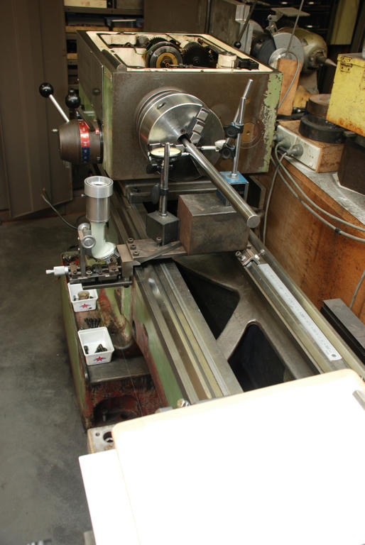
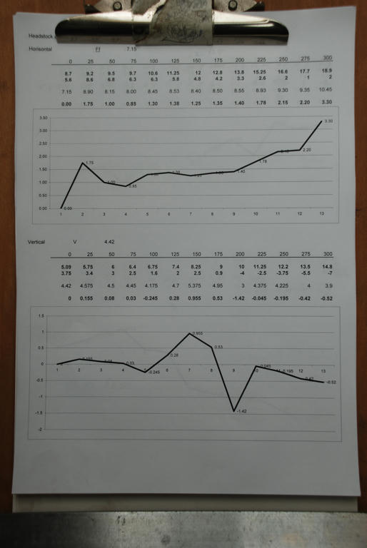
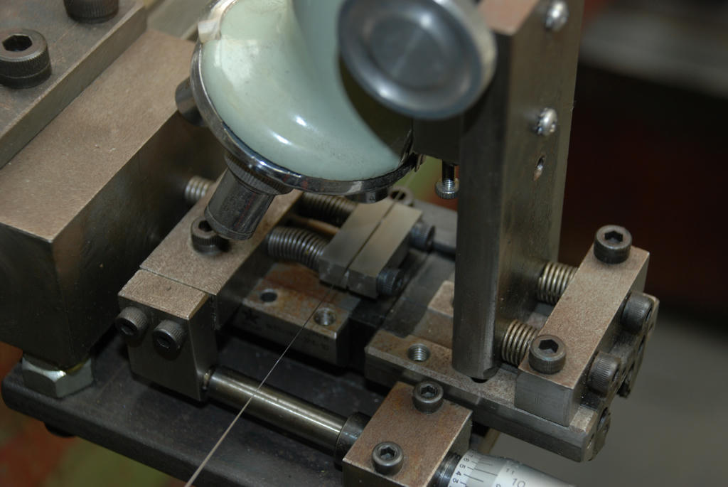
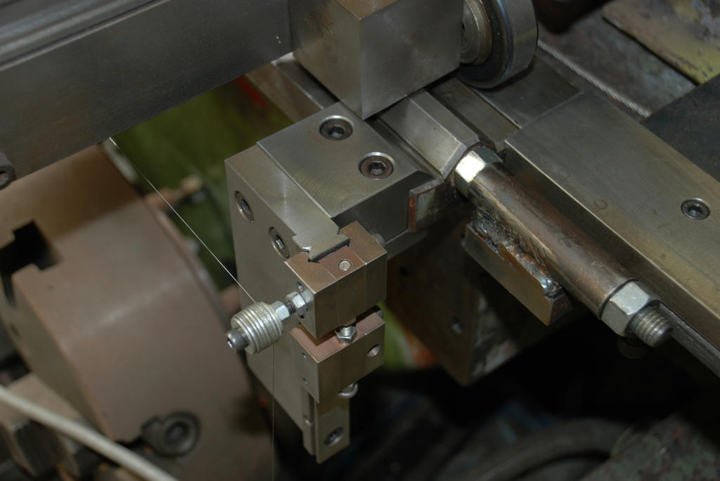
Hi Andrew Hi All Lathe Accuracy measurement. I restored my lathe about 2011, At the time I was thinking on how to align the spindle and came up with the method I mentioned previously. As you can see below I used two dial indicators and a 25mm ground steel bar to check the spindle axis of my lathe. I had had not studied Rollie's method as I thought it related to twisted beds, a case of GMTA. If I had seen this paper recently written I would have tried it instead of the microcope The CERN Accelerator is to this day mainly aligned by wire. Images: Also a couple of images of a wire mounting point, there were 2, one at each end of the bed and the microscope stage kludged up from scrap and a 50 power student microscope, nothing hardened! just scrap It worked well. I don't have measurements it was done on the fly the v groves were just milled. It was however rock solid and sturdy. once adjusted the whole jig was clamped tight that is important. Oh and a tenth accuracy Mitutoyo microscope head and a linear bearing formed the measuring stage that had to position the grove on center before a measurement was taken. The lathe bed was subsequently ground in situ, It worked well and I use the lathe to to this day, is it perfect? no, but almost. I do have a write up but too many pages to post here. Regards
|
| 15/07/2018 02:42:30 |
Hi All 25 – 40mm is ideal, of constant diameter say to Just set the bar up in your chuck a 3 will do but After cantering one point unless you are very lucky We are going to take several measurements along After setting up your dial indicator on the saddle and You will also need a ruler or other means to move Rule off rule off a piece of paper it will need 4 Now we are ready to find if there is any alignment Before starting check again that the tip of your Then rotate the spindle until the indicator reads Repeat this for all the other positions. At this point you have all the other highs and lows, Alternatively the result will describe a curve this If you can use Excel you can do all this on a This method does not check the alignment of the This method is a very good indicator of the To speed this process up fewer measuring points Regards |
| Thread: Last Night's Astro Image |
| 25/06/2018 08:58:50 |
Hi Neil I find it amazing, I will put you in contact with the fellow stargazer If you like. Regards
Edited By John McNamara on 25/06/2018 09:00:13 |
| Thread: Ideal amateur lathe spindle nose? |
| 18/06/2018 08:08:05 |
Hi Niels Having used a lathe with a screwed spindle nose for a number of years, I acquired a new for me lathe with a DIN 5507 nose with a bayonet ring at the back. I would never go back to a screwed nose. I think the bayonet fitting is a better mount than a Camlock nose, Camlock's sometimes work loose. Both Camlock and DIN 5507 use the same short taper. The only difference is nutted studs versus camlock pins. Making up a new back plate is not that hard. Link to types and sizes. Regards |
| Thread: Help with TurboCad Architectural |
| 18/06/2018 07:38:20 |
Hi John Olson Use bring to front. Regards
|
| Thread: Machinery's Handbook |
| 16/06/2018 02:00:05 |
Hi All |
| Thread: Designing for laser cutting in mild steel |
| 02/06/2018 06:34:18 |
Water jet works well however it has a few of caveats. The kerf of the cut is a lot wider than a laser particularly on thin materials under 10mm when compared to a laser, it is a little less accurate. Water jets can also cut steel 50mm thick or when pushed at a cost up to 75mm thick. I have read of 300mm cuts in steel. That may be an old record! In Melbourne at least where I live water jet is quite a lot more expensive. Accuracy: Apart from the physical limitations to accuracy, comparing laser cutters to water jet cutters there is the machine programmer and machine operator to consider. Highly accurate cutting requires the machines to be operated at the optimum speed for accuracy, this will be less than the optimum machine speed for production. You should discuss this with the cutting service provider if extreme accuracy is required. It may be an extra charge. To put .1mm into perspective If I make a rectangular hole in 5mm plate say 20.1mm x 5.1mm and make a tennon on the edge of a plate 5mm x 20mm then most of the time I will get a drop in fit. There will be a tiny radius on internal corners. This can be overcome by drawing in small relief areas not necessary for me I just touch them up with a tiny file. To a modern laser 5mm - 12mm plate cuts like butter. As plates get thicker the accuracy reduces slightly. Normally I will have multiple tenons on an edge fitting into into multiple rectangular holes for bolting or welding Every time I do it I am amazed! They all fit.... When getting a job quoted your job will cost less if you provide a clean DXF file for your part. If your CAD can draw closed polylines use them for all plat outlines and holes. Make sure lines are not elevated above zero if your program can do 3D. If just using lines make sure that every line end touches the next line exactly. Closed polylines make this easier. No line should have a loose end when making a hole. Edited By John McNamara on 02/06/2018 06:50:49 |
| 01/06/2018 13:38:34 |
The old rule of thumb is the hole should not be smaller than the material thickness, As I said the old rule. These days newer machines can make smaller holes than the material thickness. Fiber lasers in particular and the latest CO2 machines. Ask your cutting service what they can achieve. |
| Thread: Source of good HSS lathe tool blanks |
| 31/05/2018 12:52:22 |
I have a 4 way tool post on my lathe, two of the stations are fitted with two eccentric engineering tangential holders one fitted with a high speed steel bit the other I made from medium carbon steel with a carbide tip l brazed on by me. In both cases I find that the quality of your tool grind finish is very important. Since I switched to a fine diamond cup wheel that gives a mirror finish my work finish has improved and the time between regrinds greatly increased. I still find that HSS with a razor sharp mirror grind beats carbide almost every time for finishing to size, it allows you to shave down to a tenth or so where carbide will simply rub. The carbide tip works well with harder materials that HSS will not cut and for high speed metal removal that would burn HSS. I made my own grinder **LINK** however any grinder that can be fitted with a table that can be angled and a diamond cup wheel will do. |
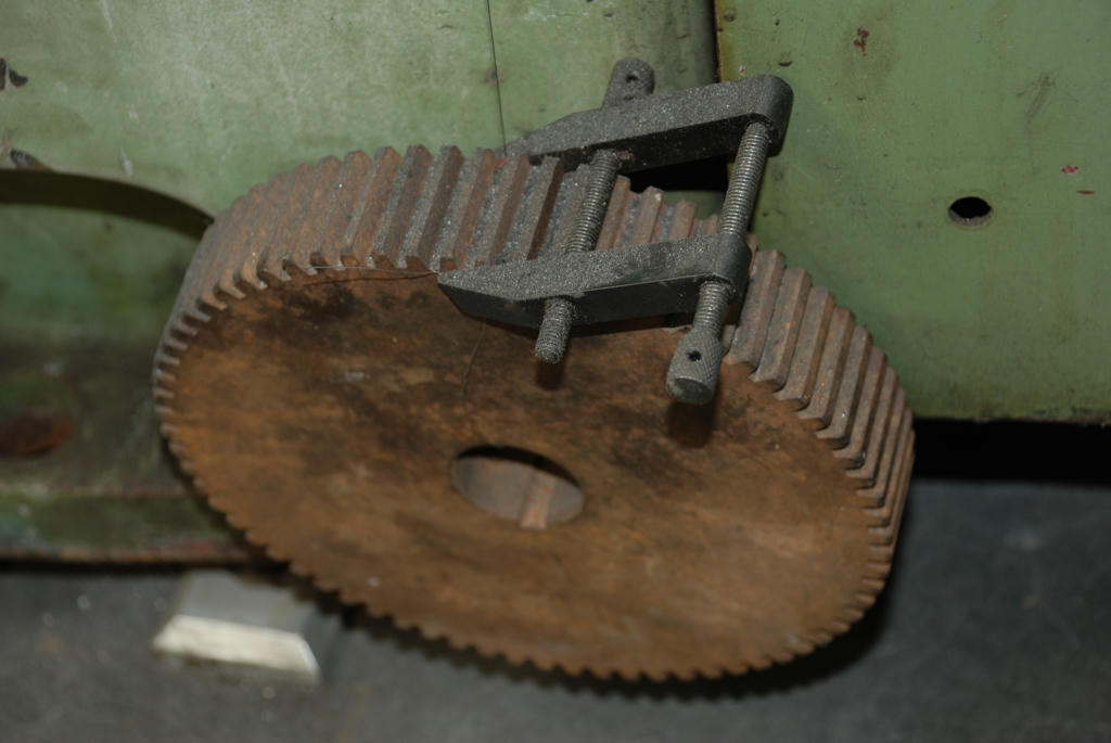
| Thread: Yet another what is it |
| 11/05/2018 14:48:52 |
I think the angled sides are a clue. Maybe a jig for grinding facets on some sort of cutting tool? Edited By John McNamara on 11/05/2018 14:49:20 |
| Thread: drilling a 20mmx 300mm Hole in cast iron |
| 10/05/2018 06:30:44 |
This week I had to drill axially centred 1mm x 70mm holes in some cast iron scrap bar. (window weights) It machined easily so all good. Well almost when I drilled it axially the drill wandered a bit maybe 20 thou, something had deflected the drill. hard spot, soft spot, who knows? In this case it was Ok as I was able to machine the outside of the bar after I had drilled it using the hole as a center hole. It was not a super precise job. I had used a normal jobber drill, and it had got the wanders This is where Gun drills differ, they often only have 1 cutting lip the rest of the drill is a solid cylinder several diameters long that has almost no clearance. fully supporting the cutting tip apart from a chip clearing groove. They usually have a cutting oil hole pressure fed to clear the chips, The tight fit in the hole helps keep them straight, think of a gun barrel maybe thirty inches long with a .177" finished hole with little or no straightening required, pretty amazing. Regards
|
| 10/05/2018 00:00:16 |
Yet again James Virgil Howe to the rescue There is a whole chapter on making gun drills, Regards Edited By John McNamara on 10/05/2018 00:01:27 |
| Thread: Would you like to own EVERY SINGLE Model Engineer edition ever published? |
| 26/04/2018 00:36:01 |
Hi Editor Neil |

Magazine Locator
Want the latest issue of Model Engineer or Model Engineers' Workshop? Use our magazine locator links to find your nearest stockist!
Sign up to our Newsletter
Sign up to our newsletter and get a free digital issue.
You can unsubscribe at anytime. View our privacy policy at www.mortons.co.uk/privacy
Latest Forum Posts
- hemingway ball turner
04/07/2025 14:40:26 - *Oct 2023: FORUM MIGRATION TIMELINE*
05/10/2023 07:57:11 - Making ER11 collet chuck
05/10/2023 07:56:24 - What did you do today? 2023
05/10/2023 07:25:01 - Orrery
05/10/2023 06:00:41 - Wera hand-tools
05/10/2023 05:47:07 - New member
05/10/2023 04:40:11 - Problems with external pot on at1 vfd
05/10/2023 00:06:32 - Drain plug
04/10/2023 23:36:17 - digi phase converter for 10 machines.....
04/10/2023 23:13:48 - More Latest Posts...
- View All Topics
Support Our Partners


Shopping Partners
Subscription Offer

Latest "For Sale" Ads
- Reeves** - Rebuilt Royal Scot by Martin Evans
by John Broughton
£300.00 - BRITANNIA 5" GAUGE James Perrier
by Jon Seabright 1
£2,500.00 - Drill Grinder - for restoration
by Nigel Graham 2
£0.00 - WARCO WM18 MILLING MACHINE
by Alex Chudley
£1,200.00 - MYFORD SUPER 7 LATHE
by Alex Chudley
£2,000.00 - More "For Sale" Ads...
Latest "Wanted" Ads
- D1-3 backplate
by Michael Horley
Price Not Specified - fixed steady for a Colchester bantam mark1 800
by George Jervis
Price Not Specified - lbsc pansy
by JACK SIDEBOTHAM
Price Not Specified - Pratt Burnerd multifit chuck key.
by Tim Riome
Price Not Specified - BANDSAW BLADE WELDER
by HUGH
Price Not Specified - More "Wanted" Ads...
Get In Touch!
Do you want to contact the Model Engineer and Model Engineers' Workshop team?
You can contact us by phone, mail or email about the magazines including becoming a contributor, submitting reader's letters or making queries about articles. You can also get in touch about this website, advertising or other general issues.
Click THIS LINK for full contact details.
For subscription issues please see THIS LINK.
Digital Back Issues


Donate

 Register
 Log-in
Model Engineer Magazine
- Percival Marshall
- M.E. History
- LittleLEC
- M.E. Clock

ME Workshop
- An Adcock
- & Shipley
- Horizontal
- Mill

Subscribe Now
- Great savings
- Delivered to your door

Pre-order your copy!
- Delivered to your doorstep!
- Free UK delivery!