Member postings for Sam Stones
Here is a list of all the postings Sam Stones has made in our forums. Click on a thread name to jump to the thread.
| Thread: Junk or what? |
| 04/04/2011 07:03:11 |
Perhaps OT, but does anyone have any ideas what it could be?
There are no prizes, I'm on a pension.
Sam
 First Clue - It was laying at the roadside. |
| Thread: Machining Strange materials |
| 03/04/2011 03:17:28 |
Hi Richard,
Please have a look at the thread titled Graphite Bushes. Go down to my posting date/time 19/07/2010 06:42:51
I mention the problem I had with glass-bead filled plastic material, when beads found their way under and jammed the ML7 saddle.
I can imagine the problems if the material was in any way magnetic.
Good luck,
Sam
|
| Thread: Suggestions please. |
| 03/04/2011 00:14:36 |
Hi,
It looks like I missed the boat on a couple of issues. Putting the clocks back last night, may have had something to do with it!!! I’m quite intrigued by all this (extra) detail about aspect ratios, picture cells, spherical aberrations, and so on, and I fully agree about the difficulty in setting up. Despite my longtime association with photography, setting up a camera is certainly not easy. All I can comment on here (although already mentioned) is, in setting up a camera, use the longest focal length macro lens you have available. However, scanning does seem to have greater set-up merit. One thought I had Graham (but now too late), was about scanning two images of the tool bit, 90 degrees to each other. The other relates to my own attempts to measure the angle of the previous image via Adobe Photoshop CS3 and my CAD package Keycreator. Although I measured an angle greater than 29 degrees, the image contrast on the lower side of the tool bit was not sufficient to obtain an accurate alignment. This was due to the shadow on the underside of the image. In CS3, adjusting contrast and what Adobe refer to as `Sharpen’ - `Unsharp Mask’ is readily achievable. However, although I tweaked the image, and in combination with the staircase (ragged) edges, there was still not sufficient `separation’ to accurately show how much greater than 29 degrees, the image was suggesting. I have to accept that being placed on the flat bed of a scanner, my previous comments about tilt, don’t figure. To digress a little, several years ago, it became necessary for me to determine the profile of a circular flume which was part of a moderately-sized casting, ie. about the size of the bell-housing around a typical car engine clutch. The casting, (which was shaped in such a way that measurements were very difficult to determine), had been hand poured and moulded in black polyester resin. In a geometric sense, the flume (channel) progressively decreased in depth radially as a means of distributing high velocity water evenly through the entire 360 degrees. I needed a low cost method to transfer various details of the moulding into CAD, and which could then be used to design a shape which could be injection moulded. Rather than resort to finding someone with a digitiser, I chose the following approach. A number of sections were cut around the flume, and were duly `cleaned up and flattened’ with a wood plane. Because parts of the moulding curved away to one side, this part of the sectioned piece became included in the scan. And, being in black material, it proved impossible to obtain a clear outline. Therefore, to increase the contrast, I simply painted the cut edge with white-out. Any excess white-out which had gone over the edge was cleaned away thus improving the edge detail. This thread has turned out to be most interesting. Well done Graham!!! Regards to All, Sam |
| 01/04/2011 21:23:36 |
Hi Graham,
Thanks for alloting me some credit wrt my `jig'. It's very flattering.
 Here's another clue about what seems to be happening (with respect to the efforts of others).
Isn’t there a risk that the posted photograph of the tool bit is very slightly skewed away from the camera? Even if the camera is near perfect, the top face of the tool bit must be perpendicular to the lens axis. Any tilt front to back, will increase the `optically’ measured angle, and therefore why it is that using the photograph (and CAD), is showing values greater than 29 degrees.
Of course, any sideways tilt will reduce the CAD-determined reading.
Regards to all,
Sam Edited By Sam Stones on 01/04/2011 21:44:32 |
| 31/03/2011 01:08:15 |
 Hi Graham, While you were fast asleep last night, I was hard at work cobbling out an interpretation of your smart method. Should anyone wonder what the blazes we were talking about in the distant future, they can view my renderings with jaw-dropping awe.
If you are someone who has just tuned in, the steel rules are clamped together through their (already existing) holes.
I must close for now, it's almost lunch time here in Melbourne, and not a pot washed.
Best regards to all,
Sam Edited By Sam Stones on 31/03/2011 01:09:35 |
| 30/03/2011 20:52:46 |
Hi Graham,
Your `twin rule' solution is a very neat idea, and puts more sense into my bit of geometry.
I'm sure it will prove useful to others, especially if shown with a 3D picture.
Thanks for your closing comment.
Best regards,
Sam
|
| 30/03/2011 00:33:21 |
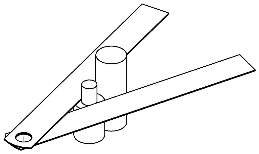
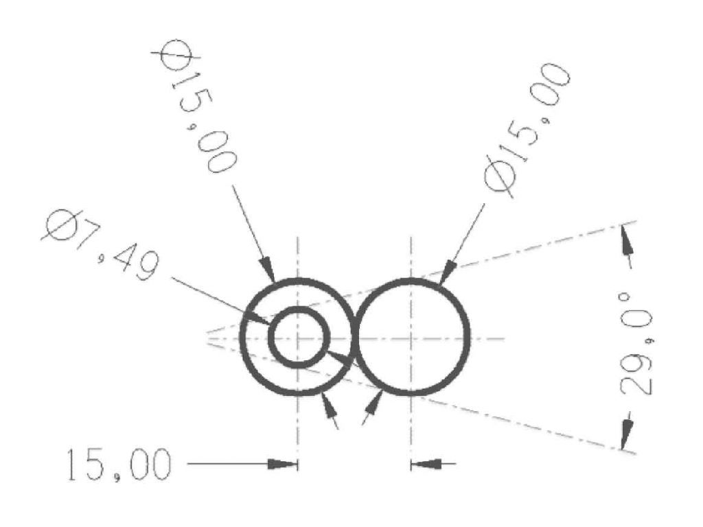 Hi Graham, For when you get home tonight, here's another version based upon your two-roller idea.
In this case, the rollers are identical in diameter and placed together. The end of one is stepped down to 7.49mm, and your two straight edges are placed tangentially as shown.
Holding them together will not be as neat compared with drilling holes in a plate, but . . .
Thanks for helping me in the recent past.
Best regards,
Sam |
| 29/03/2011 05:28:29 |
Hi Graham,
Although the optics may not be perfect, do you have access to an old slide projector? You could examine its potential as the starting point for a shadowgraph.
In my case, I'm able to turn to a couple of toolmaker friends who might possess a professional shadowgraph. Then of course, there are the technical colleges who may perhaps provide some help.
Regards,
Sam
|
| Thread: Amateurs |
| 24/03/2011 05:58:13 |
| Hi Donald,
In all seriousness, thank you for your initial posting, it has led to some very entertaining rhetoric.
Against your name I notice that it says: "This member does not have a public profile".
While we mere amateurs wait for pictures of your work, why not fill in the public profile too? |
| Thread: Models take all forms |
| 11/03/2011 06:32:24 |
|
Hi Graham,
What a coincidence!
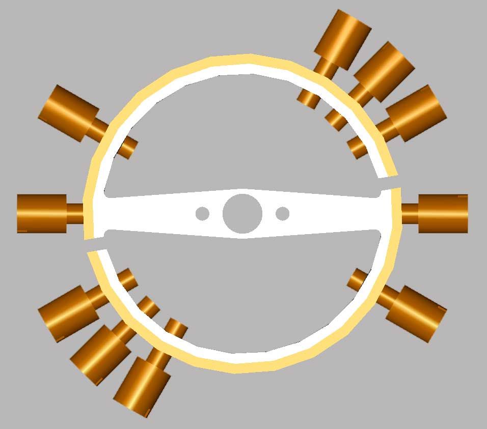
With three to go, I’m just about through my thirty-nine daily treatments for prostate cancer on one of these `Varion' intensity modulated radiation machines (see IMRT via the Internet).
I’m surprised to see that the beam is conical. I thought it was fully collimated.
Nice model-making too.
Sam
Edited By Sam Stones on 11/03/2011 06:33:32 |
| Thread: Strange angle ? |
| 10/03/2011 04:43:56 |
David Clark 1 wrote -
Not the end of the story. In some parts of the county it is called Mystic.
Not sure of exact spelling.
That's what we called it in my part of Lancashire, ie. Bolton.
A more technical name was soluble oil, and we had two sorts. One for general lathe and milling (machine) work, the other with a nicer smell, was for grinding.
Like David, I'm not sure if it was mystic or mistic (mist-stick). In grinding, it certainly became a mist.
Sorry to be so far OT, Eddie!!!
To climb back OT a little, my Myford ML7 had a top slide which could be indexed in an angular sense for taper turning. Does that mean it was a compound slide?
Sam |
| Thread: Taper reaming |
| 02/03/2011 06:07:48 |
To add to Ian's comment about turning the reamer in a clock-wise direction. As with any (fluted) reamer, never reverse the direction of rotation of a reamer as you do when tapping a hole.
Also, having turned several sprue bushes for plastics injection moulds, keeping the reamer in line via the tailstock was automatic. However, if you are hand reaming, you may need some form of steady or pilot to ensure proper reamer alignment.
Back in the 50's, we made our own HSS taper reamers. The taper was often an odd angle, as a result of the non-standard mould geometry. On one particular occasion, it was my job to make the initial turned blank. This was then fluted by one of the milling machine operators before it was hardened and finally ground to size.
The trouble emerged when it was discovered that the milling machine operator had cut the flutes in reverse. There wasn't enough time to make a new blank, and eventually, I had the job of reaming the (one-off) sprue bush with the lathe running backwards.
You may think that it would have been an easy task, except for the fact that I was still an apprentice working on a much neglected lathe, and, the lathe was driven from an overhead counter-shaft, via flat pulleys, ie. NO REVERSE.
The solution was that we crossed the secondary belt, while keeping a very close eye on the possibility that the lathe chuck could unscrew at any moment.
Fun days!!!
Sam
Edited By Sam Stones on 02/03/2011 06:10:56 Edited By Sam Stones on 02/03/2011 06:13:42 |
| Thread: Lathe motor popping |
| 02/03/2011 05:36:22 |
|
Thanks Phil.
Good luck with your 3PH conversion.
Curiously, over a period of several years (before I bought the lathe), I had on occasion to walk past the previous owner’s house. Over that time, I had actually seen the belt guard of the ML7 hanging from the picture rail of his upstairs box-room workshop. However, I had no idea what piece of machinery could be operating without a belt guard. Furthermore, I could never have realised that one day I would become the proud owner of his Myford. Besides the issue of seeing the belt guard hanging from the picture rail, the centrifugal switch may have been stuck open for a considerable time, because the previous owner had worn off a substantial amount of paint from the rim of the large pulley, and introduced a sort of polished patina to its edges. Sam Edited By Sam Stones on 02/03/2011 05:38:22 |
| 01/03/2011 21:23:36 |
|
Hi Phil, The Crompton & Parkinson 1/4 hp single phase motor fitted to my Myford ML7 used to do the same. In my case, (and because the motor was uncovered), metal swarf was finding its way into the electrics via the motor’s ventilation holes. The shorting was not sufficient to blow fuses or trip the leaky earth switch, but it certainly made a loud popping noise when it happened. There was also a sizzling noise (mechanical not electrical), which once again was swarf. This time the swarf was rubbing against the rotor. I would guess that steel swarf was being attracted to various parts as a result of the magnetic field(s). I cured this problem by applying metal fly wire (readily available in Australia), over the vents. The original lathe owner had a `wonderful’ way of starting the lathe. When I bought it from his widow, the centrifugal switch inside the motor was stuck in the `open’ position. It was clear that the owner (who had removed the belt guard), was using the large pulley to spin-start the lathe motor. Once the motor was stripped down, it took very little to free the switch.
Both problems were duly fixed and never returned.
I no longer have my workshop, but fitting a 3PH motor seems to be a very common improvement. See other postings. Best regards to all, Sam Edited By Sam Stones on 01/03/2011 21:26:52 |
| Thread: Some thoughts on Model Engineering |
| 26/02/2011 05:47:46 |
|
We could easily step into deeper water when referring to Americanisms.
Their engineers drive railway engines, don’t they? |
| Thread: Case Hardening |
| 02/02/2011 00:55:52 |
|
To temper or not to temper case-hardened mild steel, is a very interesting question mgj.
Surely it will not only depend upon the shape and thickness distribution of the part, but also upon its purpose? A solid lump of MS will no doubt be less likely to fail, than a part with varying thickness. I certainly wouldn’t venture into case-hardening a part whose reliability was important, without seriously considering the need for tempering.
Having replaced certain instrument parts which varied in thickness, and choosing to go via the case-hardened mild steel route, the question of final brittleness was always a consideration. I tend to view the case (skin?) of a case-hardened (even nitrided) part as being a little like a pie crust, which will craze and even collapse under external stresses. So, for the sake of an extra bit of safety, would you chance it?
Regards,
Sam |
| 21/01/2011 05:53:56 |
|
I fully support John Fawcett’s comments about cyanide heat treatment. It can be full of hazzards for both professionals and amateurs, as the following example shows. The `hardening shop’ I hinted at in my earlier posting on this subject, was a small room next door to our toolroom. It was accessed through a personal door in one corner of the toolroom. As a young apprentice, I could never comprehend that next door to the hardening shop was a fairly large work area know as the drug-store. It must have been the most significant fire risk area of the whole factory, since it was stocked with open bins of finely powdered coal, sulphur, and various other industrial chemicals. These chemicals were openly weighed into bins, which in turn were elevated along conveyors. There were bails of natural rubber too, ready to be cut up and fed to two-roll mills and large Banbury mixers. Back in the hardening shop were a couple of gas-heated cyanide baths measuring some 18" deep by about 9" diameter. There was also a small electric furnace for hardening HSS. I think it was normally heated to about 1250-1300C. For quenching, there was a bath of hot water, and standing on the floor was a rather large tank of oil which measured about 4' high and 4' diameter. Allowing for the volume of any items to be quenched, the oil tank was kept topped up to within an inch or so of the rim. It became necessary to harden several cylindrical mould inserts. At a guess, these steel inserts measured about 14" long and 6" diameter. The actual mould cavity was by way of a hole down the centre of the inserts. This through-hole measured perhaps 1.7" diameter. In order to lower these inserts into the cyanide bath, the wise ones in charge made up a hook and had it bolted to the platform of one of those hand pumped stacker-trucks. The idea being that the mould inserts could be lifted from the cyanide bath and then lowered into the oil. Unfortunately, when it came time to quench the first heated insert, the stacker truck could not be pumped up high enough to lift the insert over the edge of the oil tank. It was therefore necessary to rapidly transfer the red-hot insert from the hook of the stacker truck to a steel wire hoist above the oil tank, the hoist in turn being secured to the steel roof truss. The hoist consisted of two pulleys around which were several turns of twisted wire. The transfer went well, and the insert was lifted up and over the edge of the bath of oil. Then the real drama began. The hoist hadn’t been used for many years, and as the insert was being lowered into the oil bath, the hoist wire spun around and jammed. This was a perfect situation for a massive fire because, with the red-hot insert half in and half out of the oil, ignition was almost instantaneous. Burning oil began to pour over the sides of the tank, and there was panic. Somehow, they managed to free the hoist and totally submerge the insert, but flames began to leap towards the roof, as sand and all sorts of other stuff was used to try to quell the blaze. Finally, the fire was brought under control. The drug-store didn’t ignite, and the excitement ended with a toolroom full of smoke and several red faces I think the remaining inserts were sent away to be hardened, and why Kasenit is my preference for case-hardening.
Regards,
Sam Edited By Sam Stones on 21/01/2011 06:00:01 |
| 18/01/2011 02:26:29 |
Anthony,
Not knowing the size of the mild steel (MS) part which you intend to case harden, it's difficult to ascertain what would be most appropriate.
That said, I feel sure that Stewart would have gone on to mention that you need to quench the part in clean water or oil after final `soaking' of the MS part in the case-hardening compound.
I've had plenty of good results using case-hardening compound. Was it called Kasenit? There was none of the mess associated with burning leather etc. Then again, the parts I made were relatively small
After `soaking', the newly formed high carbon `skin' needs to be hardened and tempered just like normal high carbon steel, eg. silver steel and gauge plate.
I found that it was unnecessary to remove the powdery coating of compound. This would fall away during the initial quench from cherry red, leaving a pleasing (to me at least) mid gray colour.
Just to add to this, the procedure being used when I began my toolmaking apprenticeship in 1950, involved carefully lowering the clean AND VERY DRY mild steel parts into a bath of molten cyanide, set at around 950 degrees C.
Failure to dry the parts properly could result in a violent reaction from the cyanide bath.
I'm not sure if the cyanide needed charging with extra carbon, since we had one chap who did all of the hardening himself.
However, I don't recommend this latter process for the home enthusiast for very obvious reasons.
Good luck.
Sam |
| Thread: A bi-metallic balance wheel |
| 10/01/2011 05:07:40 |
|
I had been wondering to what degree the bimetallic balance wheel would change its shape due to temperature.
Stripping the wheel down to its bare minimum, I first soaked it in boiling water, then took a photograph. This was repeated but using the fridge freezer to again soak the wheel.
Because of the small bulk of the wheel, and thus a fairly rapid return to room temperature, I estimate that there would be about a 60 degree C temperature differential between the `warm’ and the `cold’ conditions. Also, please refer to my album "John Stevens Skeleton Clock" with the (much) greater number of pictures.
I wonder if this was worth the trouble.
Regards,
Sam
 A CAD image of the wheel.
The wheel at two temperatures.
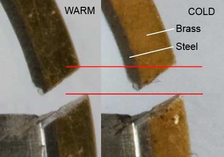 The change of shape is very slight. Will this be enough? |
| Thread: radius dresser |
| 08/01/2011 01:31:23 |
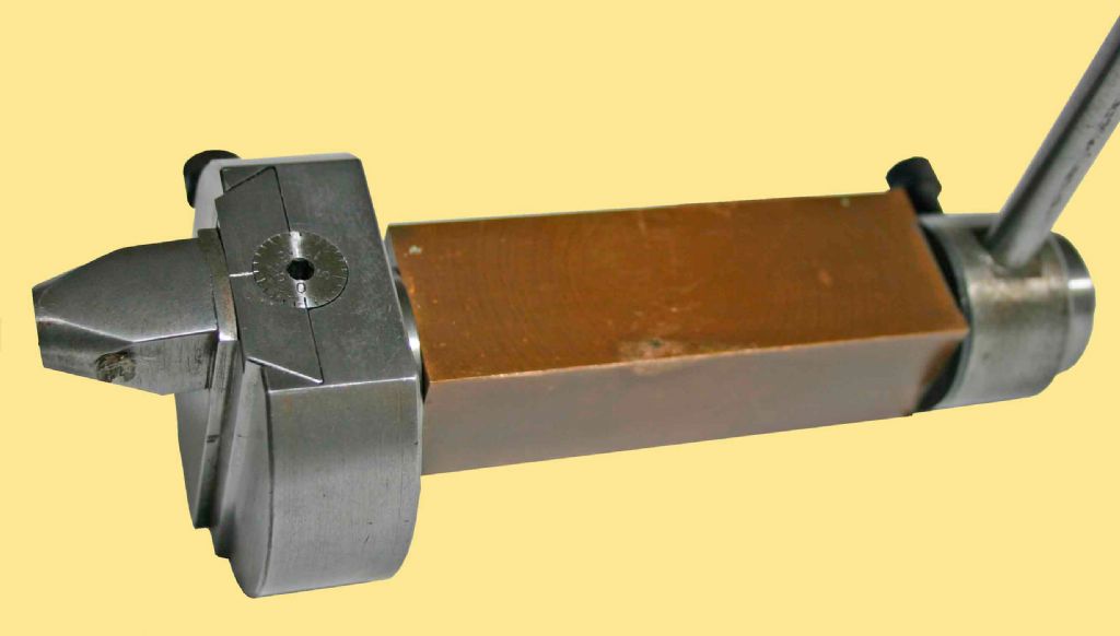 Hi Nobby, Perhaps a few words about the spherical turning attachment which I hinted at earlier. This version works in a totally different sense, with the cutter (a short length of round HSS), inserted into the end of the nose piece on the left of the image. The cutter is inclined downwards at about 5 degrees to provide `front’ clearance, while the protruding squared-off tip of the cutter is the `top’ cutting face. In other words, the main cutting force would tend to push the cutter further into the nose piece. Setting up requires that the axis of the device (holding the bronze bit in the tool post), is horizontal and exactly in the same plane as the horizontal axis of the lathe. The device axis should also be parallel with the cross slide movement. Using the cross slide, the tip of the cutter is then brought into line with the vertical axis of the workpiece so that when the device is rotated with the lever, the swept arc will generate a sphere. Bingo! As you can see, the dovetailed slide has a calibrated dial to adjust the depth of cut. I used a 40TPI thread for the tiny lead-screw, ie. 0.025" per revolution. The slide could be locked in place (finger tight) with the Allan screw just visible behind.
Although I didn't use the device other than to generate spheres, by raising it to a higher level in the tool post, a radius could be generated similar to that found on the outside of hand-wheels.
I trust this will be of interest.
Best regards,
Sam |
 .
.Magazine Locator
Want the latest issue of Model Engineer or Model Engineers' Workshop? Use our magazine locator links to find your nearest stockist!
Sign up to our Newsletter
Sign up to our newsletter and get a free digital issue.
You can unsubscribe at anytime. View our privacy policy at www.mortons.co.uk/privacy
Latest Forum Posts
- hemingway ball turner
04/07/2025 14:40:26 - *Oct 2023: FORUM MIGRATION TIMELINE*
05/10/2023 07:57:11 - Making ER11 collet chuck
05/10/2023 07:56:24 - What did you do today? 2023
05/10/2023 07:25:01 - Orrery
05/10/2023 06:00:41 - Wera hand-tools
05/10/2023 05:47:07 - New member
05/10/2023 04:40:11 - Problems with external pot on at1 vfd
05/10/2023 00:06:32 - Drain plug
04/10/2023 23:36:17 - digi phase converter for 10 machines.....
04/10/2023 23:13:48 - More Latest Posts...
- View All Topics
Support Our Partners


Shopping Partners
Subscription Offer

Latest "For Sale" Ads
- Reeves** - Rebuilt Royal Scot by Martin Evans
by John Broughton
£300.00 - BRITANNIA 5" GAUGE James Perrier
by Jon Seabright 1
£2,500.00 - Drill Grinder - for restoration
by Nigel Graham 2
£0.00 - WARCO WM18 MILLING MACHINE
by Alex Chudley
£1,200.00 - MYFORD SUPER 7 LATHE
by Alex Chudley
£2,000.00 - More "For Sale" Ads...
Latest "Wanted" Ads
- D1-3 backplate
by Michael Horley
Price Not Specified - fixed steady for a Colchester bantam mark1 800
by George Jervis
Price Not Specified - lbsc pansy
by JACK SIDEBOTHAM
Price Not Specified - Pratt Burnerd multifit chuck key.
by Tim Riome
Price Not Specified - BANDSAW BLADE WELDER
by HUGH
Price Not Specified - More "Wanted" Ads...
Get In Touch!
Do you want to contact the Model Engineer and Model Engineers' Workshop team?
You can contact us by phone, mail or email about the magazines including becoming a contributor, submitting reader's letters or making queries about articles. You can also get in touch about this website, advertising or other general issues.
Click THIS LINK for full contact details.
For subscription issues please see THIS LINK.
Digital Back Issues


Donate

 Register
 Log-in
Model Engineer Magazine
- Percival Marshall
- M.E. History
- LittleLEC
- M.E. Clock

ME Workshop
- An Adcock
- & Shipley
- Horizontal
- Mill

Subscribe Now
- Great savings
- Delivered to your door

Pre-order your copy!
- Delivered to your doorstep!
- Free UK delivery!