Member postings for Andy_G
Here is a list of all the postings Andy_G has made in our forums. Click on a thread name to jump to the thread.
| Thread: Tony Seba’s Prediction |
| 25/07/2023 01:07:42 |
Posted by Paul Kemp on 24/07/2023 21:50:40:
Average consumption per house per year (BEIS 2022) is 3,731 kWh (10.22kWh per day if there is still 365 days in a year). Personally I find that quite low but I have no idea proportion of flats to houses and no inclination to seek it out so let’s go with 10.22 kWh with no other “evidence” available
Average usage of 'medium' usage households is ~8kWh per day (link) making Mark Rand's comment even more far-fetched. About 25% of cars in England are parked on the street overnight - that's a lot of trailing leads. About 35% of UK homes have nowhere to park even a single vehicle, rising to 56% in London. (link) It isn't going to happen. (edit for unintended smilies) Edited By Andy_G on 25/07/2023 01:10:08 |
| Thread: Multiple Bearings in Spindle |
| 24/07/2023 00:21:27 |
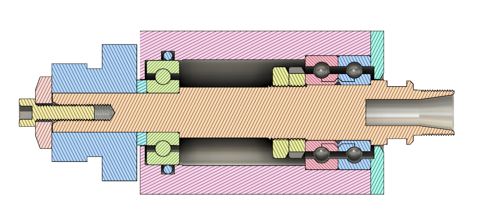
Are you concerned about stiffness? (Of the spindle!) For best stiffness, the front and rear bearings should be separated by 3-3.5 x the diameter of the shaft through the front bearings (so 24 to 28mm in this case - see page 66 of the SKF document I linked to earlier). The major contributors to the lack of stiffness of my original CNC spindle were the large tool overhang combined with an excessive distance between the spindle bearings, allowing the spindle shaft to flex between them. I try and explain in this video (from about 12:45 if it doesn't go straight there).
For my improved spindle, I also considered (and rejected) a spacer sleeve to clamp both front and rear bearings to the spindle at the same time. I wasn't convinced that I could make the sleeve to fit well enough that it was guaranteed to: a) run concentrically; b) Not bind up on the shaft; and c) end up perfectly parallel so that it didn't induce a bend in the spindle shaft when everything was clamped up. Edited By Andy_G on 24/07/2023 00:30:35 |
| Thread: Uncertainty of Measurement |
| 22/07/2023 22:10:00 |
There is 8% uncertainty in cross sectional area from the diameter measurements... Can you check density using the Archimedes principle? (Weight in air vs weight in water) You would probably need access to a 4DP balance - N.B. don't assume that the density of water is 1g/cm^3 - it isn't when trying to work to these accuracies. Anyway, on a separate note, Pure Pt *is* wetted by molten glasses. There is a specific, non-wetting alloy that is Pt5%Au. |
| Thread: Multiple Bearings in Spindle |
| 22/07/2023 21:48:33 |
As Howard said, the SKF literature is well worth a read. 'Design Considerations' from page 57 onwards: I went through what seems to be a similar thought process when trying to design a decent ER11 spindle for my CNC, but ended up with the arrancement below, that could be pre-assembled to the shaft before inserting into the housing: (I rejected designs based on ER11 collet extensions, as they resulted in a greater than necessary tool overhang.)
The nose bearings are a pair of matched A/C bearings from China.
I was very pleased with the outcome - about 4µm runout on the tool shank.
More words and pictures here:
|
| Thread: Lathe spindle alignment |
| 11/06/2023 11:30:59 |
Posted by Iain Downs on 11/06/2023 10:43:32:
. Did you check the trueness of the lathe after the work? I see that you'd checked that it was the same after bolting as before, but that assumes that the bed was in true to start with. That's something I will have to consider, probably later as I don't have the stock for that and my welding skills are ... dubious! Yes - I knew it was turning parallel before I started, so didn’t want to alter anything too much. It’s within about 0.01 mm over 100mm so I’m not inclined to mess with it. I wouldn’t bother with welding - just get hold of a length of rectangular hollow section steel - I only resorted to welding to use what I had around. |
| 10/06/2023 23:59:37 |
Posted by Iain Downs on 10/06/2023 21:06:22:
The lathe is rather small and is not secured to the bench. There's no particular way of doing that - not straightforwardly anyway. I also have a CJ18A 7X14 lathe (from Amadeal). Tweaking the headstock bolts shouldn't do anything if it is properly bolted down. You can easily correct that level of error by shimming the mounting 'feet'. (You can easily induce a much greater error, too!) The lathe can be secured from below, using the tapped mounting holes for the rubber feet. I used a length of rectangular hollow steel and filed / sanded it until it contacted all 4 feet. A piece of 0.0015" shim under one foot was needed to true it up. If you are interested, I described the process (and its effect) here: (The parting off at the end was very tentative because of previous problems that I'd had - I would go a lot quicker now!) Edited By Andy_G on 11/06/2023 00:09:49 |
| Thread: Hoglet - how hard to build? |
| 09/06/2023 09:05:50 |
There is also an excellent series of videos by Andrew Whale on Youtube that document his Hoglet build:
|
| Thread: Holding pipe when anodising?? |
| 21/05/2023 19:53:07 |
Posted by Engine Doctor ( Phil ) on 21/05/2023 10:48:55:
Nobody has mentioned using a de-smut dip prior to anodising bath. Not sure of acid content but it disolves any traces of other metals present in the surface of the alloy that will affect the finish . That is something I am interested in, but have never used. What problem does it solve? I have had a couple of odd results: Some sheet that displays a streaked pattern when anodised, but confined to the original surface - if you machine the surface, it disappears (this is dyed a pale yellow):
One of the chunks of alloy I have comes out a brassy yellow after anodising, despite the rest of the stuff being OK (From memory, the pieces on the left are H30/6082. The ring on the right is scrapbinium - all anodised together and not dyed.)
I this the sort of thing that de-smutting would address? (For 'known' alloys, the resuts are consistent). Edited By Andy_G on 21/05/2023 19:56:08 |
| 20/05/2023 23:43:28 |
Posted by Bevel on 20/05/2023 13:48:47:
Say for instance we take the tube I mentioned, do I need to calculate the whole surface area for outer and inner dia's? Also when doing multiple parts do I say calculate whole area for one then times by number I intend to do in one hit? Yes and yes I calculate based on 6mA per square cm which is near as dammit the same as 6A / square foot. I then use a constant current power supply to maintain this. For a protective coating, I find that 1 hour is enough, or 2 hours if the anodising will by dyed. (I think that this is the same basis as the '720' rule with 13µm or 25µm thickness respectively). I have a simple spreadsheet that I use to calculate simple parts as a combination of blocks, cylinders and discs, but it the part is drawn in CAD, I can get the surface area reported from it. Note that I quite often require >20 volts to maintain the required current. (This is with sodium bisulphate rather than sulphuric acid, but I don't think that should make any difference - the chemistry is the same.). A warmer bath needs less volts, but I've had rough looking coatings if the bath warms up too much. I don't bother with agitation, but then I'm not chasing any sort of specification. I clean the parts using fairy liquid and Scotchbrite under running tap water. I avoid them drying out between final cleaning and anodising by keeping them submerged in tap water. They have a quick dip in dilute sodium hydroxide (2% solution for 1-2 minutes - long enough for them to be covered in fine, white bubbles), then a rinse with DI water from a spray bottle, and into the anodising bath. They get another spray rinse when they come out, and I seal in almost boiling tap water for ~20 minutes. I have been pleasantly surprised by the predictability and consistency of the results. It's a lovely way to tidy up aluminium parts. |
| 20/05/2023 09:23:20 |
Anodising will work perfectly well on all surfaces in contact with the liquid, including the inside of a tube. (It's unlike electroplating in this respect.). One just needs to ensure that the bubbles generated during the process don't get trapped anywhere, as this will prevent those areas being anodised. I wouldn't put anything other than aluminium, titanium or lead in the anodising bath - definitely not steel. White spots will be where something has shielded the part from the bath for all or part of the process - a bubble, dirt, the point where the part is held, grease spots, etc. For a tube, provided I wasn't bothered about marks on the inside, I'd just bend some titanium / aluminium wire into a 'J' as above. For more stability, you can add multiple up/down bends to the tail of the J so there are several contact points inside the tube. "I still have my fingers crossed every time I do it" - do you work out the current required for each part to a consistent current density (amps per square inch / foot / mm / cm)? Do you use a constant current powersupply? |
| Thread: Bulkhead Penetrators (Getting a good vacuum seal) |
| 12/05/2023 13:26:21 |
You also need to pay attention to 'virtual leaks' if you aspire to high vacuum, or to maintaining a lower one without pumping: Essentially you need to avoid pockets where air can be trapped: Take for example the option of O-ring on the outside and clamping nut on the inside. The nut will form an imperfect seal with the inside of the chamber. While it probably isn't good enough to hold a vacuum, it slows down the rate at which the pocket of gas between the nut and the O-ring can escape. This will provide a steady stream of gas at low pressure until the pressure in the pocket equalises with the chamber. The preferred arrangement of the high vacuum chambers where I used to work was a flange with sealing O-ring inside the chamber with a stud through an over-sized hole secured with a nut and washer on the outside. The washers had holes drilled in them to connect the space around the stud to the outside air. I'm not sure that PVC is a good choice if you want to hold a vacuum (it will probably outgas and also allow gasses to diffuse through it). I second the suggestion to buy a surplus vacuum feedthrough. (The Apezion black wax is no less messy than araldite!) |
| Thread: Diesel heater recalls |
| 03/05/2023 20:26:26 |
Vevor diesel heaters were recalled in December last year following the seizure of almost 1000 of them at Felixtowe by Suffolk Trading Standards. I'd recently bought one from ebay and they (ebay) emailed me to tell me this and advised that I contact the vendor directly. I did this and received a refund and was asked to 'dispose of' the heater. I think that the Suffolk TS statement came out on some sort of social media, and can only find secondary references to it now.
"Consumers who believe they may have purchased an unsafe diesel heater are advised to stop using it immediately and report it to Trading Standards via Citizens Advice Consumer Service on 0808 223 1133."
Edited By Andy_G on 03/05/2023 20:28:02 |
| Thread: Major? Spindle play |
| 02/05/2023 14:17:53 |
Posted by Ady1 on 02/05/2023 10:36:13:
I haven't seen lathes or welders on Vevor UK for quite a while now I used to visit them regularly but gave up trying Edited By Ady1 on 02/05/2023 10:40:16 The customs & trading standards people have destroyed / blocked quite a few Vevor items: Office for Product Safety and Standards (No, I didn't know we had one, either.) |
| Thread: Warco WM-16 Motor Speed Fluctuation. |
| 26/04/2023 08:57:41 |
Posted by Ed Duffner on 22/04/2023 17:06:33:
...I have yet to test the speed potentiometer...
I would very strongly urge you to do that before doing anything else with the boards! As above - just replace it. They are 'wear parts' and don't last forever. |
| Thread: Is this a Warco / Metric thing...or am I just out of date? |
| 18/04/2023 21:19:10 |
Posted by Bo'sun on 18/04/2023 15:38:51:
What I am struggling with though, is the 0.04mm graduations. Odd graduations on the habdwheel dials drove me nuts when I first got my Chinese lathe - so much so that one of the first jobs was to make some new ones!
Edited By Andy_G on 18/04/2023 21:19:49 |
| Thread: 3018 CNC Router/digitizer/laser cutter modifications and upgrades |
| 06/04/2023 21:55:06 |
Thank you! |
| 06/04/2023 14:46:26 |
Posted by Russ B on 02/04/2023 21:20:05:
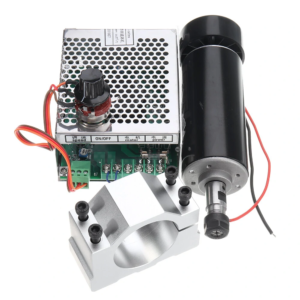
3.The spindle motor I can recommend steering clear of this style of spindle motor (ubiquitous on Amazon, Aliexpress, etc.) on grounds of both electrical safety and mechanical shortcomings.
My ultimately unsuccessful attempt to make a silk purse out of a sow's ear:
|
| Thread: Milling in the lathe |
| 04/04/2023 23:59:30 |
Posted by John McCulla on 04/04/2023 13:21:12:
I was wondering what is the best way to hold milling cutters in the lathe? It has MT4 taper at the headstock, so presumably I could buy a collet holder with a MT4 end, but would I need a drawbar extending through the headstock to hold it in? FInger collets are probably the cheapest option, but they don't seem to be readily available in MT4 as compared to MT2 or 3. So maybe a MT4-MT3 adapter (open type) and a few MT3 finger collets? Most of my end mills have 6mm or 10mm shanks, so that's only 2 finger collets - they're <£10 each from Arc. A drawbar is easy to make with a long bolt (or even threaded rod) and a turned collar to suit the rear of the spindle. Beware that the drawbar thread is usually different between metric and imperial collets (e.g. M12 vs 3/8 Whit). |
| Thread: Modifying the drive system of a cross-slide drilling attachment |
| 02/04/2023 19:19:30 |
I find this calculator very useful for timing belts as you can play with different pitches, etc. and it "knows" what the prefered tooth counts are.: https://www.bbman.com/belt-length-calculator/ I'd go for a poly-vee or similar belt for that application though. I struggled recently to find poly vee belts to suit short centre distances and found Megadyne 'TB2' section belts are available in much shorter lengths: LINK The design process is all in the technical manual: (PDF) For example: with an 83.6mm driving pulley, a 20mm driven pulley & a 345mm pitch length belt, you would retain the 85mm centre distance. The pulleys are fairly straightforward to machine (the profile details are in the PDF above) - you choose the number of ribs depending on the power to be transmitted.
Seem to work OK.
Edited By Andy_G on 02/04/2023 19:22:49 |
| Thread: Level/Flatness using laser/webcam/python |
| 01/04/2023 11:45:15 |
My tool guidance effort was a real-time servo system - no averaging. I was more successful with a profile measurement gauge that used a linescan camera illuminated by a LASER working over ~200mm. Sub-pixel resolution is easily possible through interpolation - similarly real-time edge detection from a video signal. Averaging will help remove random effects, but can't account for systematic errors. Hopefully it will get them what they want. When I dabbled in this professionally, anything like this was done in the 'Constant Temperature Room' which (as the name suggests) was maintained at a tightly controlled temperature 24/7 so you didn't get problems with thermal gradients due to temperature differences between equipment and the air. The beam divergence of LASER pointers is pretty poor.
|


Magazine Locator
Want the latest issue of Model Engineer or Model Engineers' Workshop? Use our magazine locator links to find your nearest stockist!
Sign up to our Newsletter
Sign up to our newsletter and get a free digital issue.
You can unsubscribe at anytime. View our privacy policy at www.mortons.co.uk/privacy
Latest Forum Posts
- *Oct 2023: FORUM MIGRATION TIMELINE*
05/10/2023 07:57:11 - Making ER11 collet chuck
05/10/2023 07:56:24 - What did you do today? 2023
05/10/2023 07:25:01 - Orrery
05/10/2023 06:00:41 - Wera hand-tools
05/10/2023 05:47:07 - New member
05/10/2023 04:40:11 - Problems with external pot on at1 vfd
05/10/2023 00:06:32 - Drain plug
04/10/2023 23:36:17 - digi phase converter for 10 machines.....
04/10/2023 23:13:48 - Winter Storage Of Locomotives
04/10/2023 21:02:11 - More Latest Posts...
- View All Topics
Support Our Partners


Shopping Partners
Subscription Offer

Latest "For Sale" Ads
- Reeves** - Rebuilt Royal Scot by Martin Evans
by John Broughton
£300.00 - BRITANNIA 5" GAUGE James Perrier
by Jon Seabright 1
£2,500.00 - Drill Grinder - for restoration
by Nigel Graham 2
£0.00 - WARCO WM18 MILLING MACHINE
by Alex Chudley
£1,200.00 - MYFORD SUPER 7 LATHE
by Alex Chudley
£2,000.00 - More "For Sale" Ads...
Latest "Wanted" Ads
- D1-3 backplate
by Michael Horley
Price Not Specified - fixed steady for a Colchester bantam mark1 800
by George Jervis
Price Not Specified - lbsc pansy
by JACK SIDEBOTHAM
Price Not Specified - Pratt Burnerd multifit chuck key.
by Tim Riome
Price Not Specified - BANDSAW BLADE WELDER
by HUGH
Price Not Specified - More "Wanted" Ads...
Get In Touch!
Do you want to contact the Model Engineer and Model Engineers' Workshop team?
You can contact us by phone, mail or email about the magazines including becoming a contributor, submitting reader's letters or making queries about articles. You can also get in touch about this website, advertising or other general issues.
Click THIS LINK for full contact details.
For subscription issues please see THIS LINK.
Digital Back Issues


Donate

 Register
 Log-in
Model Engineer Magazine
- Percival Marshall
- M.E. History
- LittleLEC
- M.E. Clock

ME Workshop
- An Adcock
- & Shipley
- Horizontal
- Mill

Subscribe Now
- Great savings
- Delivered to your door

Pre-order your copy!
- Delivered to your doorstep!
- Free UK delivery!