Forum sponsored by:

Multiple Bearings in Spindle
| Steve Crow | 20/07/2023 14:31:00 |
| 429 forum posts 268 photos | I want to make a small (20mm housing dia.) cartridge spindle for ER8 collets. I've got the Harprit Sandhu book and there are a few that I think I can miniaturise. I like the designs with 2 bearings up front. My question is, would there be much or any advantage to having 3 bearings up front? How about 2 at the back? I have to use quite puny (8mm x 14mm x 4mm) bearings due to space constraints so i'm hoping that stacking them up could help. Cheers Steve |
| Brian Wood | 20/07/2023 14:40:42 |
| 2742 forum posts 39 photos | Steve, I haven't checked but if you can get back to back taper roller bearings at the front end, that is where the loading on the spindle will be at its highest. The tail end is less important and a simple ball bearing there will be quite adequate. Regards Brian |
| HOWARDT | 20/07/2023 15:54:28 |
| 1081 forum posts 39 photos | Bearing design for a spindle depends on speed and forces. In my past life I drew designs for thousands of spindles, OK many of them were straight forward for vertical drilling operations but there were many in the five to ten thousand rpm range for more precision use and that is where things get interesting. SKF used to publish a design manual, I suspect you can still see it online, where they discussed different bearing arrangements for many uses. A lot of the older machines tools used these designs, which came first is any bodies guess. Commercially bearing manufacturers would work with designers to get the simplest bearing design, no point in sticking five bearings on a spindle is two would do. Following a known design of a spindle which fulfils you requirements is the simplest way but be careful that you follow all the parameters of the design. Using cheap bearings in a spindle which is required to run accurately at high speed will not work, or if it does not for long. Over lubricating can cause heat within the bearing and wreck everything , as will lack of proper lubrication. |
| Kiwi Bloke | 20/07/2023 22:36:01 |
| 912 forum posts 3 photos | As Howardt says, there's much to be found from bearing manufacturers, available online. Beware Harprit Sandhu's book. His double taper roller bearing design is OK. All the others are, in my opinion, seriously flawed. Working from memory, most are designed with the outer races abutting shoulders in the housing, and the inner races separated by a spacer tube over the shaft. This is fine, provided you can machine the relevant axial abutment dimensions accurately, but it makes the design non-adjustable, for fine-tuning of axial preload. It should be obvious that this is important when using angular-contact bearings, but it's also important when deep-groove bearings are used. I think there are some designs where axial location must rely on friction fits or adhesive. look critically, before cutting metal! The axial location of a spindle, and the axial stiffness of its bearings, is clearly of great importance. It's theoretically better for this to be taken care of by a pair of opposed bearings that are close together. If they are at either end of the spindle, its thermal expansion will alter the desired axial pre-load. Probably not a major problem for home machinists' spindles. If the bearing pair is at the 'business end', then you have two bearings sharing radial loads. Thus, designs tend to place bearing pairs at this end. In this case, the bearing at t'other end must be allowed to float axially. You can get matched pairs of bearings, to be fitted back-to-back, which take care of the axial requirements, but you'll have a limited choice and need deep pockets. Perhaps the easiest design is with a deep-groove bearing at each end, with the tail-end one spring-loaded in the direction of thrust. This is the headstock arrangement loved by Emco, in its small lathes, and works well, but is, of course, only axially stiff in one direction. Be aware that there are different grades of bearing available (not counting junk from the East), and beware of the drag caused by rubber seals. |
| Kiwi Bloke | 21/07/2023 02:51:47 |
| 912 forum posts 3 photos | I've now got Harprit Sandhu's book in front of me. I wish to correct and add to my comments above, to avoid doing the fellow a disservice, since my comments might appear to be wrongly rubbishing everything in the book. His 'Basic Spindle' (Ch 3) is OK, if a matched back-to-back pair of bearings is used. Alternatively, with a shim between the inner races, preload can be adjusted. So that one's potentially OK, even with standard bearings. His smaller MT2 spindle (Ch5) is not OK, because the inherent axial play in the nose bearing cannot be adjusted out. Micro Spindle (Ch 6), 1.000 Diameter Spindle (Ch7) similar weakness, but worse - the spindle is only prevented from pulling out by friction or adhesive holding the outer race of the nose bearing. Same for Ch 11 spindle. Ch 9 & 10's spindles rely on accurate dimensions of inner and outer race locations, and the inherent axial play in the bearings can't be adjusted, except by trial-and-error machining. Ch 12's spindle is potentially OK, but looks difficult to adjust - which would be required every time a cutter is changed. Ch 13's spindle looks fine. If you're chasing good surface finishes, you need to be able to get rid of all possible sources of unwanted movement...
Edited By Kiwi Bloke on 21/07/2023 02:53:32 |
| derek hall 1 | 21/07/2023 06:45:16 |
| 322 forum posts | What about looking at the design of Professor Chaddock's Quorn cutter grinder and maybe base your design on that? There was another article in the ME years ago about making spindles, I will need to find out who and when it was published and I will report back, unless someone beats me to it ! |
| Steve Crow | 21/07/2023 10:43:22 |
| 429 forum posts 268 photos | I think I ought to clarify - I'm looking to use the spindle for drilling sub 2mm holes and very light milling, 1mm or less with shallow cuts. Rev range will be 5k to 15k rpm. Regarding the spindle book, I'm basing my design on the basic spindle in Ch3. I am no expert but the other designs didn't seem quite right, especially the "loctite" ones. Thank you Kiwi Bloke for for your observations. I like the idea of a spacer between inner races - I'll incorporate it into my design. I'm sure I remember a thread from a few years back where flaws in the spindle book were pointed out but I can't seem to find it. I will post my drawings when I've finished them for comment. Cheers Steve |
| Kiwi Bloke | 21/07/2023 22:10:12 |
| 912 forum posts 3 photos | Posted by Steve Crow on 21/07/2023 10:43:22:
... I'm sure I remember a thread from a few years back where flaws in the spindle book were pointed out but I can't seem to find it. I will post my drawings when I've finished them for comment. Cheers Steve Steve - the comments in the thread you saw may have been mine. I've posted about the book before. I'm disappointed that the book was published in its present form; the manuscript should have been sent back for revision. Yes, let's see your drawings. You can be assured of a barrage of critical comments. Some might be helpful... |
| Steve Crow | 22/07/2023 15:38:42 |
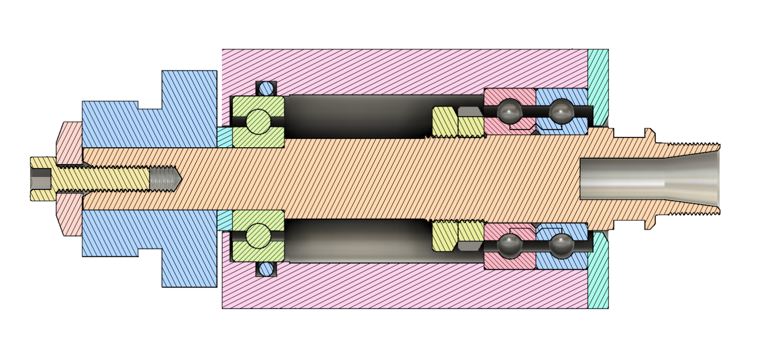
| 429 forum posts 268 photos | Critical comment time! Preliminary drawings for my spindle with a few critical dimensions. Front end first - The rear - And for wht it's worthh, the whole thing -
The colours are for clarity, they are not meant to represent materials. Steve |
| duncan webster | 22/07/2023 19:21:46 |
| 5307 forum posts 83 photos | Is that to scale? You can buy ring nuts from SKF, but not to those odd sizes. If you bore the centre section to say 14.5 diameter you can assemble the bearing to the shaft first, then slide the whole thing in from the front, this is a lot easier than trying to assemble the back bearing in situ. 7mm ring abutting a 7.2 mm step isn't a lot, you could omit the M7.9 nut and have a sleeve between the bearings |
| HOWARDT | 22/07/2023 19:41:45 |
| 1081 forum posts 39 photos | Minor diameter of M16.2x0.5 is 15.7, so that is a no, would need to be at least 16.5. Spacers between both inner and outer rings at the front, ground to suit the bearings will give some preload, otherwise nut is not locked in place. Use a snap ring below the upper bearing to give a larger thrust shoulder. Use M7x0.5 for rear thread, no point in odd size. As previous bore through for simple assembly. Make front pair bearing nut M8x0.5. It is quite normal for the bearing locknut threads to be same size as bearing bore. Machine to ensure concentricity of all bores. At 15k use light air oil lubrication, will also help o keep the swarf out. |
| Andy_G | 22/07/2023 21:48:33 |
 260 forum posts | As Howard said, the SKF literature is well worth a read. 'Design Considerations' from page 57 onwards: I went through what seems to be a similar thought process when trying to design a decent ER11 spindle for my CNC, but ended up with the arrancement below, that could be pre-assembled to the shaft before inserting into the housing: (I rejected designs based on ER11 collet extensions, as they resulted in a greater than necessary tool overhang.)
The nose bearings are a pair of matched A/C bearings from China.
I was very pleased with the outcome - about 4µm runout on the tool shank.
More words and pictures here:
|
| Steve Crow | 22/07/2023 23:17:09 |
| 429 forum posts 268 photos | Posted by HOWARDT on 22/07/2023 19:41:45:
Minor diameter of M16.2x0.5 is 15.7, so that is a no, would need to be at least 16.5. Spacers between both inner and outer rings at the front, ground to suit the bearings will give some preload, otherwise nut is not locked in place. Use a snap ring below the upper bearing to give a larger thrust shoulder. Use M7x0.5 for rear thread, no point in odd size. As previous bore through for simple assembly. Make front pair bearing nut M8x0.5. It is quite normal for the bearing locknut threads to be same size as bearing bore. Machine to ensure concentricity of all bores. At 15k use light air oil lubrication, will also help o keep the swarf out. My error the, thread should be M17 x 0.5. The odd sizes were just meant to show clearance on the thread crest. Effectively, they'll be M7 and M8. I'm only planning to buy in the bearings - I'd like to make all the other parts myself. |
| Kiwi Bloke | 22/07/2023 23:37:55 |
| 912 forum posts 3 photos | Not a criticism, but a suggestion... The design can be simplified, removing one screw-cutting operation, and making the spindle itself simpler to machine. Instead of a ring nut against the nose bearing inner track, a tubular spacer can be substituted, between the inner tracks of the inner nose bearing and the inner track of the tail-end bearing. Everything is tightened up by the tail-end nut. The tubular spacer should be a close fit to the spindle shaft, and will increase stiffness as a bonus. Probably need a simple locking arrangement for the ring nut abutting the outer track of the outer nose bearing. |
| John MC | 23/07/2023 10:38:05 |
 464 forum posts 72 photos | A rather complex solution that can be simplified as Kiwi bloke suggests. Also, remove the spacer between the two nose bearings, clamp them together. Maybe a circlip rather than the M16 threaded holding the outer races? The mounting of the third bearing is as it should be. Another thought. Why not reduce the overhang from the nose of the spindle by removing what looks like a plain diameter with spanner flats(?). Then contrive something at the other end of the spindle to hold it while tightening the collet nut. Its good to see a design that doesn't (grossly) over constrain the bearings as many do, that are published in the world of ME.,
|
| Steve Crow | 23/07/2023 11:18:08 |
| 429 forum posts 268 photos | Thanks for alll the suggestions. I'm all for simplifying things. The tubular spacer sounds a good idea, I will do another drawing. Reducing the overhang as John MC also sound good but I'll only lose 4mm that way. Still worth doing. The spacer between the nose bearings was an earlier suggeston from Kiwi Bloke though maybe I misinterpreted it. Regarding the internal circlip at the nose, I thought you would need a degree of adjustment here to clamp the outer race against the housing shoulder? As for suggestions that I bore right through 14.5mm so I can fully assemble the spindle first, I don't understand how I would secure and locate the rear bearing? Steve
Edited By Steve Crow on 23/07/2023 11:25:24 |
| Kiwi Bloke | 23/07/2023 11:48:53 |
| 912 forum posts 3 photos | The tail-end bearing's inner track is sandwiched between spacer tube and nut, so that's OK. The spindle is fully axially located at the nose end. The outer track of the tail-end bearing should be allowed to 'float' (a snug, sliding fit), to take care of possible thermal expansion. Andy_G's illustration of an O ring bearing on the outside of this track is good practice - it reduces the ability of the track to slowly walk around the bore of the housing. Agreed that you can't fully assemble the spindle before assembly into the housing, but all the important bits can be in place, except pulley and nut, of course. I'd keep the nose bearing spacer, unless you're going to buy expensive matched pair bearings. Adjustability is good... Talk to your bearing supplier about bearing seals. It's possible to get non-contact 'seals' that don't drag on the spindle. Conventional seals can add a surprising amount of drag. And oil is probably preferable to grease. (I think someone else said that, but I'm editing this now, and can't see previous posts...) Having now re-read the whole thread properly, I'm conscious that I've essentially re-stated Duncan Webster's ideas, although perhaps with different emphasis. It wasn't my intention to steal his thunder. Just two (great?) minds thinkng alike (or suggesting standard solutions...). It's heading towards being a really nifty, scalable spindle. Well worth your writing it up for MEW. It would raise the tone of the mag considerably... {Edited: it's difficult to type with fists...) Edited By Kiwi Bloke on 23/07/2023 11:55:06 |
| Kiwi Bloke | 23/07/2023 12:02:18 |
| 912 forum posts 3 photos | Apologies, it's bed-time. I shouldn't post this late - nurse will be cross. There may be some confusion about boring through the housing. There needs to be a step for the inner nose-end bearing's outer track to abut. You could have a loose, but well-fitting sleeve here, behind which is an internal circlip. The sleeve is so that the outer track abuts a reliably 'square' abutment, not a swash-plate. The tail-end bearing can have a smaller ID, so the spindle components can still be loaded from the nose end. But these complications aren't really that important. Loading the tail end bearing into the housing, with the spindle in place wouldn't be that difficult. Time for bed... |
| Steve Crow | 23/07/2023 16:39:07 |
| 429 forum posts 268 photos | I'm really appreciating all this advice and I've tried to work in the suggestions for these drawings-
The second one can be assembled first and has a beefier spacer. Things are getting simpler! All comments welcome. Steve |
| Iain Downs | 23/07/2023 17:49:51 |
| 976 forum posts 805 photos | I'm very interested in this thread as I've been in the process of building a similar type of spindle, but somewhat more naively. In my approach, I only have one bearing at each end and I'm interested in what sort of issues this is likely to cause. In one design (I'm trying several!), I have the bearings loctited in each end, a loctited washer to act as a stop at the collet end and a nut to apply preload. I'm using various chinese components, especially for the spindle proper (extension rods they call them), which I don't believe I can produce to anything like the needed accuracy. I look forward to hearing how it goes!
Iain |


Please login to post a reply.
Magazine Locator
Want the latest issue of Model Engineer or Model Engineers' Workshop? Use our magazine locator links to find your nearest stockist!
Sign up to our Newsletter
Sign up to our newsletter and get a free digital issue.
You can unsubscribe at anytime. View our privacy policy at www.mortons.co.uk/privacy
Latest Forum Posts
- *Oct 2023: FORUM MIGRATION TIMELINE*
05/10/2023 07:57:11 - Making ER11 collet chuck
05/10/2023 07:56:24 - What did you do today? 2023
05/10/2023 07:25:01 - Orrery
05/10/2023 06:00:41 - Wera hand-tools
05/10/2023 05:47:07 - New member
05/10/2023 04:40:11 - Problems with external pot on at1 vfd
05/10/2023 00:06:32 - Drain plug
04/10/2023 23:36:17 - digi phase converter for 10 machines.....
04/10/2023 23:13:48 - Winter Storage Of Locomotives
04/10/2023 21:02:11 - More Latest Posts...
- View All Topics
Support Our Partners


Shopping Partners
Subscription Offer

Latest "For Sale" Ads
- Reeves** - Rebuilt Royal Scot by Martin Evans
by John Broughton
£300.00 - BRITANNIA 5" GAUGE James Perrier
by Jon Seabright 1
£2,500.00 - Drill Grinder - for restoration
by Nigel Graham 2
£0.00 - WARCO WM18 MILLING MACHINE
by Alex Chudley
£1,200.00 - MYFORD SUPER 7 LATHE
by Alex Chudley
£2,000.00 - More "For Sale" Ads...
Latest "Wanted" Ads
- D1-3 backplate
by Michael Horley
Price Not Specified - fixed steady for a Colchester bantam mark1 800
by George Jervis
Price Not Specified - lbsc pansy
by JACK SIDEBOTHAM
Price Not Specified - Pratt Burnerd multifit chuck key.
by Tim Riome
Price Not Specified - BANDSAW BLADE WELDER
by HUGH
Price Not Specified - More "Wanted" Ads...
Get In Touch!
Do you want to contact the Model Engineer and Model Engineers' Workshop team?
You can contact us by phone, mail or email about the magazines including becoming a contributor, submitting reader's letters or making queries about articles. You can also get in touch about this website, advertising or other general issues.
Click THIS LINK for full contact details.
For subscription issues please see THIS LINK.
Digital Back Issues


Donate

 Register
 Log-in
Model Engineer Magazine
- Percival Marshall
- M.E. History
- LittleLEC
- M.E. Clock

ME Workshop
- An Adcock
- & Shipley
- Horizontal
- Mill

Subscribe Now
- Great savings
- Delivered to your door

Pre-order your copy!
- Delivered to your doorstep!
- Free UK delivery!
All Forum Topics > General Questions > Multiple Bearings in Spindle