Forum sponsored by:

3018 CNC Router/digitizer/laser cutter modifications and upgrades
| Russ B | 02/04/2023 21:20:05 |
| 635 forum posts 34 photos | I thought I'd start a separate thread specific to modifications to my SainSmart 3018 Prover V2. I welcome comments, but I wish I could reserve multiple first messages and edit them retrospectively so I can keep a post per upgrade and edit as I do it/learn from the experience to keep it all in one place. never mind!
1) A 3d touch probe so I can physically scan objects and/or engrave/laser/mill curved surfaces and zero stock/centre find etc. Using the machine as a scanner was the primary reason for buying it. 2) The X axis gantry runs on two round bars, and it flexes a lot, it might be ok for engraving and light or steady cnc routing but the rest of machine frame is really quite solid, it can be significantly improved with a minor tweak and about £60. This invloves fitting a pair of MGN type rails directly to the existing 2020 vee channel seen behind the existing round bars - the round bars and bearings go in the parts bin. A new saddle will be designed and 3D printed, and if/when more serious work takes place, something more metallic might emerge from scraps. 3) Stock motor details are few and far between but I think its rated about about 10k, 1.5A 12v.... I'm not sure how these numbers add up but it runs at 24v 10krpm apparently, independent tests online confirm it hits about 9krmp @ 1.6A 24v no load. There are multiple "upgrades" on the manufacturers website and I happen to have a European made 20k motor that exactly matches the specification of the Chinese 20k spindle upgrade they advertise but mine has a far superior brush assembly, shorter body but higher weight, its a direct fitment. I've tested it already and it's got significantly more welly at the same output but appears to be turning at roughly the same speed, someone has borrowed my RPM meter and I'm not sure how these PWM speed controllers really work, so its up in the air a bit. The spindle was set to the same rpm and I just assumed fitting a motor with twice the rpm would result in, double the RPM.... as I said, I'm not sure if that's how DC PWM speed control works. 4) The Z axis ....is plastic but seems solid enough, however it only has very limited travel and I can see that being more of an inconvenience than anything, the first thing I wanted to test engrave (a piece of 11mm board) couldn't be reached, I had to stack a couple and redo the clamps. The saddle that carries the Z assembly and rides on the X rails, will be no use when I change the X bearings and their layout. I will 3D print a new one and mount the spindle as close to the new X rails as physically possible, I noticed quite a distance between spindle centre and X axis centre which increases leverage and promotes twisting in the X bearings, any reduction here will further improve rigidity. I will also widen the bearing spacing, reducing my X travel, but increasing rigidity especially if/when milling!. 5)Laser.... I've always wanted one...... the PCB has 2 headers for a laser and air assist and the manufacturer does their own 5.5w concentrated spot laser with a fixed focal length (I guess that's 5.5w input power not output but I don't know, the header supports upto 2 amp) 6) Possibly moving the Y bearings and maybe even rails back to the positioning on previous version of this machine, it has less travel, but should be more stable for light milling work, I was unhappy with the saddle as it was narrower, and then I noticed the bearings and rails under the bed were quite narrow too, and then I spotted the specification change, increasing travel on all axes, I double checked a few frame dimensions and it's the same, so they must've narrowed the bearings. The controller on the V2 is a significant upgrade, featuring headers for the lasers, better drivers IIRC, a better 32bit arm GRBL controller vs the previous (presumably arduino) 8bit GRBL controller and limit switches preinstalled on all axes + 2 spare..... now 1 spare.... whoops, I don't know my own strength... No time scale for the above. I bought the machine purely to digitise some parts that are practically impossible to measure and/or have bizare contours and stuff, I need accurate 3D models to realise another dream, to run CFD on heat transfer and fluid flow though various parts. I will probably use the machine to make balsa dummies for test fitting, if it can one day actually machine soft aluminium, I will give it a shot but I suspect I'll be paying someone else to machine the finished parts properly, as the softness of the alloy makes it quite tricky to machine without damaging. Edited By Russ B on 02/04/2023 21:28:51 Edited By Russ B on 02/04/2023 21:35:31 |
| IanT | 03/04/2023 12:23:39 |
| 2147 forum posts 222 photos | I've managed to resist buying one of these cheap 'engravers' Russ as I'm not sure of it's practical value if you are already set up with manual machines (at least for most of what I do). But then I didn't originally think I really needed a 3D Printer and I've found a lot of uses for that. Learning 3D CAD made a big difference in my case. It wouldn't be nearly as useful if I was just printing Thingiverse designs.... So I'll be interested in hearing how you progress. Regards,
IanT |
| John Haine | 03/04/2023 12:57:43 |
| 5563 forum posts 322 photos | Ballscrews might be a good upgrade if not already fitted. For the X (I assume you mean left-right) axis, it looks like the electronics are bolted to the back of the rear rails. Removing that and fitting a piece of 6mm plate right across, bolted into the edges of the side "cheeks" would be a lot more rigid. A Z axis assembly fabricated from alloy plate would be more rigid than plastic if you want to do routing. Even on a proper mill pure soft aluminium is horrid to machine, much better to use a machinable alloy (6082?). A material which is a delight to machine is Corian, get offcuts from an up-market kitchen fitter. Good for making precise parts that don't need to be very hard or strong. There is a material not unlike MDF called Valchromat which uses a melamine resin rather than urea formaldehyde. It routes very well, doesn't blunt cutters like MDF, is through-coloured, and not nearly so unfriendly to breath the dust. Great for things like spoil boards, small sacrificial mounting plates etc. Expensive to buy an 8x4 sheet so try to get offcuts. I actually got a sun-bleached sheet almost free that had been in a showroom, I also made a clock case from new stuff (blue), I had the components CNC routed and took away all the offcuts too, I seem to have a lifetime supply at least for small projects. Basically the rpm of a typical DC motor depends on the number of turns, the magnetic circuit design, and the applied voltage. So a motor that runs at 10,000rpm on a 24v supply will very nearly be generating 24v back emf with no load. At 12v the same motor would run at 5,000rpm. Controlling by PWM, you take the "duty cycle" which is the ratio of on time to on+off time and multiply the supply voltage by that fraction to find the effective voltage. So a 24v 10,000rpm motor supplied at 24v with 50% duty cycle will run at 5000rpm. |
| Dick H | 03/04/2023 14:01:13 |
| 141 forum posts 1 photos | I got one of these in kit form a few years ago just to play with (ie. not the slick SainSmart machine.). The original electronics was very probably arduino based and had the name "Woodpecker" inscribed on the PCB. The electronics were very prone to electrical interference, crashing at odd moments. In the original SainSmart lit. they add capacitors to the motor stop this, I tried this with my primitive setup and it smoked the capacitors so I moved on to attachable ferrite rings and a big diode the "wrong" way round to trap the back emf of the motor. The SainSmart box of electronics seems more stable although I did manage to wreck a MosFet controlling the motor on one. Adding MGN type rails in addition to the rods on the x-axis makes a lot of difference to the rigidity (somewhere out there an Australian user describes his mods). The z-axis is made from 3D printed parts but seems relatively OK. Thingiverse has recipes for improved and larger capacity mounts but a bigger spindle would bring larger loadings and strains. Where do you you stop? I tinkered with the anti-backlash nuts on the x-axis drive in that I added screws to push off the brass to positively take up the slack rather than rely on the spring between the two brass fittings on the drive screw.. At the end of the day the 3018 is a learning tool, an engraver. What I need is a source of easy material to machine to play with and not be too upset when it lands in the bin. |
| An Other | 03/04/2023 20:45:48 |
| 327 forum posts 1 photos | Link - May be of interest.
|
| Andy_G | 06/04/2023 14:46:26 |
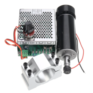
 260 forum posts | Posted by Russ B on 02/04/2023 21:20:05:
3.The spindle motor I can recommend steering clear of this style of spindle motor (ubiquitous on Amazon, Aliexpress, etc.) on grounds of both electrical safety and mechanical shortcomings.
My ultimately unsuccessful attempt to make a silk purse out of a sow's ear:
|
| Michael Gilligan | 06/04/2023 17:27:32 |
 23121 forum posts 1360 photos | Nicely presented, Andy MichaelG. |
| Andy_G | 06/04/2023 21:55:06 |
260 forum posts | Thank you! |

Please login to post a reply.
Magazine Locator
Want the latest issue of Model Engineer or Model Engineers' Workshop? Use our magazine locator links to find your nearest stockist!
Sign up to our Newsletter
Sign up to our newsletter and get a free digital issue.
You can unsubscribe at anytime. View our privacy policy at www.mortons.co.uk/privacy
Latest Forum Posts
- *Oct 2023: FORUM MIGRATION TIMELINE*
05/10/2023 07:57:11 - Making ER11 collet chuck
05/10/2023 07:56:24 - What did you do today? 2023
05/10/2023 07:25:01 - Orrery
05/10/2023 06:00:41 - Wera hand-tools
05/10/2023 05:47:07 - New member
05/10/2023 04:40:11 - Problems with external pot on at1 vfd
05/10/2023 00:06:32 - Drain plug
04/10/2023 23:36:17 - digi phase converter for 10 machines.....
04/10/2023 23:13:48 - Winter Storage Of Locomotives
04/10/2023 21:02:11 - More Latest Posts...
- View All Topics
Support Our Partners


Shopping Partners
Subscription Offer

Latest "For Sale" Ads
- Reeves** - Rebuilt Royal Scot by Martin Evans
by John Broughton
£300.00 - BRITANNIA 5" GAUGE James Perrier
by Jon Seabright 1
£2,500.00 - Drill Grinder - for restoration
by Nigel Graham 2
£0.00 - WARCO WM18 MILLING MACHINE
by Alex Chudley
£1,200.00 - MYFORD SUPER 7 LATHE
by Alex Chudley
£2,000.00 - More "For Sale" Ads...
Latest "Wanted" Ads
- D1-3 backplate
by Michael Horley
Price Not Specified - fixed steady for a Colchester bantam mark1 800
by George Jervis
Price Not Specified - lbsc pansy
by JACK SIDEBOTHAM
Price Not Specified - Pratt Burnerd multifit chuck key.
by Tim Riome
Price Not Specified - BANDSAW BLADE WELDER
by HUGH
Price Not Specified - More "Wanted" Ads...
Get In Touch!
Do you want to contact the Model Engineer and Model Engineers' Workshop team?
You can contact us by phone, mail or email about the magazines including becoming a contributor, submitting reader's letters or making queries about articles. You can also get in touch about this website, advertising or other general issues.
Click THIS LINK for full contact details.
For subscription issues please see THIS LINK.
Digital Back Issues


Donate

 Register
 Log-in
Model Engineer Magazine
- Percival Marshall
- M.E. History
- LittleLEC
- M.E. Clock

ME Workshop
- An Adcock
- & Shipley
- Horizontal
- Mill

Subscribe Now
- Great savings
- Delivered to your door

Pre-order your copy!
- Delivered to your doorstep!
- Free UK delivery!
All Forum Topics > CNC machines, Home builds, Conversions, ELS, automation, software, etc tools > 3018 CNC Router/digitizer/laser cutter modifications and upgrades