Forum sponsored by:

Warco Major mill wiring
| Stuart Barker 1 | 01/07/2014 15:57:06 |
| 7 forum posts | Hello, I am hoping someone can help me please. I have a Warco Major mill/drill MD30B and while trying to fault find too the switch wiring apart without taking a photo
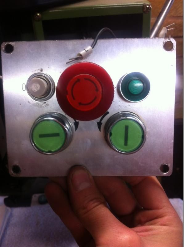
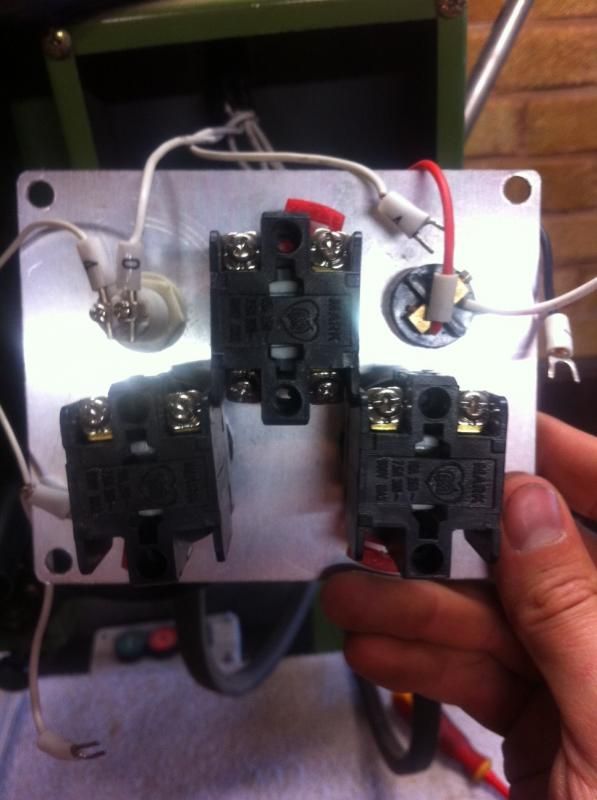
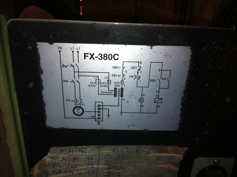
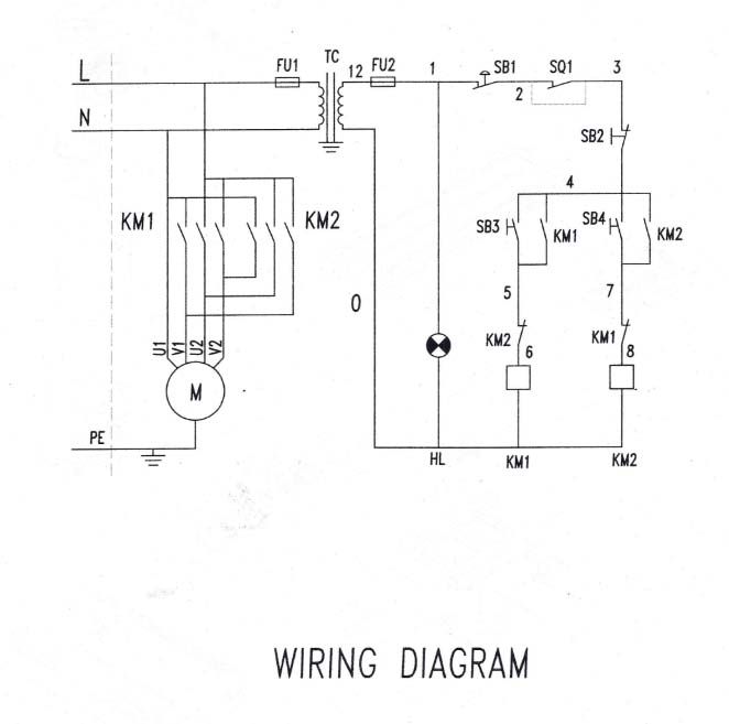
The pictures show the wiring diagram in the back of the mill and my switch panel. the wires are as follows. Red:7 Balck:8 White: 0,2,3, Two 4’s one has three connections, 5,6 and another 8. if someone has a Warco Major Mill/Drill and would mind taking a picture of there switch wiring that would be amazing. or could explain the sequence. Any help would be greatly appreciated as at the moment i can't use it at all... Edited By Stuart Barker 1 on 01/07/2014 16:02:13 |
| martin perman | 01/07/2014 16:27:06 |
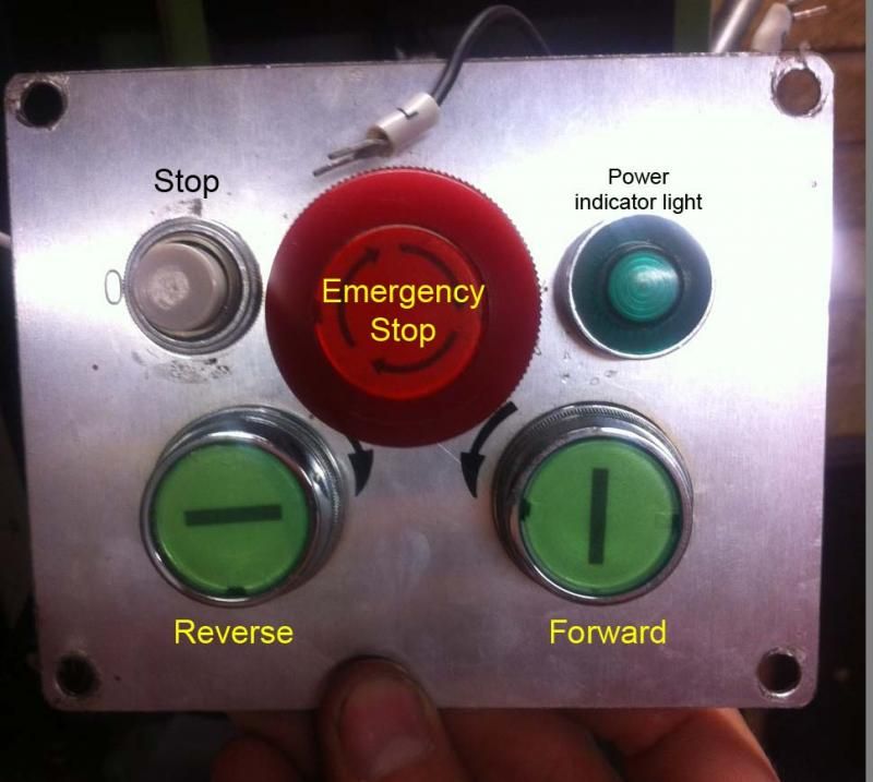
 2095 forum posts 75 photos | Can you describe the button panel, EM stop with light to right and power on to left, you dont have reverse on the motor so what do the green buttons do. Martin P
|
| Stuart Barker 1 | 01/07/2014 17:07:17 |
| 7 forum posts | Twist emergency stop to release and engage power so the light is on, the lower green buttons are forward and reverse, the white button top left is normal stop.
|
| martin perman | 01/07/2014 17:10:35 |
2095 forum posts 75 photos | then the diagram you are showing doesnt show FWD or Reverse
Martin P |
| Stuart Barker 1 | 01/07/2014 17:27:39 |
| 7 forum posts | that diagram in in the back of the mill, |
| martin perman | 01/07/2014 17:57:07 |
2095 forum posts 75 photos | The drawing is self explanatory, based on what you have shown so far SQ1 is an option, I think, as you only have shown four buttons, KM1 and KM2 are the coils for the motor contacts, SB3/SB4 are the FWD/REV buttons, SB1 is the EM stop and SB2 is the stop button,FU1 and FU2 are fuses and the quartered circle is the lamp, connect your numbered wires upto the various listed parts. Martin P
|
| Stuart Barker 1 | 01/07/2014 18:45:58 |
| 7 forum posts | Ok, but i dont have a wire labeled 1 to go to my EM stop button. I have a 4 wire with three terminals starting at the light and then another singe 4 wire. Sorry to be so thick! i just cant get my head around it. |
| martin perman | 01/07/2014 18:53:21 |
2095 forum posts 75 photos | do you have a wire from the light and a wire from the fuse, if yes put these into one side of the EM stop or seek an electrician that can do it for you.
Martin P |
| Les Jones 1 | 02/07/2014 08:07:58 |
| 2292 forum posts 159 photos | Hi Stuart, Les. Edited By Les Jones 1 on 02/07/2014 08:08:38 |
| Les Jones 1 | 02/07/2014 20:45:41 |
| 2292 forum posts 159 photos | I have just read through the thread again and the statement "Twist emergency stop to release and engage power so the light is on" would suggest that the mill is not wired in quite the same way as the second diagram suggests. It suggests that the top wire from the indicator lamp connects after the emergency stop button. This means that it may be connected to point 2, 3, or 4 rather than point 1 as shown in the diagram. If connected as the diagram it would remain on even when the emergency stop button was pressed in. Les. |
| paul mcquaid | 26/03/2023 18:41:27 |
| 34 forum posts 12 photos | Hello Stuart, I know this is a long shot,But I noticed you have a Warco Major MD30B, Which is the same model I have and was just wondering if you could tell me how to tram the head? The only manual I could find was for a different model of Major which has two bolts to undo, Mine as far as I can see only has one large nut with a large chrome handle that you can undo to pivot the head or crank the handle to raise and lower on the rack and pinion. How does anyone know how these mills work? As I can't find any thing on you tube that specifically says what each handle, Bolt , etc does and the manuals are next to useless. Perhaps you could tell me a book that covers the use of this type of Round Column Mill. |
| Oldiron | 26/03/2023 22:24:38 |
| 1193 forum posts 59 photos | Posted by paul mcquaid on 26/03/2023 18:41:27:
Hello Stuart, I know this is a long shot,But I noticed you have a Warco Major MD30B, Which is the same model I have and was just wondering if you could tell me how to tram the head? The only manual I could find was for a different model of Major which has two bolts to undo, Mine as far as I can see only has one large nut with a large chrome handle that you can undo to pivot the head or crank the handle to raise and lower on the rack and pinion. How does anyone know how these mills work? As I can't find any thing on you tube that specifically says what each handle, Bolt , etc does and the manuals are next to useless. Perhaps you could tell me a book that covers the use of this type of Round Column Mill. I think tramming is only possible using shims under the column base plate. regards |
| paul mcquaid | 26/03/2023 23:04:32 |
| 34 forum posts 12 photos | Thank you. This is what I thought until a you tube video by multiple people kept saying just undo a couple of bolts and tap lightly with mallet. to set it up and then found when Warco sent a PDF of thier current major it was different too. But at the end of the day tramming for this model is basically stuffing a packing piece to which ever side levels the head measurement on a DTI. Is there a way to measure for being dead centre of the table I.E so it doesn't cut an uneven depth as well as the height? |
| Dave Halford | 27/03/2023 09:56:40 |
| 2536 forum posts 24 photos | Posted by paul mcquaid on 26/03/2023 23:04:32:
Thank you. This is what I thought until a you tube video by multiple people kept saying just undo a couple of bolts and tap lightly with mallet. to set it up and then found when Warco sent a PDF of thier current major it was different too. But at the end of the day tramming for this model is basically stuffing a packing piece to which ever side levels the head measurement on a DTI. Is there a way to measure for being dead centre of the table I.E so it doesn't cut an uneven depth as well as the height? Thats shown in the Utube link i put in your first thread. |
 i have another which is this.
Please login to post a reply.
Magazine Locator
Want the latest issue of Model Engineer or Model Engineers' Workshop? Use our magazine locator links to find your nearest stockist!
Sign up to our Newsletter
Sign up to our newsletter and get a free digital issue.
You can unsubscribe at anytime. View our privacy policy at www.mortons.co.uk/privacy
Latest Forum Posts
- *Oct 2023: FORUM MIGRATION TIMELINE*
05/10/2023 07:57:11 - Making ER11 collet chuck
05/10/2023 07:56:24 - What did you do today? 2023
05/10/2023 07:25:01 - Orrery
05/10/2023 06:00:41 - Wera hand-tools
05/10/2023 05:47:07 - New member
05/10/2023 04:40:11 - Problems with external pot on at1 vfd
05/10/2023 00:06:32 - Drain plug
04/10/2023 23:36:17 - digi phase converter for 10 machines.....
04/10/2023 23:13:48 - Winter Storage Of Locomotives
04/10/2023 21:02:11 - More Latest Posts...
- View All Topics
Support Our Partners


Shopping Partners
Subscription Offer

Latest "For Sale" Ads
- Reeves** - Rebuilt Royal Scot by Martin Evans
by John Broughton
£300.00 - BRITANNIA 5" GAUGE James Perrier
by Jon Seabright 1
£2,500.00 - Drill Grinder - for restoration
by Nigel Graham 2
£0.00 - WARCO WM18 MILLING MACHINE
by Alex Chudley
£1,200.00 - MYFORD SUPER 7 LATHE
by Alex Chudley
£2,000.00 - More "For Sale" Ads...
Latest "Wanted" Ads
- D1-3 backplate
by Michael Horley
Price Not Specified - fixed steady for a Colchester bantam mark1 800
by George Jervis
Price Not Specified - lbsc pansy
by JACK SIDEBOTHAM
Price Not Specified - Pratt Burnerd multifit chuck key.
by Tim Riome
Price Not Specified - BANDSAW BLADE WELDER
by HUGH
Price Not Specified - More "Wanted" Ads...
Get In Touch!
Do you want to contact the Model Engineer and Model Engineers' Workshop team?
You can contact us by phone, mail or email about the magazines including becoming a contributor, submitting reader's letters or making queries about articles. You can also get in touch about this website, advertising or other general issues.
Click THIS LINK for full contact details.
For subscription issues please see THIS LINK.
Digital Back Issues


Donate

 Register
 Log-in
Model Engineer Magazine
- Percival Marshall
- M.E. History
- LittleLEC
- M.E. Clock

ME Workshop
- An Adcock
- & Shipley
- Horizontal
- Mill

Subscribe Now
- Great savings
- Delivered to your door

Pre-order your copy!
- Delivered to your doorstep!
- Free UK delivery!
All Forum Topics > Manual machine tools > Warco Major mill wiring