Forum sponsored by:

cutting internal gear rings
| rebekah anderson | 14/05/2013 15:47:44 |
| 135 forum posts | hiya every one. I was wondering if any one knew how to make a cutting tool in order to cut teeth in an internal gear ring. the sort of sizes I'd am looking at is as small as 25mm internal diameter of the ring. the cutter would need to be accompanied with a normal gear cutter to marry up with the internal gear ring. I have seen the keyway cutter divice that mounts on the myford and the like. which is something I'll have to make, unless there is one out there for sale. any help would be greatfully recieved. in the mean time, what is the opinion of the Myford ML2 for small hobby work. regards Becky |
| magpie | 14/05/2013 17:00:40 |
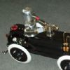 508 forum posts 98 photos | Hi Becky, Do you realy need to make the ring gear and pinion yourself ? I have some small ex WD motors that have a planetry gearbox on the end. The inside of the ring gear is about 23mm. one of these motors with gearbox could be yours for £5.00 plus postage. they are a really nice bit of tackle, so i will put a photo in my album. The ring gear is the one in the middle of the pic an has six mounting holes around the edge,and the planet gears (3 of them) are shown on a carrier. If they will do the job send me a PM. Cheers Derek. P.S. sorry the photo is a bit hazy. |
| rebekah anderson | 14/05/2013 17:08:56 |
| 135 forum posts | Looks pretty good but i need to make my own. As there are a variety that i need to make. Applications are the slew gear for a hiab crane, drive gear for the sprockets on a digger. So really would like the tools to make them. |
| Brian Wood | 14/05/2013 17:23:49 |
| 2742 forum posts 39 photos | Hello Becky, I inherited my father's ML4 which superceded the ML2 and did a lot of work with it. If you can find a nice one at a reasonable price and complete, there is no reason why you shouldn't be completely happy with it. One modification I would recommend would be to make and loctite on a close fitting collar for a chuck register of ML7 Myford size [ie 1.250 inch diameter] Complete the turning with it installed to keep things absolutely true and concentric. You may have to use a little ingenuity to get turning tools to reach that close to the headstock. You will then be able to fit readily available Myford fitting chucks and faceplates without searching for the smaller and scarcer 1.125 inch versions that the spindle was made for I found that very worthwhile on Dad's lathe and altered the chucks that came with it to fit the new size Happy turning Brian |
| rebekah anderson | 14/05/2013 17:32:03 |
| 135 forum posts | Thank you for the tip. I'll look into applying the mod. I've got a sieg C3 at the mo but just wanted something more for my work. This is what i bought. http://s526.photobucket.com/albums/cc346/rebekah3505/?action=view¤t=8bf5b9dccff8cd5b0ff17274a0ce650e_zps29ae724d.jpg Edited By rebekah anderson on 14/05/2013 17:33:10 |
| JasonB | 14/05/2013 17:45:35 |
 25215 forum posts 3105 photos 1 articles | If you can draw out the gear profile then grind a tool to that shape and use the planing method in the lathe, you don't need the straking tool it can be done by using the carrage handwheel, the setup would be similar to this The other way is to make a broach similar to a spline broach which is pushed through a ring cutting the teeth as it goes Edited By JasonB on 14/05/2013 17:46:24 |
| rebekah anderson | 14/05/2013 17:53:30 |
| 135 forum posts | That's the sort of tool i'm looking for. Not sure how to make it though. the broach is out of my league lol |
| Michael Cox 1 | 14/05/2013 18:35:22 |
| 555 forum posts 27 photos | Hi Becky, I do not know what material is necessary for your part but if plastic were acceptable then have a look at madmodder.net and search for "forming plastic gears. The method, as shown is used to form external gears but I cannot see why it would not work to form internal gears. Mike
Edited By Michael Cox 1 on 14/05/2013 18:37:17 |
| Brian Wood | 14/05/2013 18:36:16 |
| 2742 forum posts 39 photos | Hello Becky, That is a nice looking lathe, did it look that that when you bought it? Was backgear an ML4 addition? Brian |
| JasonB | 14/05/2013 18:40:42 |
25215 forum posts 3105 photos 1 articles | Becky, the tooling is quite easy to make. You just need a short length of bar say 1/2" dia, cross drill the end say 1/8" to take a HSS tool bit or even a broken centre drill and at right angles to that hole drill and tap for a grub screw.
The screw can alternatively come in from the end
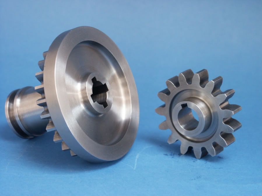
You then just need to have a way to index the work for the number of teeth you require, move the carrage back and forth feeding in say 0.005" at a time until the tooth gap is formed, rotate round to the next one and repeat. These three took me about 60secs.
I notice from your album you do a lot of work in Aluminium, I would suggest brass for the gear as its easy to work, those ones needed hardly any effort to cut. You just need to grind the end of the cutting tool to match a printed out profile of your gears. You can also use the same method to cut keyways if you do't have a suitable broach, just grind up a square ended tool
J Edited By JasonB on 14/05/2013 18:45:43 |
| Michael Gilligan | 14/05/2013 18:43:47 |
 23121 forum posts 1360 photos | Becky, For an alternative approach; have a look at the HCF and UCF on this page. If you are using Brass, Aluminium, or Plastics for the Gears then ... Set up with a suitable cutter, these have the potential to do what you need. MichaelG.
|
| Bazyle | 14/05/2013 18:45:12 |
 6956 forum posts 229 photos | The way to do it is to first think how you would make a normal gear of that size that would fit inside your internal gear with the same number of teeth ie filling it entirely like a splined shaft.
Then if you were to make that gear with just one tooth (and most of it's body not there) then that tooth is the cutter you want. If you photograph your stages it would make a nice little article. |
| rebekah anderson | 14/05/2013 19:00:43 |
| 135 forum posts | Wow guys,
i was trying to thank every one induvidually but the influx of info was overwhelming. Material of aluminium or brass. So i will give the brass a go first. Great info for making the tool. I think i will combine the two main methods on here. As for the lathe, got to be joking, bought it like that. I am decent machinist but that's way beyond me lol. I think i got an absolute bargain (well i hope) i just needed a more capable machine as the detail I am moving is getting more important. Add to this i got to learn how to get decent internal thread done too. This is for 6mm hydraulic cylinders. Thank you every one. You have inspired me for the tool and will be getting on to it in the next couple of weeks. |
| Andrew Johnston | 14/05/2013 19:38:40 |
 7061 forum posts 719 photos | I'm afraid that the method suggested by Bazyle will not give you the correct form for an internal gear tooth. The tooth spaces of an internal gear are not the same as the tooth spaces of an external gear. The design of tooth spaces for internal gears is significantly more complicated than the simple rules for external involute gears. The practical complexity depends upon the DP and number of teeth on the internal gear. One general rule is that for gears of 4DP and finer, and more than 60 teeth, a number 1 cutter can be used, ie, one intended for external gears of 135 teeth to a rack. I suspect that this might cover the slewing gear, and you could probably get away with a cutter tapered at the pressure angle of the gear, with no curves. However, as the number of internal teeth get smaller, and the external pinion gets bigger as a proportion of the internal gear, then all sorts of 'fiddle' factors are involved to allow for interferences between the teeth. For the smaller internal gears there is probably not much point in calculating the exact internal tooth forms, as I assume it would be difficult to make a small tool of the correct shape in the home workshop. A pragmatic approach would be to draw a few teeth at a large scale on graph paper and play with a few simple tooth shapes that avoid interferences while allowing a tool to be simply made. Or buy a copy of Gearotic! Regards, Andrew |


Please login to post a reply.
Magazine Locator
Want the latest issue of Model Engineer or Model Engineers' Workshop? Use our magazine locator links to find your nearest stockist!
Sign up to our Newsletter
Sign up to our newsletter and get a free digital issue.
You can unsubscribe at anytime. View our privacy policy at www.mortons.co.uk/privacy
Latest Forum Posts
- *Oct 2023: FORUM MIGRATION TIMELINE*
05/10/2023 07:57:11 - Making ER11 collet chuck
05/10/2023 07:56:24 - What did you do today? 2023
05/10/2023 07:25:01 - Orrery
05/10/2023 06:00:41 - Wera hand-tools
05/10/2023 05:47:07 - New member
05/10/2023 04:40:11 - Problems with external pot on at1 vfd
05/10/2023 00:06:32 - Drain plug
04/10/2023 23:36:17 - digi phase converter for 10 machines.....
04/10/2023 23:13:48 - Winter Storage Of Locomotives
04/10/2023 21:02:11 - More Latest Posts...
- View All Topics
Support Our Partners


Shopping Partners
Subscription Offer

Latest "For Sale" Ads
- Reeves** - Rebuilt Royal Scot by Martin Evans
by John Broughton
£300.00 - BRITANNIA 5" GAUGE James Perrier
by Jon Seabright 1
£2,500.00 - Drill Grinder - for restoration
by Nigel Graham 2
£0.00 - WARCO WM18 MILLING MACHINE
by Alex Chudley
£1,200.00 - MYFORD SUPER 7 LATHE
by Alex Chudley
£2,000.00 - More "For Sale" Ads...
Latest "Wanted" Ads
- D1-3 backplate
by Michael Horley
Price Not Specified - fixed steady for a Colchester bantam mark1 800
by George Jervis
Price Not Specified - lbsc pansy
by JACK SIDEBOTHAM
Price Not Specified - Pratt Burnerd multifit chuck key.
by Tim Riome
Price Not Specified - BANDSAW BLADE WELDER
by HUGH
Price Not Specified - More "Wanted" Ads...
Get In Touch!
Do you want to contact the Model Engineer and Model Engineers' Workshop team?
You can contact us by phone, mail or email about the magazines including becoming a contributor, submitting reader's letters or making queries about articles. You can also get in touch about this website, advertising or other general issues.
Click THIS LINK for full contact details.
For subscription issues please see THIS LINK.
Digital Back Issues


Donate

 Register
 Log-in
Model Engineer Magazine
- Percival Marshall
- M.E. History
- LittleLEC
- M.E. Clock

ME Workshop
- An Adcock
- & Shipley
- Horizontal
- Mill

Subscribe Now
- Great savings
- Delivered to your door

Pre-order your copy!
- Delivered to your doorstep!
- Free UK delivery!
All Forum Topics > Beginners questions > cutting internal gear rings