Forum sponsored by:

Lister Drawings
| HobbyNut | 19/03/2013 20:32:24 |
 113 forum posts 93 photos | I cannot seem to locate a drawing in the series so far, that tells me a few critical dimemensions of the crankcase. The height of the crankshaft from the base for instance. I remember pulling quite a few of these engines apart back in the 50's, at my fathers Engine Reconditioning shop in Australia. I thought it would be a great next project, after I finish my present 2 or 3!! and as long as health permits.
Edited By HobbyNut on 19/03/2013 20:44:55 |
| JasonB | 19/03/2013 21:08:53 |
 25215 forum posts 3105 photos 1 articles | There are a few other missing dimensions such as overal height and length and I also queried the cam dia as its a slack fit in the gear and bearings. George is a member of the forum, if he does not reply to this thread in a day or two I will PM him or maybe Ennech can shed some light as he has drawn it out in cad. Ennech also intends to supply castings if you don't want to make your own patterns and get castings done. Edited By JasonB on 19/03/2013 21:19:09 |
| Jeff Dayman | 19/03/2013 21:12:39 |
| 2356 forum posts 47 photos | The drawings are not clear to me either. Lots of dims a machinist does not need and some missing that they do need. The non-draughtsman non-machinist non-model engineer illustrator in Greece strikes again I think. When all drawings are published I will have a go at simplifying and correcting them for my own use and for anyone interested (but not in the open forum). JD |
| craig fowler | 20/03/2013 16:27:41 |
| 16 forum posts | If the drawings are accurate enough you could simply scale off of that.... Although that isnt a very acurate way i know! |
| Jeff Dayman | 20/03/2013 17:50:29 |
| 2356 forum posts 47 photos | Craig, I do all my layouts in 3D CAD (use it professionally) so I remove all doubt about fits and sizes before cutting metal. I can't debate the accuracy of what features and sizes are shown on the published "drawings" because I don't have a full size Lister engine in front of me, but if I do lay it out myself on CAD using the ME "drawings" as a general guide to major dimensions I know nothing will interfere and I will be able to machine it to my drawings. JD |
| Diane Carney | 20/03/2013 19:51:35 |
| 419 forum posts 11 photos |
Posted by Jeff Dayman on 19/03/2013 21:12:39:
The non-draughtsman non-machinist non-model engineer illustrator in Greece strikes again I think. JD - the illustrator simply redraws the drawings to make them suitable for publication. They are then meticulously checked against the author's original before being passed for print. He is not required to have any technical input whatsoever. He is skilled at what he does and very rarely makes an error. It is not on to blame him for anything missing on a drawing. As has been mentioned, George Punter does indeed contribute to the forum occasionally but an answer may not appear immediately. I will ask him to take a look at this thread. Diane |
| JasonB | 20/03/2013 20:17:09 |
25215 forum posts 3105 photos 1 articles | Diane, I have already started to make a list of items that I would like George to take a look at so if you want to leave it to me I will PM him tomorrow. I have already exchanged a few PMs with him. Regarding what you said above, this does highlight one of the problems, a non technical illustrator faithfully reproduced what a contributor sends in. This reproiduction is then checked against the original drawing like for like but nobody with a technical understanding looks at the drawing so errors in the original will just be passed on to the published drawing. This may be why we have 6.0mm shafts mating with 6.4mm holes, Items in one view dimensioned 7.0mm and 7.09mm in another, a 3mm hole also dimensioned 3.4mm, etc. I'm not knocking Georges work but these sort of things would could be picked up by someone with an enquiing technical mind before they ever go to print. J |
| Diane Carney | 21/03/2013 09:25:29 |
| 419 forum posts 11 photos | No problem Jason. I am happy to leave the co-ordination to you.
In recent issues, Stewart has been pretty sharp at pointing out exactly those kinds of errors and has corected a few. Even I spotted one!!! I can't vouch for what has gone before, of course. And, to be fair to the illustrator, he does pick up on obvious errors on occasions. That said, we can not be expected to pick up on missing dimensions etc. as we are not constructing the part/model. Also part A might be mating with part B which may be several issues down the line. There is therefore no way of avoiding some errors getting through onto the page. Hence the section of this forum dedicated to correcting drawing errors. Diane
|
| Jeff Dayman | 21/03/2013 12:33:47 |
| 2356 forum posts 47 photos | "He is skilled at what he does and very rarely makes an error." With respect Diane, I don't agree. In the last few years errors and poor draughting practices from the illustrator have been discussed several times in this forum. At the very least, I suggest some reading on basic engineering drawing practice before preparing drawings for a technical magazine like ME. A good place to start would be "a manual of engineering drawing practice" by Simmons and Maguire, isbn 0 340 17996 1. (or its' modern equivalent.) It is a mistake in my opinion to accept mediocrity in any engineering drawing especially when training and literature on the basic techniques is freely available. If you compare the illustrator's work to excellent drawings by others like Alan Jackson (recent stepperhead lathe) Neville Evans (various locomotives) or Anthony Mount (stationary engines) there is a world of difference. Best regards JD |
| David Clark 1 | 21/03/2013 12:47:58 |
 3357 forum posts 112 photos 10 articles | Hi There I believe I arranged for a copy of the relevant BS manual to be sent to the illustrator a couple of years ago. I doubt Diane has a copy though. I can't remember what it is called, I will dig my copy out over the weekend if I have time. regards david |
| Stub Mandrel | 22/03/2013 11:44:42 |
 4318 forum posts 291 photos 1 articles | The Tubal Cain book in the WPS series might be easier for a non-engineer to digest. Neil |
| JasonB | 23/03/2013 08:05:46 |
25215 forum posts 3105 photos 1 articles | Just an update, I have heard back from George, just one query to confirm and then I will post the list of missing details. J |
| Diane Carney | 23/03/2013 09:34:30 |
| 419 forum posts 11 photos | Posted by David Clark 1 on 21/03/2013 12:47:58:
the relevant BS manual .... I doubt Diane has a copy though. That's the question... which 'Standard' are we working to? I will get the right one out.
|
| JasonB | 23/03/2013 09:47:44 |
25215 forum posts 3105 photos 1 articles |
BS 8888 or the older BS 308 but as Neil says Tubal Cain's book No 13 in the WS series would make easier reading MHS may even give you a discount Myself I would just be happy to have all the info to make the part and no errors, can be laid out as the contributor wishes. J Edited By JasonB on 23/03/2013 10:00:59 |
| JasonB | 26/03/2013 10:53:10 |
25215 forum posts 3105 photos 1 articles | Some revisions here, crankshaft ctr height to follow |
| HobbyNut | 02/04/2013 15:46:57 |
113 forum posts 93 photos |
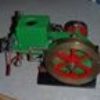
George has been gracious enough to send me any info I want. I cut and welded this yesterday, to see what a fabricated crankcase would be like. The ribs between the RH bosses are for fabricating and cutting ease. All holes are undersize. I will cut the base, top and ends today. maybe get it assembled tonight. |
| JasonB | 02/04/2013 16:12:09 |
25215 forum posts 3105 photos 1 articles | That looks good, I've fabricated parts in a similar way but my welding is not as good as yours. J |
| HobbyNut | 02/04/2013 18:27:37 |
113 forum posts 93 photos | Thanks Jason, my welding aint as good as it used to be, mainly because ,my sight aint either! I just finished cutting the base, the cylinder mounting plate(top), the RH end, flange and cover. I intend to cut the LH end from 2" MS plate, it takes 40 mins on the waterjet. |
| JasonB | 02/04/2013 18:31:49 |
25215 forum posts 3105 photos 1 articles | Oh thats a thick bit, I would have used a flat plate at the bottom and a suitable section of tube but I suppose if you can get the WJ for free then why not. How much taper is the waterjet likely to leave over the 2" thickness? I've only had stuff upto 10mm cut and its noticable on that. |
| Stub Mandrel | 02/04/2013 18:50:15 |
4318 forum posts 291 photos 1 articles | I wish that I could weld like that. My welds look like the death throes of a convoy of poisoned slugs. Neil Edited By Stub Mandrel on 02/04/2013 18:51:06 |


Please login to post a reply.
Magazine Locator
Want the latest issue of Model Engineer or Model Engineers' Workshop? Use our magazine locator links to find your nearest stockist!
Sign up to our Newsletter
Sign up to our newsletter and get a free digital issue.
You can unsubscribe at anytime. View our privacy policy at www.mortons.co.uk/privacy
Latest Forum Posts
- hemingway ball turner
04/07/2025 14:40:26 - *Oct 2023: FORUM MIGRATION TIMELINE*
05/10/2023 07:57:11 - Making ER11 collet chuck
05/10/2023 07:56:24 - What did you do today? 2023
05/10/2023 07:25:01 - Orrery
05/10/2023 06:00:41 - Wera hand-tools
05/10/2023 05:47:07 - New member
05/10/2023 04:40:11 - Problems with external pot on at1 vfd
05/10/2023 00:06:32 - Drain plug
04/10/2023 23:36:17 - digi phase converter for 10 machines.....
04/10/2023 23:13:48 - More Latest Posts...
- View All Topics
Support Our Partners


Shopping Partners
Subscription Offer

Latest "For Sale" Ads
- Reeves** - Rebuilt Royal Scot by Martin Evans
by John Broughton
£300.00 - BRITANNIA 5" GAUGE James Perrier
by Jon Seabright 1
£2,500.00 - Drill Grinder - for restoration
by Nigel Graham 2
£0.00 - WARCO WM18 MILLING MACHINE
by Alex Chudley
£1,200.00 - MYFORD SUPER 7 LATHE
by Alex Chudley
£2,000.00 - More "For Sale" Ads...
Latest "Wanted" Ads
- D1-3 backplate
by Michael Horley
Price Not Specified - fixed steady for a Colchester bantam mark1 800
by George Jervis
Price Not Specified - lbsc pansy
by JACK SIDEBOTHAM
Price Not Specified - Pratt Burnerd multifit chuck key.
by Tim Riome
Price Not Specified - BANDSAW BLADE WELDER
by HUGH
Price Not Specified - More "Wanted" Ads...
Get In Touch!
Do you want to contact the Model Engineer and Model Engineers' Workshop team?
You can contact us by phone, mail or email about the magazines including becoming a contributor, submitting reader's letters or making queries about articles. You can also get in touch about this website, advertising or other general issues.
Click THIS LINK for full contact details.
For subscription issues please see THIS LINK.
Digital Back Issues


Donate

 Register
 Log-in
Model Engineer Magazine
- Percival Marshall
- M.E. History
- LittleLEC
- M.E. Clock

ME Workshop
- An Adcock
- & Shipley
- Horizontal
- Mill

Subscribe Now
- Great savings
- Delivered to your door

Pre-order your copy!
- Delivered to your doorstep!
- Free UK delivery!
All Forum Topics > General Questions > Lister Drawings