Forum sponsored by:

Myford wiring
Motor internal wiring
| Scottmk1 | 13/03/2013 15:15:20 |
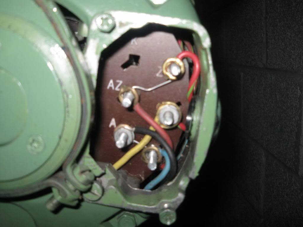
| 25 forum posts | Hi folks. I have a Myford super 7 with a Brook,Crompton,Parkinson 550w single phase motor. I wired this in to a Dewhurst reversing switch as per the wiring diagram in the Myford manual, but when I tried to start the motor the RCD in the house tripped. Upon firther inverstigation of the motor internal wiring, i see two fixed links between terminal AZ-Z and A-T. So, my question is are these links meant to be there? Or are they here because the previous owner had a 3 pin plug wired directly into the motor and the only way of starting it was by switching the wall socket on? I have attached a pic of the terminals for clarity.
Scott Edited By Scottmk1 on 13/03/2013 15:31:35 |
| Clive Hartland | 13/03/2013 17:41:43 |
 2929 forum posts 41 photos | My Myford book shows Crompton as having. A and AZ as the running windings, and Z and T as the starting windings. Your pic. does not look like that at all. I venture that the motor is wired 3phase, someone will be along soon to correct the problem. Clive
|
| Scottmk1 | 13/03/2013 18:17:35 |
| 25 forum posts | Hi Clive, thanks for your reply. I'm not sure about it being wired for 3-phase. If I connect a single phase supply to the motor (Neutral to terminal A & Live to terminal AZ) the motor runs. |
| john fletcher 1 | 13/03/2013 18:59:38 |
| 893 forum posts | From memory,and hope I've have got it correct. Remove both links. Connect Live to terminal 1 on the Dewhurst switch Neutral to terminal 3. Connect terminal A on the motor to 5, AZ to 7, the other two terminals on the motor to 2 & 6 either way round. The motor might run opposite direction to that shown on the switch, if so exchange 2 & 6. By the way Dewhurst switches a notoriuos for bad arcing contacts,could that be the trouble, they are not designed to be used as ON/OFF switches inspite of them being fitted to Myford lathe.Better get a proper motor starter with Green/ Red push buttons and no volt release. Used the starter as ON/Off and the Dewhurst for direction only. Best of luck and if you need any more help call out. Ted |
| john fletcher 1 | 13/03/2013 19:00:18 |
| 893 forum posts | From memory,and hope I've have got it correct. Remove both links. Connect Live to terminal 1 on the Dewhurst switch Neutral to terminal 3. Connect terminal A on the motor to 5, AZ to 7, the other two terminals on the motor to 2 & 6 either way round. The motor might run opposite direction to that shown on the switch, if so exchange 2 & 6. By the way Dewhurst switches a notoriuos for bad arcing contacts,could that be the trouble, they are not designed to be used as ON/OFF switches inspite of them being fitted to Myford lathe.Better get a proper motor starter with Green/ Red push buttons and no volt release. Used the starter as ON/Off and the Dewhurst for direction only. Best of luck and if you need any more help call out. Ted |
| Scottmk1 | 13/03/2013 19:13:55 |
| 25 forum posts | Hi, thanks for your input. Your memory seems to serve you correct and its just the links that are causing me trouble. i will remove them and try again. Scott |
| Clive Hartland | 13/03/2013 21:00:43 |
2929 forum posts 41 photos | I agree with Teds wiring of the Dewhurst switch. My pic. shows no links attached. Is there no diagram under the cap over the connection box? Clive |
| JohnF | 13/03/2013 21:08:25 |
 1243 forum posts 202 photos | Hi Scott, I have some PDF dos of the wiring diagram from the Myford handbook if you message me with your email I will send them to you. John |
| Robbo | 13/03/2013 22:26:02 |
| 1504 forum posts 142 photos | Ted has got it right. Simply all you need to do is remove the links, they are there for direct one-way connection. and then wire to the Dewhurst in accordance with the diagram and Ted's instructions. Also, do as Ted says and fit a decent on/off switch such as a Crabtree on-line (DOL) or an NVR switch between the Dewhurst and the power supply.
Phil |
| Scottmk1 | 13/03/2013 23:03:51 |
| 25 forum posts | Clive, there is no wiring diagram under the cover of the motor, so I will just remover the links and see how it goes. John, I have the original Myford book, but a PDF copy would be great for reference, will message you my email address. Thanks to everyone else for their input/help. I will get hold of a dol most likely and use that. The Dewhurst switch I have is new and unused so it ould be a shame to ruin it. |
| Robbo | 14/03/2013 14:18:57 |
| 1504 forum posts 142 photos | If you go for a DOL, you will find it is built for 3-phase use, with 3 connectors, 3sets of coils etc. where the inputs are L1, L2, L3 and the outputs are A, B, C. It will still be fine with single phase and just needs a link from say input L2 to output A. Then connect your input to L1 (line) and L3 (neutral) and take the outputs from B (line) and C (neutral). If you already know this, apologies, just thought it might be worth noting in advance. The above is the scheme recommended by Tubal Cain in his "Model Engineer's Handbook", and is what I have used several times. Phil |
| Scottmk1 | 14/03/2013 15:01:51 |
| 25 forum posts | Hi Phil, thanks for the advice, no it wasnt something I was fully aware of already so your advice is welcome.
Scott |
| Scottmk1 | 14/03/2013 21:05:46 |
| 25 forum posts | Just as an update, wiring the motor/switch combo as per the instructions worked once the two links were removed. Now I just need to get the on/off starter as advised. |
Please login to post a reply.
Magazine Locator
Want the latest issue of Model Engineer or Model Engineers' Workshop? Use our magazine locator links to find your nearest stockist!
Sign up to our Newsletter
Sign up to our newsletter and get a free digital issue.
You can unsubscribe at anytime. View our privacy policy at www.mortons.co.uk/privacy
Latest Forum Posts
- *Oct 2023: FORUM MIGRATION TIMELINE*
05/10/2023 07:57:11 - Making ER11 collet chuck
05/10/2023 07:56:24 - What did you do today? 2023
05/10/2023 07:25:01 - Orrery
05/10/2023 06:00:41 - Wera hand-tools
05/10/2023 05:47:07 - New member
05/10/2023 04:40:11 - Problems with external pot on at1 vfd
05/10/2023 00:06:32 - Drain plug
04/10/2023 23:36:17 - digi phase converter for 10 machines.....
04/10/2023 23:13:48 - Winter Storage Of Locomotives
04/10/2023 21:02:11 - More Latest Posts...
- View All Topics
Support Our Partners


Shopping Partners
Subscription Offer

Latest "For Sale" Ads
- Reeves** - Rebuilt Royal Scot by Martin Evans
by John Broughton
£300.00 - BRITANNIA 5" GAUGE James Perrier
by Jon Seabright 1
£2,500.00 - Drill Grinder - for restoration
by Nigel Graham 2
£0.00 - WARCO WM18 MILLING MACHINE
by Alex Chudley
£1,200.00 - MYFORD SUPER 7 LATHE
by Alex Chudley
£2,000.00 - More "For Sale" Ads...
Latest "Wanted" Ads
- D1-3 backplate
by Michael Horley
Price Not Specified - fixed steady for a Colchester bantam mark1 800
by George Jervis
Price Not Specified - lbsc pansy
by JACK SIDEBOTHAM
Price Not Specified - Pratt Burnerd multifit chuck key.
by Tim Riome
Price Not Specified - BANDSAW BLADE WELDER
by HUGH
Price Not Specified - More "Wanted" Ads...
Get In Touch!
Do you want to contact the Model Engineer and Model Engineers' Workshop team?
You can contact us by phone, mail or email about the magazines including becoming a contributor, submitting reader's letters or making queries about articles. You can also get in touch about this website, advertising or other general issues.
Click THIS LINK for full contact details.
For subscription issues please see THIS LINK.
Digital Back Issues


Donate

 Register
 Log-in
Model Engineer Magazine
- Percival Marshall
- M.E. History
- LittleLEC
- M.E. Clock

ME Workshop
- An Adcock
- & Shipley
- Horizontal
- Mill

Subscribe Now
- Great savings
- Delivered to your door

Pre-order your copy!
- Delivered to your doorstep!
- Free UK delivery!
All Forum Topics > Manual machine tools > Myford wiring