Forum sponsored by:

Schedule of the TB6560-V2 stepper control card
| Svarven | 20/02/2013 18:50:49 |
 35 forum posts 8 photos |
Hi
Bertil |
| John Stevenson | 20/02/2013 19:43:11 |
 5068 forum posts 3 photos | Bertil, Sorry but saying red card is not specif enought. There are two cards out there, both with the TB6560 chips on and both red.
One has just a single parallel port socket and one has the parallel port socket with a serial port to the side of it.
Both red but both different animals. Any chance of a picture or link ?
If you haven't bought this then a word of warning to only operate these at 20 to 24 volts MAX as they easily burn out. they are not the best cards on the market. |
| Svarven | 20/02/2013 20:12:06 |
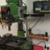
35 forum posts 8 photos | This is the controller card.
|
| Svarven | 20/02/2013 20:57:42 |
35 forum posts 8 photos |
|
| John Stevenson | 20/02/2013 21:41:54 |
5068 forum posts 3 photos | OK, Mine came with a CD with the wiring on it.
need to look it out tomorrow. |
| Chris Shelton | 21/02/2013 00:00:31 |
 92 forum posts 46 photos | Here is a link to a website showing connection details. http://whatisacnc.com/driver-board/tb6560/
HTH
|
| Svarven | 21/02/2013 16:56:35 |
35 forum posts 8 photos |
Thanks |
| Les Jones 1 | 21/02/2013 17:10:10 |
| 2292 forum posts 159 photos |
Hi Svarven, Les. |
| Svarven | 21/02/2013 17:27:49 |
35 forum posts 8 photos |
I must be blind, because I just only find scematics for the blue card at that link.
(or my bad english)
|
| Les Jones 1 | 21/02/2013 17:37:02 |
| 2292 forum posts 159 photos |
Hi Svarven, Sorry Svarven, This information is for the blue board not the red board which you require. Les. Edited By Les Jones 1 on 21/02/2013 17:51:38 |
| Svarven | 21/02/2013 20:14:58 |
35 forum posts 8 photos | Yes but that is not the same card. See my pic above. Maybee its the same configuration of the 15 pin, but im must be sure. |
| Svarven | 27/02/2013 18:07:18 |
35 forum posts 8 photos | John S have you looked at you cd?
Bertil |
| John Stevenson | 27/02/2013 19:01:06 |
5068 forum posts 3 photos | Yes, can't find it but looking inside the tiny drag engraver it's fitted to it's not a red board anyway.
Have you tried emailing the seller of the red board on ebay for a manual, they usually will give you a link prior to purchase |
| Svarven | 27/02/2013 20:27:46 |
35 forum posts 8 photos | Yes John i have , but have not get any answer from the seller.
Bertil |
| Olaf | 19/03/2013 22:38:03 |
| 2 forum posts | Hello, i do own the same red Controller card TB6560 V2 as on the picture from Svarven. And i do need some more information too (DIP Switches, PINOUT). Do anyone hase any further Informations about the board? Thanks in Advance! Greetings Olaf |
| Olaf | 23/03/2013 13:35:26 |
| 2 forum posts | I the meantime i have got some more Informations. FYI Control signal interface PIN Func Explain 1 EN Enable control signal 2 STEPX X Pulse signal 3 DIRX X Direction signal 4 STEPY Y Pulse signal 5 DIRY Y Direction signal 6 STEPZ Z Pulse signal 7 DIRZ Z Direction signal 18-25 GND GND 10 L1 Input limit interface 1 11 L2 Input limit interface 2 12 L3 Input limit interface 3 13 L4 Input limit interface 4 14 RLY Relay control signal 15 L5 Input limit interface 5 18 GND GND 19 GND GND 20 GND GND 21 GND GND 22 GND GND 23 GND GND 24 GND GND 25 GND GND The drive using six DIP switch to setting current, segments, decay Mode The current is better to closed to the motor rated current. T1 T2 current ON ON 20%*3.5A OFF ON 50%*3.5A ON OFF 75%*3.5A OFF OFF 100%*3.5A Segments Settings When M1 = off, M2 = off, drive segments number is 1,1.8 ? step angle motor turning circle, the whole step = 200 steps / rev. When M1= OFF, S4 = ON,1.8 ? step angle motor turning circle, the whole step = 3200 steps / rev. M1 M2 Segments ON ON 1/8 OFF ON 1/16 ON OFF 1/2 OFF OFF 1 Decay Mode Rapid decay is better when motor has a high speed. D1 D2 Decay Mode ON ON Rapid decay OFF ON 50%Rapid decay ON OFF 25%Rapid decay OFF OFF Slow decay |
| Royston | 01/04/2013 16:48:12 |
| 1 forum posts | Hi This is my first post but my be of help. I have the same card, I am running mach3 on XP, my pin/port settings are:- Motor output X axis, enabled, step pin 2, dir pin 3, dir low x, step low y. y axis, enabled, step pin 4, dir pin 5, dir low x, step low y. z axis, enabled, step pin 6, dir pin 7, dir low x, sep low y. Card dip settings :- All three axis are the same D1 on D2 on M1 on M2 on T1 on T2 off The three motors work ok. I need help with the relay output. The relay light comes on with some settings when Mach3 is 'Reset' and goes out with other settings but I am unable to get any output from the terminals. Royston |


Please login to post a reply.
Magazine Locator
Want the latest issue of Model Engineer or Model Engineers' Workshop? Use our magazine locator links to find your nearest stockist!
Sign up to our Newsletter
Sign up to our newsletter and get a free digital issue.
You can unsubscribe at anytime. View our privacy policy at www.mortons.co.uk/privacy
Latest Forum Posts
- *Oct 2023: FORUM MIGRATION TIMELINE*
05/10/2023 07:57:11 - Making ER11 collet chuck
05/10/2023 07:56:24 - What did you do today? 2023
05/10/2023 07:25:01 - Orrery
05/10/2023 06:00:41 - Wera hand-tools
05/10/2023 05:47:07 - New member
05/10/2023 04:40:11 - Problems with external pot on at1 vfd
05/10/2023 00:06:32 - Drain plug
04/10/2023 23:36:17 - digi phase converter for 10 machines.....
04/10/2023 23:13:48 - Winter Storage Of Locomotives
04/10/2023 21:02:11 - More Latest Posts...
- View All Topics
Support Our Partners


Shopping Partners
Subscription Offer

Latest "For Sale" Ads
- Reeves** - Rebuilt Royal Scot by Martin Evans
by John Broughton
£300.00 - BRITANNIA 5" GAUGE James Perrier
by Jon Seabright 1
£2,500.00 - Drill Grinder - for restoration
by Nigel Graham 2
£0.00 - WARCO WM18 MILLING MACHINE
by Alex Chudley
£1,200.00 - MYFORD SUPER 7 LATHE
by Alex Chudley
£2,000.00 - More "For Sale" Ads...
Latest "Wanted" Ads
- D1-3 backplate
by Michael Horley
Price Not Specified - fixed steady for a Colchester bantam mark1 800
by George Jervis
Price Not Specified - lbsc pansy
by JACK SIDEBOTHAM
Price Not Specified - Pratt Burnerd multifit chuck key.
by Tim Riome
Price Not Specified - BANDSAW BLADE WELDER
by HUGH
Price Not Specified - More "Wanted" Ads...
Get In Touch!
Do you want to contact the Model Engineer and Model Engineers' Workshop team?
You can contact us by phone, mail or email about the magazines including becoming a contributor, submitting reader's letters or making queries about articles. You can also get in touch about this website, advertising or other general issues.
Click THIS LINK for full contact details.
For subscription issues please see THIS LINK.
Digital Back Issues


Donate

 Register
 Log-in
Model Engineer Magazine
- Percival Marshall
- M.E. History
- LittleLEC
- M.E. Clock

ME Workshop
- An Adcock
- & Shipley
- Horizontal
- Mill

Subscribe Now
- Great savings
- Delivered to your door

Pre-order your copy!
- Delivered to your doorstep!
- Free UK delivery!
All Forum Topics > CNC machines, Home builds, Conversions, ELS, automation, software, etc tools > Schedule of the TB6560-V2 stepper control card