Forum sponsored by:

Speed Increaser
| Roderick Jenkins | 17/06/2011 14:32:43 |
 2376 forum posts 800 photos | Has anybody made Dick Stephen's speed increaser as supplied by Hemmingway? Any comments on construction?
Rod |
| John Haine | 17/06/2011 15:00:45 |
| 5563 forum posts 322 photos | I think it reverses direction so your mill needs a reversible motor. |
| Roderick Jenkins | 17/06/2011 18:22:46 |
2376 forum posts 800 photos | John, Thanks, I am aware of that. I wondered, when I put an inverter drive on the mill, what on earth use reverse would be. Now I know  cheers, Rod |
| John Stevenson | 17/06/2011 20:32:21 |
 5068 forum posts 3 photos | Rod, I looked at this a while ago and wasn't very impressed on the design. Basically it's a 3:1 increaser and runs in reverse as mentioned before but it only has one planet wheel running round the sun with no top bearing support, in fact it relies on the one bottom bearing. The result is that the planet wheel wants to push the sun out of mesh. Dick hold the ring gear and drives the planet with the sun as driven, this gives the 3:1 increase in reverse. If he had driven the ring hear, held a pair of planets and taken the drive off the sun he would have got an increase of 4:1 in the correct rotation, this using all the same parts but one extra planet gear. Plus the ability to provide a top bearing for support. I can't comment on Hemingway's drawings which are usually good but the original MEW drawings leave a lot to be desired, for instance the sun wheel is missing and if you make all the spindle parts and come to assemble them, they are longer than the space allows. John S. |
| Roderick Jenkins | 18/06/2011 14:47:34 |
2376 forum posts 800 photos | John, Thanks for those comments. I bought the kit and started manufacture without really thinking about it but have now become uncomfortable with the design. Whilst it may be fine for engraving I do not think it is robust enough for a 3mm endmill. The drawings seem fine but could really do with a cross-section. There are some 3D views but these do not show the critical internal workings. I'm drawing up the cross-section myself and will give serious consideration to your suggested improvements. many thanks, Rod Edited By Roderick Jenkins on 18/06/2011 14:49:21 |
| John Stevenson | 18/06/2011 15:00:36 |
5068 forum posts 3 photos | Here is the original design as a sketch. 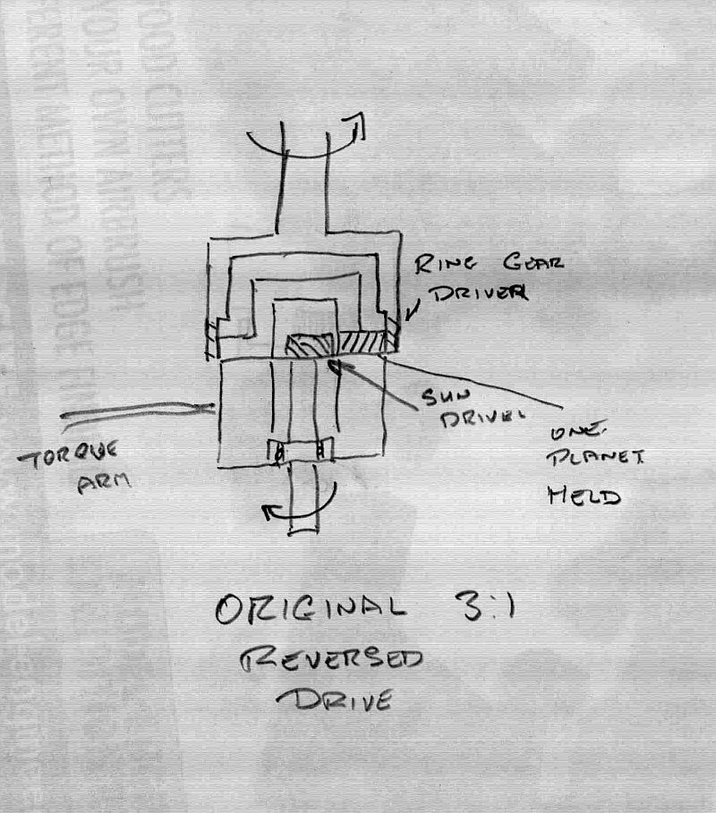 As you can see it relies on just the bottom bearing for support and this is just a generic ball race, not a high precision bearing. There is no top support at all. Now using the same parts, this can be achieved. 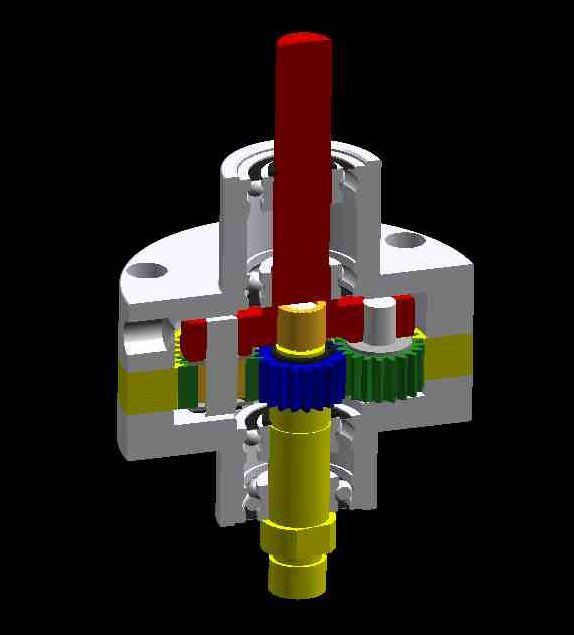 © 2005 John Stevenson. Two bearing at the top for good support and the input, red, drives the planet wheel carries, planet wheels in green. Ring gear, yellow sandwich is held and the output is by the blue sun wheel, again caried by two bearings and having an oilite top bush inside the red carrier. The carrier need thickening up a tad as it's too thin at the bottom, drawing error. This design will give 4:1 increase in the same direction. John S. |
| Pat | 18/06/2011 15:29:22 |
| 94 forum posts 1 photos |
Hi Rod
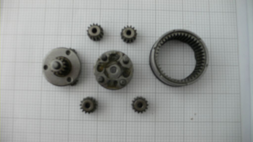
I also had reservations about the torque that could be transmitted. So I started to look for a planetary gear box to act as a source of gears. I have now got the gear box guts of a Bosch industrial grade battery drill. Got these as a gift as the chucks had been wrecked and the retaining screw head chewed up.
The gears are designed to transmit torque. The gears and bearings show no sign of wear and the input to out put ratio is around five - difficult to hold the bits together with out the plastic case!
The planet gear cluster has four pinions and the over all diameter is 37mm. I will photograph the bits but may have difficulty posting so there could be a delay!
 Phew!
Reagrds - Pat
Edited By Pat on 18/06/2011 15:41:42 |
| Roderick Jenkins | 19/06/2011 17:14:06 |
2376 forum posts 800 photos | 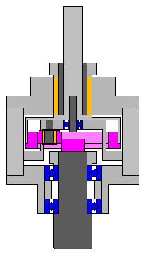 I've created this cross section from the Hemingway drawings, the pink bits are the gears. Clearly some tweaking will be required on manufacture to get the gears meshing properly. I'll make it according to the drawing and see how it goes. I am a bit nervous about locating the ball bearings using only Loctite but we'll see. It can always be dismantled and modified later. Rod Edited By Roderick Jenkins on 19/06/2011 17:15:05 |
| Michael Horner | 17/10/2012 14:29:42 |
| 229 forum posts 63 photos | Hi Rod How's your build of the speed increaser coming along? I am trying to draw up plans to build one along the lines John S suggested. HPC do a 72 tooth ring gear with a 60mm OD and Dick Stephens suggested a 16 tooth sun gear should be ok giving a ratio of 5.5:1. The intention is to drive it with a KX3 so the top speed could be excess of 20,000 RPM. This gives me concerns about the oilite bush getting enough oil to stop it burning up! I am thinking of using 3 planets to take the strain off the sun gear. Just working out the machining sequence. Cheers Michael |
| Roderick Jenkins | 17/10/2012 20:17:11 |
2376 forum posts 800 photos | Michael, It's put to one side for the moment. My thoughts are following Michael's comment above and using my Arrand spindle which is good for 8000rpm. Keep us informed of progress. best wishes Rod |
| Michael Horner | 17/10/2012 21:36:33 |
| 229 forum posts 63 photos | Hi Michael I have seen the thread you mentioned but couldn't find it on a revisit. I was put off by the bulk of the design. But your mention of it has triggered the thought of use the body of the bearing housing as a pulley which will run at spindle speed, take an elastic band out to an outrigger shaft with small and large pulley then another elastic band back to to the new spindle so long as I can get a ratio 4:1 I will get my target speed of 20,000 rpm. Probably want a gaurd for the elastic bands cause i'll bet they'll sting if they snap and hit you! Hi Rod
if the above will work I think it will be the way to go, the gears for my other design were going to cost £76 I've probably got the materials in my scrap box Cheers Michael. |
| John Stevenson | 18/10/2012 01:28:57 |
5068 forum posts 3 photos | My design got shelved as the price of the high speed 400 Hz spindles are now really affordable and the plus side is they are so quiet.
Even at 4:1 increase you still have to run the mill flat out and get all attendant noise and vibration with it.
I'm running a 24,000 rev spindle at half speed and the noise of the cutter in the material is the greatest noise.
So far the longest it has run cutting a job was an engraving of the Mother in law which took 11 hours to cut, mind you she is a rather large lady......... |
| Stub Mandrel | 18/10/2012 20:24:33 |
 4318 forum posts 291 photos 1 articles | A bit of lateral thinking - I made a toolpost drill/mill by fitting the planetary gearbox out of a broken portable drill into a steel housing. If you took the internals out of such a gearbox and fitted them the other way around... Note these gearboxes are two-stage, so you could just use one stage. Neil |
Please login to post a reply.
Magazine Locator
Want the latest issue of Model Engineer or Model Engineers' Workshop? Use our magazine locator links to find your nearest stockist!
Sign up to our Newsletter
Sign up to our newsletter and get a free digital issue.
You can unsubscribe at anytime. View our privacy policy at www.mortons.co.uk/privacy
Latest Forum Posts
- *Oct 2023: FORUM MIGRATION TIMELINE*
05/10/2023 07:57:11 - Making ER11 collet chuck
05/10/2023 07:56:24 - What did you do today? 2023
05/10/2023 07:25:01 - Orrery
05/10/2023 06:00:41 - Wera hand-tools
05/10/2023 05:47:07 - New member
05/10/2023 04:40:11 - Problems with external pot on at1 vfd
05/10/2023 00:06:32 - Drain plug
04/10/2023 23:36:17 - digi phase converter for 10 machines.....
04/10/2023 23:13:48 - Winter Storage Of Locomotives
04/10/2023 21:02:11 - More Latest Posts...
- View All Topics
Support Our Partners


Shopping Partners
Subscription Offer

Latest "For Sale" Ads
- Reeves** - Rebuilt Royal Scot by Martin Evans
by John Broughton
£300.00 - BRITANNIA 5" GAUGE James Perrier
by Jon Seabright 1
£2,500.00 - Drill Grinder - for restoration
by Nigel Graham 2
£0.00 - WARCO WM18 MILLING MACHINE
by Alex Chudley
£1,200.00 - MYFORD SUPER 7 LATHE
by Alex Chudley
£2,000.00 - More "For Sale" Ads...
Latest "Wanted" Ads
- D1-3 backplate
by Michael Horley
Price Not Specified - fixed steady for a Colchester bantam mark1 800
by George Jervis
Price Not Specified - lbsc pansy
by JACK SIDEBOTHAM
Price Not Specified - Pratt Burnerd multifit chuck key.
by Tim Riome
Price Not Specified - BANDSAW BLADE WELDER
by HUGH
Price Not Specified - More "Wanted" Ads...
Get In Touch!
Do you want to contact the Model Engineer and Model Engineers' Workshop team?
You can contact us by phone, mail or email about the magazines including becoming a contributor, submitting reader's letters or making queries about articles. You can also get in touch about this website, advertising or other general issues.
Click THIS LINK for full contact details.
For subscription issues please see THIS LINK.
Digital Back Issues


Donate

 Register
 Log-in
Model Engineer Magazine
- Percival Marshall
- M.E. History
- LittleLEC
- M.E. Clock

ME Workshop
- An Adcock
- & Shipley
- Horizontal
- Mill

Subscribe Now
- Great savings
- Delivered to your door

Pre-order your copy!
- Delivered to your doorstep!
- Free UK delivery!
All Forum Topics > Workshop Tools and Tooling > Speed Increaser