Forum sponsored by:

My skeleton clock
The skeleton clock has come alive!
| Sam Stones | 14/05/2011 03:37:02 |
 922 forum posts 332 photos | Hello to all you clock lovers,
This may be an opportune time to follow up on all my previous (clock) postings, having been delayed due to several health issues. With the help of a very kind friend who sent me a couple of helical balance springs to try, I was able to set my `John Stevens’ clock ticking under power. It's only been abobut 35 years in the making!? If you care to view my John Steven skelton clock album (in about page 13), it may help you to see what I'm talking about.
An 80lb (36kg) breaking strength fishing line transfers power from the barrel of the main spring up to the fusee. With the fusee half full of line, the clock has been running for more than 48 hours. During the interim period, I have learned a few things about the balance spring, and was very careful to curl the ends of the balance spring so that they lined up with the anchor points. This has turned out to be most important, otherwise the adjacent spring coil can rub against the anchor bracket (or cock), creating a damping effect. My earlier attempts did just that, while visually the springs wobbled instead of breathing.
The once-on-the-hour bell is quite distinct and puts a smile on my good wife’s face whenever it rings. It was necessary to `invent’ an additional spring which would `catch’ the bell hammer and stop it from yammering several times when it struck the bell. There is one snag however. The clock ticks (beats) too fast, taking only 28 minutes between bell tinkles, and for the minute hand to traverse one hour of the chapter ring. Upon closer inspection of the balance spring I found that the spring wire is about 37% larger in diameter. In terms of wire stiffness, this is a whopping 4 times greater (diameter raised to the fourth power) than my previous calculations. So I made yet another trip to see my friend with a music shop, and bought some more guitar strings. I have mentioned in other threads that, in abandoning a flat section spring for a round wire, I calculated that I needed a wire diameter of 0.2mm (0.008"). It just so happens that this is the smallest diameter of guitar strings. Lucky me! So now it’s back into the garage to try a couple of new spring-winding ideas. Despite lots of help from ME contributors, my previous attempts at winding 0.2mm diameter wire around a 4mm mandrel by hand, have been thwarted by several issues. None the least being varying helical pitch. I have also been warned several times that making a helical balance spring is one of the hardest tasks in clock making and repairing. But failure at this point means that the clock would be almost useless. Perhaps I should have started with making the spring, or gone the easier way and used a pendulum, with a falling weight for the power. No, not for me!!! Regards to all,
Sam
|
| Sam Stones | 14/05/2011 03:54:36 |
922 forum posts 332 photos | Sorry about the spelling errors. I tried to get back via `Edit', but something crashed.
Regards,
Sam |
| ady | 14/05/2011 10:48:24 |
| 612 forum posts 50 photos | my previous attempts at winding 0.2mm diameter wire around a 4mm
mandrel by hand, have been thwarted by several issues. None the least
being varying helical pitch. Spareys "the amateurs lathe" uses his lathe for spring winding. There's a piccy around page 190 depending on the reprint. The lathe is put into the screwcutting gear closest to the pitch of the spring. It's also worth mentioning that the first man to make a really accurate hand made clock spent most of his life at it, took 6 years on the final prototype and went into recorded history. So you've set yourself a bit of a challenge... |
| Sam Stones | 15/05/2011 00:57:05 |
922 forum posts 332 photos |
Thanks for your response ADY,
If you like that kind of history, which I certainly do, I would indeed recommend reading "The Illustrated Longitude" by Dava Sobel. If I remember correctly, it was also made into a documentary for TV.
For reference to my previous threads, please insert as appropriate - the words `Balance' or `Spring' or `HobbyMat' into the `Keywords' column.
As mentioned in one or other of these previous threads, the lathe I’m using (a HobbyMat with a constant mesh leadscrew) is not very friendly in the screw-cutting or spring winding department. I shall therefore continue winding the chuck by hand, with a couple of changes noted below.
Before I do, I must reiterate warnings (especially those of other ME readers) about the dangers of winding springs on a lathe. DO NOT DO IT UNDER POWER! To reduce the risk of an accident, turn off the power supply to the machine. Addressing my current issue of variable helical pitch, I note some of my previous efforts as follows :- For strength purposes, I made sure that there was a nicely polished fillet radius at the corner of the mandrel where it steps down from 6.4mm (1/4") to the 4mm working diameter. Working in the plastics industry for about 50 plus years, has made me particularly conscious of failures due to sharp corners and consequential notch sensitivity. Inadvertently, with the anchor hole for the wire drilled through at the 6.4mm diameter, (again for strength, but more especially to limit deflection), I have probably allowed the wire to slide and roll over the fillet radius down to the 4mm diameter, introducing an unwanted twist to the wire. I used gravity to tension the wire which required a feed/guide pulley some 200mm from the tool post. I'm unsure if the wire should be fully controlled as it wraps around the mandrel or if it should be free. With very limited workshop (garage) facilities, there is very little I can do to set up the best method.
What I propose to do is drill another wire anchor-hole through the 4mm section so that the wire only makes contact with the mandrel at this smaller diameter. Using a length of timber placed horizontally and fastened to the lathe tool post, I will move the feed/guide pulley so as to extend the free length of the wire to its maximum of 1 metre.
It was a surprise to find that the guitar string (made in America), was 1 metre long.
They may get to complete metrication eventually, says he tongue in cheek.
 Best regards,
Sam
Edited By Sam Stones on 15/05/2011 00:57:35 Edited By Sam Stones on 15/05/2011 00:59:20 |
| ady | 15/05/2011 01:20:04 |
| 612 forum posts 50 photos | As far as longitude is concerned. I lived it for seven years. Only one guy I ever met knew more than me, a P&O guy who was a delight to know and learn from. As far as springs are concerned, I would say that you have to experiment and one day you will find some of the secrets they never recorded on paper I would also agree with you 100% that wood offers solutions that metal cannot provide in this particular scenario. EDIT There's a solution which the maths guys cannot provide, just like the new years day wave. It's basic maths, BUT they lack the ability...no, WE(as human beings) lack the ability to see solutions unless the data gets put directly in front of us. Edited By ady on 15/05/2011 01:27:38 Edited By ady on 15/05/2011 01:31:06 |
| ady | 15/05/2011 01:35:30 |
| 612 forum posts 50 photos | The new years day wave isn't even properly recorded on the rogue wave page in wiki pedia. Daupner?? wtf is that?? If you put 'new' into the link above you get a very restricted hit. It's connected with global warming. They don't like it when we can prove that they actually know diddly. Edited By ady on 15/05/2011 01:40:47 |
| ady | 15/05/2011 01:44:23 |
| 612 forum posts 50 photos | ...and do I give a rats bum that they know about global warming or anything else? I think not. I just love engineering and am deeply humbled by the amazing achievements of people 60 years ago, my forefathers. |
| Sam Stones | 15/05/2011 02:08:21 |
922 forum posts 332 photos | Thanks for your comments ADY,
Are you working late or early?
I too love engineering, AND anything else (within my limits) which I find to be technically challenging. I shall now mull over your words, especially who `they' are.
In Australia, we have a gumn't. Would these be the sort of people to which you refer?
Back to thought about clocks |
| ady | 15/05/2011 02:21:03 |
| 612 forum posts 50 photos | Welllll...I wouldn't really worry about "them" if you put me on the spot. Just do what you enjoy and are good at. Maybe, one day, you will astonish us all with the simplicity of your answer to a problem we all thought was complicated.(us AND them) |
| Sam Stones | 15/05/2011 02:43:22 |
922 forum posts 332 photos | Hello again ADY,
I imagine you are working very late, since its almost midday here.
If only I knew how to write about stuff in just a few words. Then I could expect to be rewarded for being simplistic.
What I found humbling, as I entered this field of clock making, was how clocks were made centuries ago.
I became especially impressed with the patience of individuals who spent years just making arbors or gears, or other parts (by hand), while trying to scrape a crust for their large families.
But this isn't getting our Sunday housework done.
Regards to all,
Sam
Edited By Sam Stones on 15/05/2011 02:45:26 |
| ady | 15/05/2011 03:33:49 |
| 612 forum posts 50 photos | I'm also preaching from a backgear position as far as lathes are concerned. I believe that the hobbymats are a bit speedy for screwcutting, 250rpm or sumfink like that. This would also apply to spring winding. If you can find a lathe with working backgear, or a fine feed reduction system for the hobbymat, then a whole new world will open up for you. Edited By ady on 15/05/2011 03:34:37 |
| Sam Stones | 15/05/2011 05:04:29 |
922 forum posts 332 photos |
Hi ADY, I have enjoyed our little sojourn, or dare I say pontification? But . . . in a not very simplistic response, I must confess to being spoiled by an old treadle engineer’s lathe which my father bought for me before I left school in 1950, my six-year toolmaking apprenticeship, several toolroom years on a Myford Super7, and many more years owning my own ML7 with many trimmings including a Norton box (please refer to my album `Stop gaps'). All this followed by countless hours on a few other lathes chucked in for good measure, I’d have to agree with you about using a back gear. As for something which changes the ratio ‘tween t’chuck speed and t’leadscrew, that’s out of the question. So, I’m stuck wi’thobbymat, and the generosity of its owner, coupled with some bits o’ wood. I shall, no doubt, be back with more on a clock which keeps better time. Best regards, Sam PS I’m now obliged to complete today’s housework tomorrow. |
| NJH | 16/05/2011 10:01:21 |
 2314 forum posts 139 photos | Sam Fantastic - you've got it running! After your long project you must be pleased - it is certainly a very handsome clock. Not accurate?- well never mind this will enable you to continue " fiddling" with it whilst admiring its elegant proportions and beautiful finish. It will provide a source of conversation and an interesting stimulus as you work out the solution. OK so its not too good if you are relying on it to make an important appointment but, hey, if you need to do this you will find a much better clock in your local £1 shop! Best wishes Norman |
| Sam Stones | 17/05/2011 02:19:22 |
922 forum posts 332 photos |
Thanks for your compliments about my clock, Norman. As for its appearance and the technical aspects, I think we owe a lot to the late John Stevens for his ME article c.1972. On several occasions, I have seen the sensibility of sections of his design, and how they relate to clock-making practices of yesteryear. There are not many tasks left for me to do and, with a fair amount of time to spare now my health issues are in check, I am certainly prepared to fiddle to get the clock nearer to its potential.
On a very limited budget, I’m having to make do with what I can lay my hands on. What’s left (if I can urge enough heat from my gas torch), involves a few stages of fabrication and silver soldering. For example, I’m making the shaft of the winding key from a short length of half inch diameter brass bar. This, if my ideas work, will be sculpted to try to match the clock’s design. The cross piece of the key has been marked out on the flat section of a cheap brass hinge, and will be silver soldered to a slot in the shaft. In Australia, we have a chain of hardware super stores called Bunnings. It was to our `local’ Bunnings yesterday that I had to make two trips to pick up the hinge. What I brought home on the first trip was ideal for my purposes. That was until I placed a magnet onto it. The bl . . y thing was plated steel. After all these years you would think that I’d know better. Faced with a limited range of tools, I pondered about the simplest way to form the (4.9mm x 4.9mm) square hole in the key which matches the square end of the fusee arbor. So, at the end of the key shaft I have sawn and filed a shape which forms two opposite sides of the square hole. 
I’ve also pondered whether to reinforce this end of the key shaft with a steel ferule, thus increasing the key’s (burst) strength. Despite the clock having a maintaining mechanism, I have visions that if the key were to break mid-wind, the clock could suffer damage too. The resultant (ferule) diameter needs to be quite slim to sensibly match the rest of the clock, and would best be a press fit over the brass. Alternatively, I’m tempted to use Araldite. After getting the balance spring right, the last test will be making a case, for which I have had heaps of helpful suggestions. Although appearing to be lesser challenging than other aspects of the clock, the case has to satisfy several functions, non-the-least being dust exclusion while allowing it to `breath’ during the wide temperature fluctuations. Australia can become quite warm during the day, while getting pretty cool at night. There can also be an `impressive’ show when it comes to dust. Regards to all, Sam |
| Sam Stones | 17/05/2011 03:11:09 |
922 forum posts 332 photos |
While waiting for a bit of sunshine to warm up the garage, I thought I’d post a quick picture to go along with my last posting.
 It’s more about coming up with an acceptable shape while dodging the hinge screw-holes, and to maximise the size of the key handle. The brass hinge was actually coated with a clear varnish (probably polyurethane), which helped a little with marking out.
We're getting a bit of midday sunshine, so after lunch I'll get to work with saw and file.
Sam |
| Terryd | 17/05/2011 06:05:23 |
 1946 forum posts 179 photos | Posted by ady on 15/05/2011 01:20:04: As far as longitude is concerned. I lived it for seven years. Only one guy I ever met knew more than me, a P&O guy who was a delight to know and learn from........................... Hi Ady, Dava Sobel's book 'Longitude' mentioned by Sam, isn't really about longitude as such. It is about Harrison's endeavours to produce the perfect chronometer in order to be able to measure longitude and win a prize of £20,000. It is a smallish book and an easy read. Harrison was an son of a carpenter and became one himself and beat the great minds of the day who were looking for astronomical solutions to the longitude problem - You'd enjoy that, him beating 'them'. He started clockmaking by building a wooden clock which needed no lubrication, a real lateral thinker. It took him many more than 6 years to perfect the chronometer through at least 5 different prototypes. I think it took longer for the government to award the prize following his success. By the way, a Harrison No 5 was the chronometer found by Del boy in 'Only Fools and horses' which won him the millions at that final auction. Enjoy Terry |
| Terryd | 17/05/2011 10:03:34 |
1946 forum posts 179 photos | Hi Sam, Sorry not to have PMd earlier, glad to hear that your health has improved. Great news about the clock working, now spend th4e next 20 odd years perfecting .Any chance of a video, on YouTube perhaps, to show all of us the fruits of your labours (and make us all jealous at the same time). A simple Mobile phone vid would be excellent. Regarding helical springs, I'm probably teaching granny to suck eggs,' but I make mine on the lathe as you good self and make them with closed coils. Having done rough calculations I then cut the correct number of coils plus about 4 and then stretch the spring to size, leaving 2 at each end closed. I then grind the end of the spring flat using the mandrel to carry the spring at 90 deg. to the wheel. I make mine under power as I can get down to 30 rpm and use folded leather in a large pair of flat nosed pliers (actually jewellers draw plate pliers) to grip and tension the wire and direct it by eye. I only use short lengths of wire to prevent the possibility of it coiling around anything important at the free end! Best regards, Terry |
| Sam Stones | 18/05/2011 04:49:06 |
922 forum posts 332 photos |
Thanks for your response Terry, I hope you won't mind, but I’ll address your ideas in a moment. First, I have to say that last night while watching TV, the clock was ticking away merrily in the background albeit at twice its intended speed. From the vicinity of the clock, there was a sudden `clatter’. Actually, clatter is a bit too strong a word because the noise was that of a pin dropping. There was a noticeable change of clock beat too, although it was still running but at a slower rate. When I investigated, the clock was ticking but with less obvious vigour by way of the balance wheel and escapement. Peering closer, I could see that the taper pin (actually a piece of sewing needle) was missing from the bottom of the spring. This pin is 0.82mm diameter, has a flat along one side, and is wedged into the balance spring collet to attach the spring to the balance wheel arbor. Here's the collet. 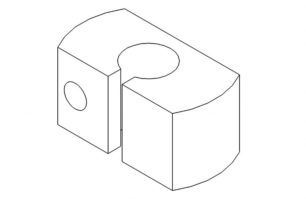
Although the clock was still ticking, it was clear that being loose, the spring could not offer the same stiffness, and was perhaps rubbing against itself or slopping around in the collet hole. Some of this terminology can be reinterpreted, but I won’t go down that path. As expected, the clock eventually stopped, but the experience gave me additional confidence that the escapement was not as tight as it once was. Previously, I had needed to relieve each mating bit of the escapement to ensure `freedom without shake’, as the books tell us.
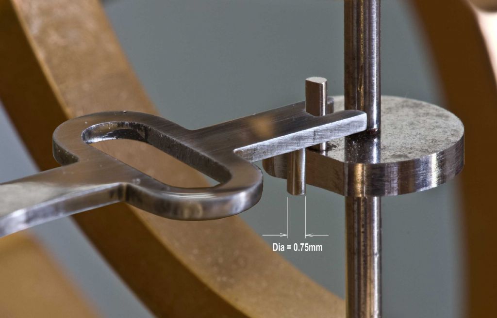
Here's the lever escapement. The 0.75mm pin in this picture is the guard pin, not the 0.82mm pin which grips the spring wire in the collet which would normally appear on the 1.5mm diameter arbor (ie. the main `shaft' running top to bottom in this view).
Terry, I really appreciate your comments, as I do for the many others who have contributed to my threads. I think too, that you’ve revealed another couple of issues about spring winding. I must, however reiterate that I’m using a borrowed Hobbymat lathe, and presume that it will run at about 250rpm as suggested by ADY. So, while back-gear would be handy, I have to stick with hand winding. What you have done is draw my attention to (close-coil) winding a just sufficient length of wire onto the mandrel to make one complete spring. I’ve been using up most of the 1 metre length of guitar string in the hope of achieving a useable length of spring. The hardest part has been controlling the spring once it has been cut free. Previous attempts have resulted in coils flying everywhere, including wrapping themselves around each other. With the wire being so fine 0.2mm (0.008"), the task is really tricky. The ends of the spring are finished differently to those you describe, and don’t need to be ground flat. The top end of the spring curls inwards slightly to engage with the balance spring stud (cock). The bottom end curls inwards to within 1.2mm of the balance wheel arbor. In some respects, allowing the weight of the balance wheel (etc.) To hang on the spring, pulls the close-coiled spring apart, while reducing the load on the balance wheel arbor’s bottom bearing.
Finally, and I hope you will understand, I'm well equipped to take still photographs in real close-up, but stepping into movies is something I'm not very keen to do, unless there is enough optical resolution.
Phew!
 Regards,
Sam
Edited By Sam Stones on 18/05/2011 04:56:20 Edited By Sam Stones on 18/05/2011 05:00:20 |
| John Olsen | 18/05/2011 07:56:18 |
| 1294 forum posts 108 photos 1 articles | Hi Sam, Have you considered making up a handle to go in the end of the spindle. I have one somewhere for my Unimat. It has a simple expanding mandrel to fit the left hand end of the spindle. Anything complex, like I expect spring winding would be, would require an assistant to turn the handle steadily when requested, but then one doesn't do these jobs every day. You do seem to manage to get some very nice pictures of the works, what are you using? I have a bellows attachment that lets me fill the frame with a flies wing, or would if the darn fly would stay still. regards John |
| Sam Stones | 18/05/2011 09:27:35 |
922 forum posts 332 photos |
Hi John, Thanks for your post. I can say that I haven’t given making a handle much thought, probably due to the fact that having disposed of my workshop, I’m limited with having suitable materials to hand, and the lathe is not my machine. Also, as you indicate, the handle would not get used too often. A bit of laziness would also enter into it. I should give it more thought, because it’s not easy pushing the small three-jaw chuck round backwards by hand, although the wire is under tension and being guided over the mandrel so I can use both hands. Photographically, and thanks for your compliment, I use a Canon EOS 300D Digital, and used some of the funds from selling my workshop, to buy a 100mm Ultrasonic macro which, as you would appreciate allows some close up work. Like you, I have a bellows (Novoflex). This couples the lens electronically to the camera, so auto focus and aperture are taken care of should this be necessary. With a good Manfrotto tripod for rigidity, I take charge of focus and aim for the usual one third/two thirds to determine what should be sharp and what can be allowed to drop out of focus. Although the rules suggest we avoid the smallest and the largest lens apertures. So, for extreme close-ups, I generally use the minimum aperture and ignore what aberrations may creep in. Close up photography is perhaps my favourite field, and is almost always `still life’. My hands aren’t steady enough to grab those instant nature shots. I just look at the achievements of others with admiration. With my type of close-ups, there’s usually no rush, and I can take all the time I like so long as the kitchen bench is not required by my dear wife.
I also bought Adobe Photoshop CS3, which is an absolute delight to use, and lets me `cheat' in several ways.
My earlier photographic experiences were involved in burning up lots of energy taking weddings and the like. In those days I was a Leica man (35mm of course), with a pretty smart darkroom for B&W processing. Ah! those were the days.
 Now it's time to relax and watch a bit of TV. The skeleton clock is silent for the time being.
Regards,
Sam Edited By Sam Stones on 18/05/2011 09:31:03 |

Please login to post a reply.
Magazine Locator
Want the latest issue of Model Engineer or Model Engineers' Workshop? Use our magazine locator links to find your nearest stockist!
Sign up to our Newsletter
Sign up to our newsletter and get a free digital issue.
You can unsubscribe at anytime. View our privacy policy at www.mortons.co.uk/privacy
Latest Forum Posts
- *Oct 2023: FORUM MIGRATION TIMELINE*
05/10/2023 07:57:11 - Making ER11 collet chuck
05/10/2023 07:56:24 - What did you do today? 2023
05/10/2023 07:25:01 - Orrery
05/10/2023 06:00:41 - Wera hand-tools
05/10/2023 05:47:07 - New member
05/10/2023 04:40:11 - Problems with external pot on at1 vfd
05/10/2023 00:06:32 - Drain plug
04/10/2023 23:36:17 - digi phase converter for 10 machines.....
04/10/2023 23:13:48 - Winter Storage Of Locomotives
04/10/2023 21:02:11 - More Latest Posts...
- View All Topics
Support Our Partners


Shopping Partners
Subscription Offer

Latest "For Sale" Ads
- Reeves** - Rebuilt Royal Scot by Martin Evans
by John Broughton
£300.00 - BRITANNIA 5" GAUGE James Perrier
by Jon Seabright 1
£2,500.00 - Drill Grinder - for restoration
by Nigel Graham 2
£0.00 - WARCO WM18 MILLING MACHINE
by Alex Chudley
£1,200.00 - MYFORD SUPER 7 LATHE
by Alex Chudley
£2,000.00 - More "For Sale" Ads...
Latest "Wanted" Ads
- D1-3 backplate
by Michael Horley
Price Not Specified - fixed steady for a Colchester bantam mark1 800
by George Jervis
Price Not Specified - lbsc pansy
by JACK SIDEBOTHAM
Price Not Specified - Pratt Burnerd multifit chuck key.
by Tim Riome
Price Not Specified - BANDSAW BLADE WELDER
by HUGH
Price Not Specified - More "Wanted" Ads...
Get In Touch!
Do you want to contact the Model Engineer and Model Engineers' Workshop team?
You can contact us by phone, mail or email about the magazines including becoming a contributor, submitting reader's letters or making queries about articles. You can also get in touch about this website, advertising or other general issues.
Click THIS LINK for full contact details.
For subscription issues please see THIS LINK.
Digital Back Issues


Donate

 Register
 Log-in
Model Engineer Magazine
- Percival Marshall
- M.E. History
- LittleLEC
- M.E. Clock

ME Workshop
- An Adcock
- & Shipley
- Horizontal
- Mill

Subscribe Now
- Great savings
- Delivered to your door

Pre-order your copy!
- Delivered to your doorstep!
- Free UK delivery!
All Forum Topics > Clocks and Scientific Instruments > My skeleton clock