Forum sponsored by:

Steam turbine, which of the design is effective??
| Jens Eirik Skogstad | 23/04/2011 09:39:11 |
 400 forum posts 22 photos | Dear all folks, i am planning to make own steam turbine with reduction gear, all will be ball beared. Which of the turbine wheel is effective when we are talking about the same turbine wheel diameter with difference construction and use same steam pressure: Reaction-, pulse- or Tesla turbine?
I saw the Jensen and Wilesco steam turbine has difference construction from other such as Saito steam turbine and Proteus turbine. Will theJensen- and Wilesco turbine be useful for modelboat?
Come with the advice from you about steam turbine  |
| wotsit | 23/04/2011 18:41:03 |
| 188 forum posts 1 photos | Hi, Jens, There may be some useful information to help you in the following thread on this forum Good luck Keith |
| Richard Parsons | 24/04/2011 09:07:17 |
 645 forum posts 33 photos | Jens - Do not be put off by the thread above. Have a go but be aware 1. Small turbines are greedy for steam. Successful units tend to use waste steam. 2. Small turbines are FAST. I had one go up to 2 million RPM before it disintegrated. The aircraft Gyros run at about 14-16,000 rpm. They run in a partial vacuum because the air is sucked into them, but NO power is taken from them (except overcoming friction). 3. Their efficiency is abysmal. I was after power output. 4. Both Stumphs and DeLavals are not so difficult to make if you make the correct tooling. 5. You will have 3 or 4 BIG problems a. Bearings, you will ‘fry/curry’ them by the dozen, But things have moved on in the past 20 years, b. Reduction gears – I often got the dreaded ‘Grrrrr-wheee-poof’. As the gear stripped, the turbine ran away and disintegrated!. c. The physical strength of the turbine wheel. Calculate the internal stresses on your wheel at 2,000 rpm, 20,000 rpm, 200,000 rpm and finally at 2,000,000 rpm. It is horrendous. d. Nozzle design. In these sizes remember you are well down into the boundary layer. 6. Beware there are many claims and conspiracy theories about Tessla’s turbines and the rest of his works BUT that is enough of that. Go for reaction turbines, I did try an expansion turbine, a lot of work and I could not get it to spin. I did but the clearances were too large. I am afraid my note books vanished some years ago If you succeed please write it up. Turbines are such simple machines and well worth working on. I will watch this space for signs of success. Good luck Dick |
| Jens Eirik Skogstad | 26/04/2011 22:56:00 |
400 forum posts 22 photos | Hi, also not simple to get enough power out of the steam turbine to run the model boat?
The vanes must be curved to make "jet stream" in other side of the turbine wheel?
I am planning to make the turbine wheel at 1-1/4" diametre with 25-30 vanes.. but not sure.. The ball bearings are at 4 mm d x 9 mm D x 4 mm W.
I saw at the Karstein turbine wheel, the vanes are mounted at side instead top of the turbine wheel, how are the effect compared to a turbine wheel with vanes mounted in top of the turbine wheel.
Better to machine the vanes in the turbine wheel (with milling machine and rotary table) or mount the loose vanes on the turbine wheel and solder the parts of turbine wheel togheter? |
| Jens Eirik Skogstad | 01/05/2011 00:05:34 |
400 forum posts 22 photos | Thanks for the answer from you..
I searched the info about the model steam turbine ,and i found the book in PDF file. It is a book "Model steam turbines" by H. H. Harrison. I downloaded the book from Library of the university of California. The book is well written about the model steam turbine and how to calculate and make the steam turbine.
|
| Jens Eirik Skogstad | 04/05/2011 19:47:05 |
400 forum posts 22 photos | Hi folks!
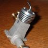
I has maked the steam turbine after the drawning of Elmer Verburg steamturbine with ball bearing.
Then i took the test with difference oils in the bearings.
Here are the tests of oils and measured revolutions per minute:
Work pressure= Mobil ESP 5W-30 / Air tool oil / Diesel oil (fuel for diesel engine as lubricant)
1 bar= 4700 / 13230 / 17600
1.5 bar= 6200 / 17900 / 25700
2 bar= 11400 / 21660 / 31500
2.5 bar= 15500/26340 / 36700
3 bar= 18600 / 28800 / 41800
As i can see the ball bearing get less friction with diesel oil as lucricant, it is sensitive for jet stream from nozzle. With high revolution above 15000, i can feel there are enough torque when trying to stop the turbine shaft.
I can think: With less friction means less waste of the steam and fuel for heating the boiler.
What is your meaning about the oil/rpm to a "fixed" working pressure?
Edited By Jens Eirik Skogstad on 04/05/2011 19:50:30 Edited By Jens Eirik Skogstad on 04/05/2011 19:57:56 |
| Richard Parsons | 05/05/2011 12:48:03 |
645 forum posts 33 photos | Jens your results are very interesting. When I was trying to build the things one of my problems (amongst many others was) fried bearings. Some of which were from a very expensive supplier and two sets few given to me by a company which made ‘air driven’ aircraft instruments which ran at about 15,000 RPM. The best which lasted about 35 minutes total running time were made of the carbon rods from old dry batteries. The shafts were piano wire used on a Spinco ultra centrifuges. They survived three stripped primary drive gears. One of my problems is that my turbines were small (max rotor size was 50mm) so to get power which was what I was after they had to spin very fast. Best Regards Dick Edited By Richard Parsons on 05/05/2011 12:49:28 |
| Jens Eirik Skogstad | 05/05/2011 22:37:51 |
400 forum posts 22 photos | Today i tested with steam with good results
 No problem with ball bearing with diesel oil, no mixed with water. The turbine ran above 35000 rpm with good torque. When i removed the heat of the boiler, the steam turbine was still running up to 2 minutes before the pressure was dropped of.. there was enough torque. No problem with ball bearing with diesel oil, no mixed with water. The turbine ran above 35000 rpm with good torque. When i removed the heat of the boiler, the steam turbine was still running up to 2 minutes before the pressure was dropped of.. there was enough torque.I am uploading the movie of my turbine in Youtube..
ready to see later..Here is the plan of the turbine: http://www.john-tom.com/ElmersEngines/12_turbine.pdf
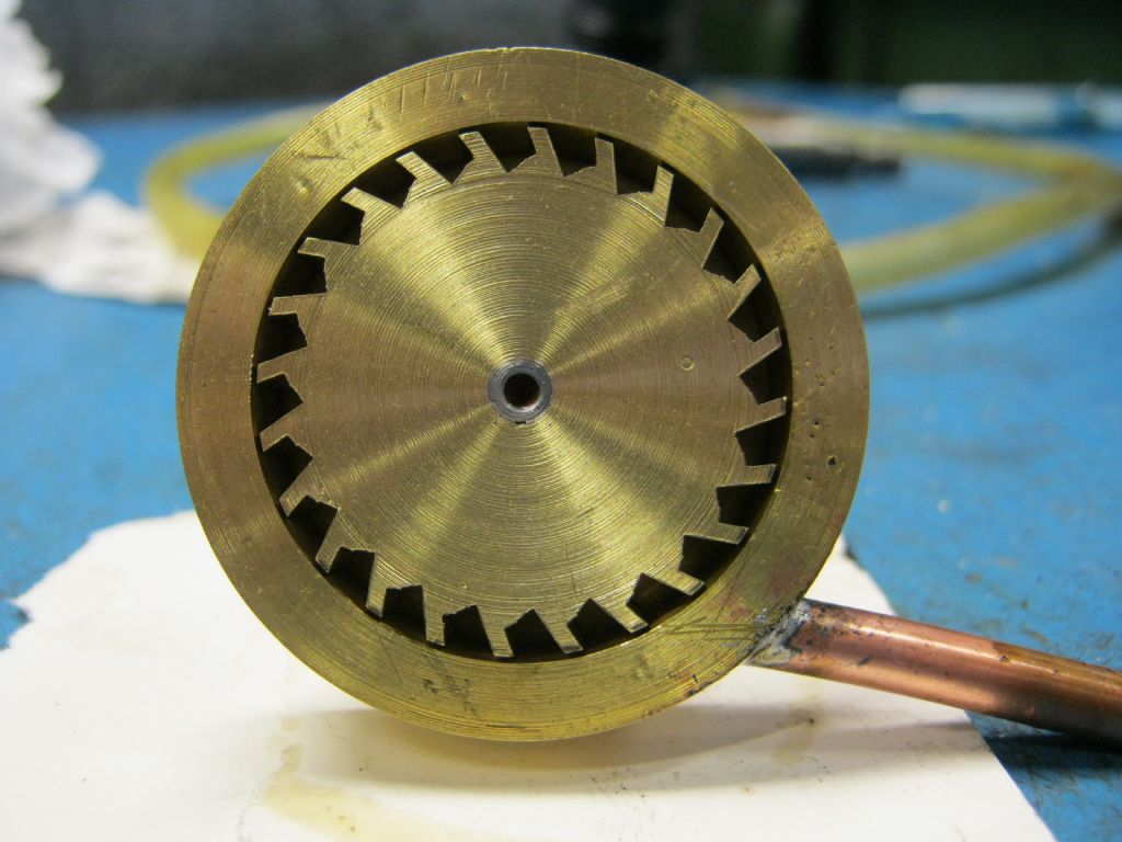
I added the ball bearing 4mm x 9mm x 4mm instead bronze bearing. The turbine wheel in brass, 5/16" thick and the wheel is near close to the turbine house, about 0,5 mm clearance. The vanes is milled with 2 mm saw cut wheel. The shaft was silverbrazed to turbine wheel before complete machining the whole turbine wheel. There is no out of balance.
Edited By Jens Eirik Skogstad on 05/05/2011 23:06:11 |
| Jens Eirik Skogstad | 05/05/2011 22:51:23 |
400 forum posts 22 photos | Here is the movie: http://www.youtube.com/watch?v=OVlh7KDxcdg Edited By Jens Eirik Skogstad on 05/05/2011 22:54:22 |
| Werner Jeggli | 08/05/2011 16:49:56 |
| 28 forum posts 6 photos | Posted by MICHAEL WILLIAMS on 08/05/2011 10:41:39: Hi , Jens : The mechanical design of your turbine with the 4mm bearings etc is quite ok and for a simple turbine I would not change it . The gas flow design of the turbine is not so good and efficiency will be much lower than it need be . It depends now on whether you want to stay with this simple design and just use it directly for your original purpose of running a model boat or whether you want to get into the more general topic of designing high performance turbines . Richard : A 50 mm turbine with only moderate steam pressure and temperature could in principle develop several horsepower outut . The main problem with small steam turbines is that it is very easy to design one where the steam goes clean through the turbine and out the other side without transfering any energy . Success is all down to creating a clean , stable very high speed jet from the nozzle and setting up the correct interaction geometry between steam jet and turbine blades . I personally would be very interested to hear about some of your experiments and perhaps all people interested in this subject would like to discuss the whole of this topic in more depth . MW .
|
| Jens Eirik Skogstad | 09/05/2011 23:01:34 |
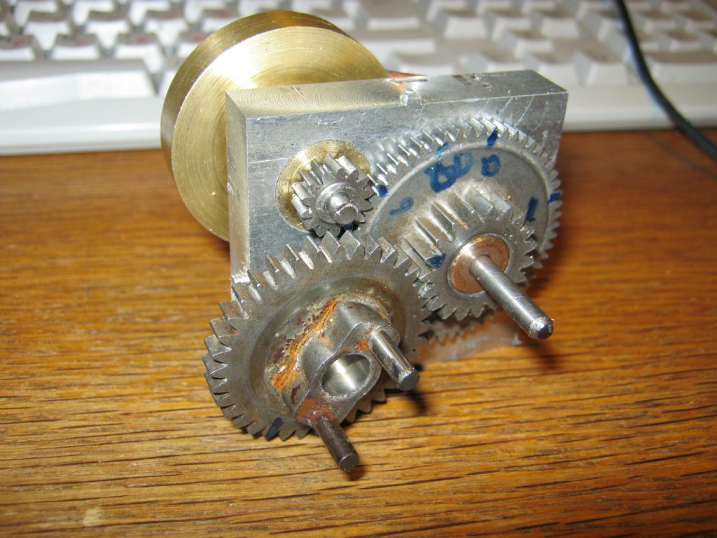
400 forum posts 22 photos | Hi, i has maked the reduction gear to steam turbine, the gear ratio is 10.2:1. But not tested before the sear set is completed and ready to run. I am planning to test the horsepower with miscellaneoud air screws and tachometer + the program "Thrust hp", then i can learn out how much effective is the rpm range and steam pressure.
 |
| ady | 09/05/2011 23:40:32 |
| 612 forum posts 50 photos | Only a guess but maybe there is a connection with inefficient small wind turbines. A chap I know had one with a single blade size of about 1.5 meters for about two years. When he took it down I asked about it, thinking the powers that be had objected but it turns out it hardly made any power at all for him, and we're in a relatively exposed windy area. He reckoned that he would need a blade of around 10 meters to make it worthwhile. His solar unit was fine, and generated a reasonable amount of energy. Soooo. If you can figure out how to make a reasonably efficient blade system for a small wind turbine perhaps this solution could be carried over to helping with small steam turbines. 2centrinos Edit: I watched the video. Inefficient or not, that's a darned kewl little bit of kit. Edited By ady on 09/05/2011 23:46:58 |
| Richard Parsons | 10/05/2011 07:36:35 |
645 forum posts 33 photos | Michael - The work I did started in the early 70s with the Stumpf type turbines. Because of limitation in machining capacity (a little Unimat SL) I was limited in sizes and materials. It sort of worked making a ‘wee-ing noise’ when running on low pressure air, but it had no power. It would stop if you looked at it cross eyed. I read everything I could find in the County Libraries –not much- I admit. But I came across the DeLaval turbine and nozzle. My early DeLaval wheels were simply slots sawn at 45° across the disk and nozzles were made using clock maker’s broaches. These disks were easier to make than the cutters for Stumps type. More by luck than judgement the blades on my second DeLaval over lapped. It looked promising especially when it disintegrated (on air). It was then I saw an illustration of a DeLaval which had its nozzle at 70° to the axel (20° to the plane of the disk). This I discovered had been done to reduce the effective velocity of the air/steam flow. I steepened the blade angle which were ‘slab sided’. As things were so small, I did not think that aerodynamic shapes would have any effect. About 1973 I had saver up enough cash for a Myford ML10 which being more rigid allowed me more scope. I also met the late Professor Chaddock and as a result I started to make curved blade rotors. I did nothing between 1974 and 1977 moving house and work etc. But in 1978 I was given an old Oscilloscope and by attaching a magnet to the turbine shaft I could measure the rotational speed of the disk. It was getting frightening, but I noticed that when I connected up the circuit I could hear the turbine slow down. I tried making annular nozzles (sort of 2 dimensional venturi with vanes in to direct the flow). I even built a 4 stage Curtis unit (never again). I was still getting less than 2-5% of the theoretical output. Or ‘louse power’ as I described it in a letter to Professor Chaddock. It all came to a stop when I came to the ‘notice’ of the ‘local authorities’. I owned a dog and my new neighbours were Moslems. They did not care but the ‘Authorities’ did and they wanted the dog to go. So for the next year or so I was involved in various legal battles with the ‘authorities’. All of which I won, but they seldom paid my costs. Their eternal excuse was that these ‘expenses’ were not in this year’s ‘budget’. These sorts of niggles rumbled on including my shed being opened (in my absence) and sealed for 2 months by ‘Elfin Safety’. This went on until I just ‘vanished’ early in this centenary. You cannot ‘buck’ city hall. I am afraid all my work notebooks and drawings from the 70s and 80’s were lost/misplaced/removed etc, but if I can get the metal I might restart work. |
| Jens Eirik Skogstad | 02/06/2011 05:43:03 |
400 forum posts 22 photos | Hi folks!
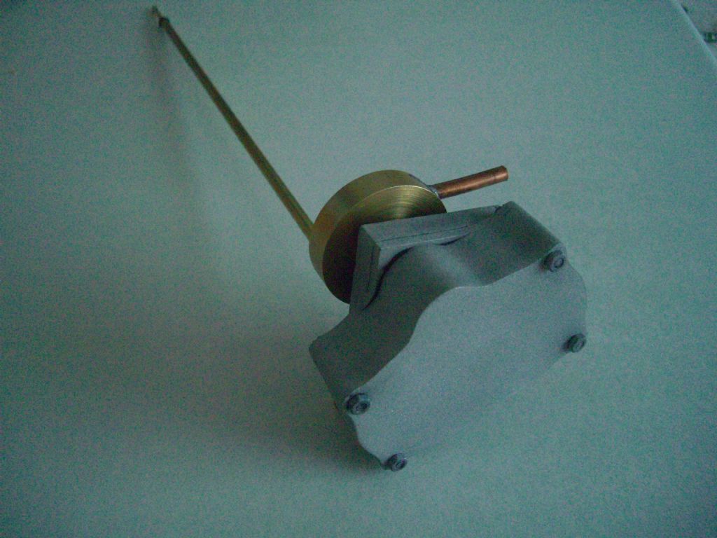
The turbine is near complete and there is propeller shaft added. It is some parts to make ready to the turbine and add the propeller. I has tested the turbine with reduction gear, there is really good torque, difficult to stop with the fingers at the propeller shaft while the turbine is running, but it is a question about start torque from zero revolution to working revolution. The reduction gear house has oil inside to keep the gear lubricated. I will rig the test stand to test the turbine with boiler connected to the turbine and the propeller in watertank.
I early post i wrote: I am planning to test the horsepower with miscellaneoud air screws and tachometer + the program "Thrust hp", then i can learn out how much effective is the rpm range and steam pressure.
I will drop this test since there is enormous torque in the turbine to test a lot of propeller in watertank.
 |
| Ian S C | 02/06/2011 13:41:50 |
 7468 forum posts 230 photos | Jens, you could drive a generator from the shaft, and load that to give the electrical power out put, ie., amps and volts. Some where I saw a test rig for a hot air engine using this system, and the generator was mounted so that the body of it was able to rotate, this was to enable the torque to measured. the little generator will be only about 50% efficient, but not as messy as propellers in water. Ian S C |
| Jens Eirik Skogstad | 02/06/2011 14:29:16 |
400 forum posts 22 photos |
Posted by Ian S C on 02/06/2011 13:41:50:
Jens, you could drive a generator from the shaft, and load that to give the electrical power out put, ie., amps and volts. Some where I saw a test rig for a hot air engine using this system, and the generator was mounted so that the body of it was able to rotate, this was to enable the torque to measured. the little generator will be only about 50% efficient, but not as messy as propellers in water. Ian S C
Ian and folks there, how can i calculate the effect by generator and volt/amper if the rpm is known? Edited By Jens Eirik Skogstad on 02/06/2011 14:42:48 |
| Ian S C | 03/06/2011 11:24:22 |
7468 forum posts 230 photos | If you know the revs, and can measure the torque, you can calculate the power in watts, or horse power; Watts = RPM x torque(inch oz) divided by 1352. Or Watts = grms x cm RPM x .00001026.
With a generator with a known load measure the amps and volts, multply these and you have watts. If you do both, you will have an idea of the efficiency of the generator, I'v spent / waisted hours with my hot air engines making graphs.
I use a home made rev counter as per James G. Rizzo's books, and an own design of brake to measure torque. Ian S C
|
| Ian S C | 04/06/2011 12:31:21 |
7468 forum posts 230 photos | The thing I would like to replace the weight hanging on the beam of my little brake is a set o f digital scales, I only want small one, but I think they are mostly used by the drug dealers, and they can afford any price the retailers ask. Ian S C |
| Jens Eirik Skogstad | 19/07/2012 05:24:00 |
400 forum posts 22 photos |
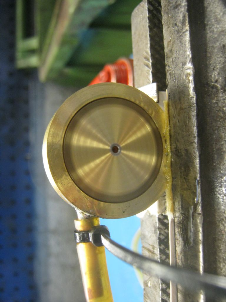
Hi all folks! I has tested the steam turbine with propeller in water under load. See the two movies here:
Edited By Jens Eirik Skogstad on 19/07/2012 05:26:09 |
| Michael Gilligan | 19/07/2012 08:27:29 |
 23121 forum posts 1360 photos | May I thank you gentlemen for posting I just happened across this thread, and have learned a lot. ... That old Model Steam Turbines book is fascinating, and your expert comments bring things nicely up to date. Anyone interested in Dynamometers might find it useful to look at Magtrol. [they generously provide PDFs of their Manuals]
MichaelG. Edited By Michael Gilligan on 19/07/2012 08:31:40 |
Please login to post a reply.
Magazine Locator
Want the latest issue of Model Engineer or Model Engineers' Workshop? Use our magazine locator links to find your nearest stockist!
Sign up to our Newsletter
Sign up to our newsletter and get a free digital issue.
You can unsubscribe at anytime. View our privacy policy at www.mortons.co.uk/privacy
Latest Forum Posts
- hemingway ball turner
04/07/2025 14:40:26 - *Oct 2023: FORUM MIGRATION TIMELINE*
05/10/2023 07:57:11 - Making ER11 collet chuck
05/10/2023 07:56:24 - What did you do today? 2023
05/10/2023 07:25:01 - Orrery
05/10/2023 06:00:41 - Wera hand-tools
05/10/2023 05:47:07 - New member
05/10/2023 04:40:11 - Problems with external pot on at1 vfd
05/10/2023 00:06:32 - Drain plug
04/10/2023 23:36:17 - digi phase converter for 10 machines.....
04/10/2023 23:13:48 - More Latest Posts...
- View All Topics
Support Our Partners


Shopping Partners
Subscription Offer

Latest "For Sale" Ads
- Reeves** - Rebuilt Royal Scot by Martin Evans
by John Broughton
£300.00 - BRITANNIA 5" GAUGE James Perrier
by Jon Seabright 1
£2,500.00 - Drill Grinder - for restoration
by Nigel Graham 2
£0.00 - WARCO WM18 MILLING MACHINE
by Alex Chudley
£1,200.00 - MYFORD SUPER 7 LATHE
by Alex Chudley
£2,000.00 - More "For Sale" Ads...
Latest "Wanted" Ads
- D1-3 backplate
by Michael Horley
Price Not Specified - fixed steady for a Colchester bantam mark1 800
by George Jervis
Price Not Specified - lbsc pansy
by JACK SIDEBOTHAM
Price Not Specified - Pratt Burnerd multifit chuck key.
by Tim Riome
Price Not Specified - BANDSAW BLADE WELDER
by HUGH
Price Not Specified - More "Wanted" Ads...
Get In Touch!
Do you want to contact the Model Engineer and Model Engineers' Workshop team?
You can contact us by phone, mail or email about the magazines including becoming a contributor, submitting reader's letters or making queries about articles. You can also get in touch about this website, advertising or other general issues.
Click THIS LINK for full contact details.
For subscription issues please see THIS LINK.
Digital Back Issues


Donate

 Register
 Log-in
Model Engineer Magazine
- Percival Marshall
- M.E. History
- LittleLEC
- M.E. Clock

ME Workshop
- An Adcock
- & Shipley
- Horizontal
- Mill

Subscribe Now
- Great savings
- Delivered to your door

Pre-order your copy!
- Delivered to your doorstep!
- Free UK delivery!
All Forum Topics > Model Boats > Steam turbine, which of the design is effective??