Forum sponsored by:

Roller bearing cages - full size
Ideas on how to make.....
| IanH | 10/04/2010 10:19:37 |
 129 forum posts 72 photos | Hi,
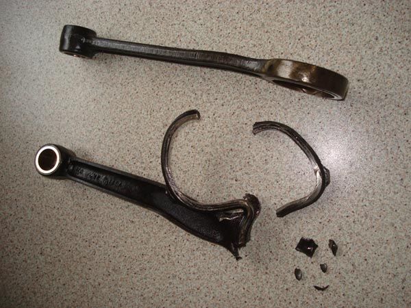
I am approaching a big end rebuild on my JAP LTOWZ engine (1000cc water cooled V Twin from the 30s). The original big end bearing was a crowded roller bearing (loads of rollers no cage) but I would like to modify this to add a light alloy cage.
The cage then is an annular ring with a series of rectangular slots to take the rollers.
Phil Irving in his seminal work "Tuning for Speed" recommends milling out the slots with a woodruffe cutter then filing the ends square but I am afraid I don't have it in me to do all that filing.
Do we have any alternative techniques for forming the cages without the filing? I have milling (manual and CNC) and turning of course.
I have wondered about making the cage in two pieces - a plain ring on one end to close off all the slots, but am not sure about how to secure it.
Ian |
| John Stevenson | 10/04/2010 10:48:00 |
 5068 forum posts 3 photos | I also make a new flywheel assembly for a JAP some years ago including new pin and bearing. I plunge cut the slots in phosphor bronze, parted it off and uses a floating washer of the same material to close the slots off.  This was a for a racing Morgan and it's still running today with no problems. John S. |
| IanH | 10/04/2010 11:03:43 |
129 forum posts 72 photos | Thanks very much for this John,
This was the idea I had in mind talking about a two piece cage but I wasn't thinking of leaving the washer floating.
Reducing the inertia by going into a lighter material might be an idea?
What did you do in terms of clearance between the cage and the crank pin and the cage and the big end sleeve for both the cage and the floating washer? I am thinking of "Tuning for Speed" where there is discussion about the cage wearing the pin away,
What clearance did you use between each roller and its slot? I am thinking that using shaped slots like this you could keep the cage off the pin and sleeve, but the washer would be free to run on the crank pin.
What do you think of giving the washer a register to held it in position on the cage - the register would need to be deeper than the end float on the big end to keep it in place.?
Lots of questions I am sorry!
Ian |
| John Stevenson | 10/04/2010 11:34:17 |
5068 forum posts 3 photos | Can't remember the clearance now, it was a few years ago, if I had to do the job tomorrow I'd probably allow 5 thou on both. The roller slots were done with a 1/4" slot drill for 1/4" x 1/4" rollers, two rows and just plunged in making the roller a snug fit but still free to move. In quite a few designs I have seen hardened washers with the ID at flywheel cheek diameter not bearing diameter so they are held fast when pressed up. I usually allow 10 to 15 thou end clearance on these old racing engines to give they a bit of bag to allow everything to line up when running. From experience trying to get everything to tight tolerances on these engines is a waste of time because they were never built to tight tolerances and they need the bit of bag to allow everything to catch up. |
| Ian S C | 10/04/2010 13:51:12 |
 7468 forum posts 230 photos | If you did decide the end washer needed to be fixed , could it be pinned to the ends of the cage pieces? The pins could be quite small, say 1.5- 2mm dia.Ian S C |
| mgj | 10/04/2010 14:45:43 |
| 1017 forum posts 14 photos | I'm a little puzzled about "all that filing"? You put the blank in a dividing head, with the potential cage aligned on the y axis. The woodruffe cutter is at centre height, and you plunge cut on the side on the cutter using the x axis. You finish with a perfectly rectangular slot with a tiddly little bevel at each end? (assuming you have chosen or made the woodruffe cutter correctly and can plunge to near centre. Too big a cutter and you'll finish with a shallow bevel). To keep the finished weight down you want it as thin as possible, which the cutter wont like, so the blank needs to be overthick on the ID, and once you have the slots, one could return it to the lathe, because one won't have taken it out of the chuck, you can size the ID and part to length. It might take as much as a minute with a needle file to square those bevels. Or have I misunderstood the set-up?. I agree, with a vertical plunge cut with a slot drill or FC3 cutter, you will have rounded semicircular ends which will have to be filed out, but not with a side cut off a woodruffe cutter. Edited By mgj on 10/04/2010 14:50:17 |
| Circlip | 10/04/2010 16:38:00 |
| 1723 forum posts | Wouldn't take much to make a "Broach" and die to take the corners out.
Regards Ian. |
| IanH | 11/04/2010 18:14:34 |
129 forum posts 72 photos | Thanks for all the information - I would love to see a sketch of the broach and die set up Ian is suggesting - any chance of this Ian?
I have sent a message to mgj to check out the woodruffe cutter proposal - I think we have different ideas of what a woodruffe cutter is although I suspect it is because the cage is relatively thick compared with its diameter rather than being a thin shell as he suggests.
At the Three Wheeler Opening run today concensus of opinion amongst the racing fraternity was to use an INA caged needle roller bearing running directly on the crank pin. The proposal for the crank pin is to go to a parallel pin with .004" interference and press it together in the hydraulic press - no tapers, no threads! I have to admit that this is tempting......
Question is whether the blade rod will be ok on its bronze bush or should this be sleeved and a crowded needle roller arrangement be put in place - it only rocks back and forth when all is said and done.
Ian |
| IanH | 17/04/2010 20:00:41 |
129 forum posts 72 photos | I think a final scheme is emerging. Moving up to a 40mm od crank pin and using a stock needle roller bearing get you up to 45mm od. If you then add in a hardened ring in the conrod eye you are looking at boring the conrod something like 0.15" over the iriginal dimension. At ths size the conrod is looking rather delicate and as this all started with a fork rod failure,,,,,
 New conrods with a bigger "big end" would be required. Plan B then is to go to a 35mm crank pin allowing me to use 42mm od needle roller bearings which can be accommodated by opening out the existing big end sleeve by only .030 on diameter. I am pretty sure the sleeve is hardened right through so this should be achievable. The od of the sleeve doesn't change so the original pattern conrods will do. If I stick with the bronze bush in the blade rod then it should be straighforward.
Ian |
| IanH | 17/04/2010 20:03:08 |
129 forum posts 72 photos | Another attempt at the photo....
 |
| Bowber | 19/04/2010 14:01:40 |
| 169 forum posts 24 photos | Oh dear
 My dad used to race an 84S on grasstrack, they were fast but a little delicate, the Jawa's always won on reliability.
A few years later and I was racing and while watching a race an 84S went past just as it blew up, peices of crank case flew into the crowd (no one was injured) I kept a lump with one of the case bolts stil in it holding 2 halves together.
Steve |
Please login to post a reply.
Magazine Locator
Want the latest issue of Model Engineer or Model Engineers' Workshop? Use our magazine locator links to find your nearest stockist!
Sign up to our Newsletter
Sign up to our newsletter and get a free digital issue.
You can unsubscribe at anytime. View our privacy policy at www.mortons.co.uk/privacy
Latest Forum Posts
- *Oct 2023: FORUM MIGRATION TIMELINE*
05/10/2023 07:57:11 - Making ER11 collet chuck
05/10/2023 07:56:24 - What did you do today? 2023
05/10/2023 07:25:01 - Orrery
05/10/2023 06:00:41 - Wera hand-tools
05/10/2023 05:47:07 - New member
05/10/2023 04:40:11 - Problems with external pot on at1 vfd
05/10/2023 00:06:32 - Drain plug
04/10/2023 23:36:17 - digi phase converter for 10 machines.....
04/10/2023 23:13:48 - Winter Storage Of Locomotives
04/10/2023 21:02:11 - More Latest Posts...
- View All Topics
Support Our Partners


Shopping Partners
Subscription Offer

Latest "For Sale" Ads
- Reeves** - Rebuilt Royal Scot by Martin Evans
by John Broughton
£300.00 - BRITANNIA 5" GAUGE James Perrier
by Jon Seabright 1
£2,500.00 - Drill Grinder - for restoration
by Nigel Graham 2
£0.00 - WARCO WM18 MILLING MACHINE
by Alex Chudley
£1,200.00 - MYFORD SUPER 7 LATHE
by Alex Chudley
£2,000.00 - More "For Sale" Ads...
Latest "Wanted" Ads
- D1-3 backplate
by Michael Horley
Price Not Specified - fixed steady for a Colchester bantam mark1 800
by George Jervis
Price Not Specified - lbsc pansy
by JACK SIDEBOTHAM
Price Not Specified - Pratt Burnerd multifit chuck key.
by Tim Riome
Price Not Specified - BANDSAW BLADE WELDER
by HUGH
Price Not Specified - More "Wanted" Ads...
Get In Touch!
Do you want to contact the Model Engineer and Model Engineers' Workshop team?
You can contact us by phone, mail or email about the magazines including becoming a contributor, submitting reader's letters or making queries about articles. You can also get in touch about this website, advertising or other general issues.
Click THIS LINK for full contact details.
For subscription issues please see THIS LINK.
Digital Back Issues


Donate

 Register
 Log-in
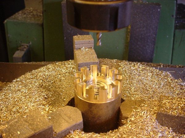
Model Engineer Magazine
- Percival Marshall
- M.E. History
- LittleLEC
- M.E. Clock

ME Workshop
- An Adcock
- & Shipley
- Horizontal
- Mill

Subscribe Now
- Great savings
- Delivered to your door

Pre-order your copy!
- Delivered to your doorstep!
- Free UK delivery!
All Forum Topics > I/C Engines > Roller bearing cages - full size