Forum sponsored by:

Very early locomotive boiler feeds
Solving the puzzle
| Jonathan Howes | 09/04/2010 16:42:13 |
| 17 forum posts 6 photos | Hi all,
I have been researching the Stephenson locomotive "Lancashire Witch" for development as a 7 1/4" gauge model for about a year now but have come up against a detail problem regarding the boiler feed pump.
This, as on many locomotives from around 1830, is driven by a crosshead coupling and the delivery is via a ram pump, so far so good.
On these early engines however the pump itself consists of typically two vertical barrels linked together with the boiler linking to the top of the uppermost barrel. Two cocks are provided, one on each barrel and I have been completely unable to find out exactly what goes on within.
Ball valves came a bit later than Lancashire Witch so the lack of space for a ball in the vicinity of each cock is not a problem, almost certainly some form of lifting plug valve is performing the same function. The problem is that any control of boiler feed seems to be almost impossible without a severe danger of hydraulic lock.
I have found three depictions of the same form of feed pump, two from drawings and one in the flesh, on "Invicta" in the Canterbury Museum but no indication of the appropriate innards. The NRM did not seem able or willing to help (although I think Invicta may have been disassembled in part for restoration) and the only other place that seems to understand really early locomotives, the Beamish museum, also presented a deafening silence.
I can post some files of the evidence to date but someone may know the answer, please wade in.
Many thanks,
Jonathan Howes. |
| KWIL | 09/04/2010 19:21:08 |
| 3681 forum posts 70 photos | Jonathan, See PM KWIL |
| Chris | 09/04/2010 21:18:17 |
| 87 forum posts 13 photos | I found the curator of the manchester museum of science and industry very helpful with my enquiries about Northumbrian. They cover the Liverpool Manchester Railway history.
He is at [email protected]
Hope this helps. I too am fascinated by the very early locos and would like to know more about your Lancashire Witch. My next project will be a 5 inch oldie (there are very few about) but a 7 sounds even more exciting.
Chris. |
| Jonathan Howes | 10/04/2010 13:48:34 |
| 17 forum posts 6 photos | Does anyone have some tips on how to add images? I would like to post two different versions of the Lancashire Witch feed pump and photographs of the unit on Invicta. Edited By Jonathan Howes on 10/04/2010 13:50:00 |
| Weary | 10/04/2010 13:59:23 |
| 421 forum posts 1 photos | This thread called Posting Photos might help.
Looking forward to seeing the pics, as I am interested in early locomotives too (though more the next 'generation')
Phil |
| Jonathan Howes | 10/04/2010 14:20:29 |
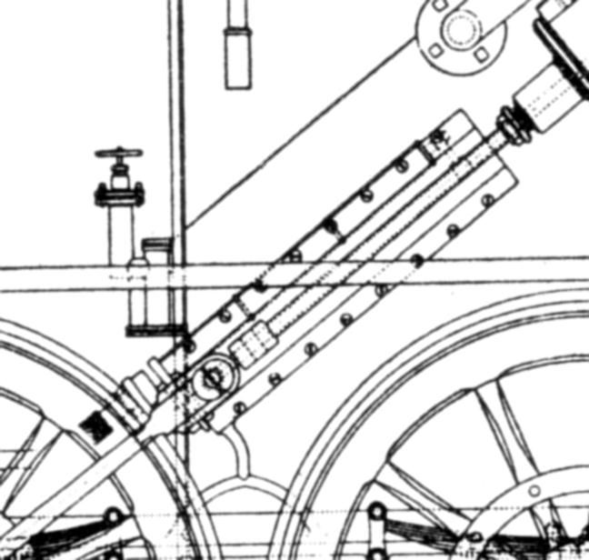
| 17 forum posts 6 photos | One from the Stephenson archive. Ho does that one knob on top control the feed without hydraulic lock? Obviously it doesn't so what is missing?
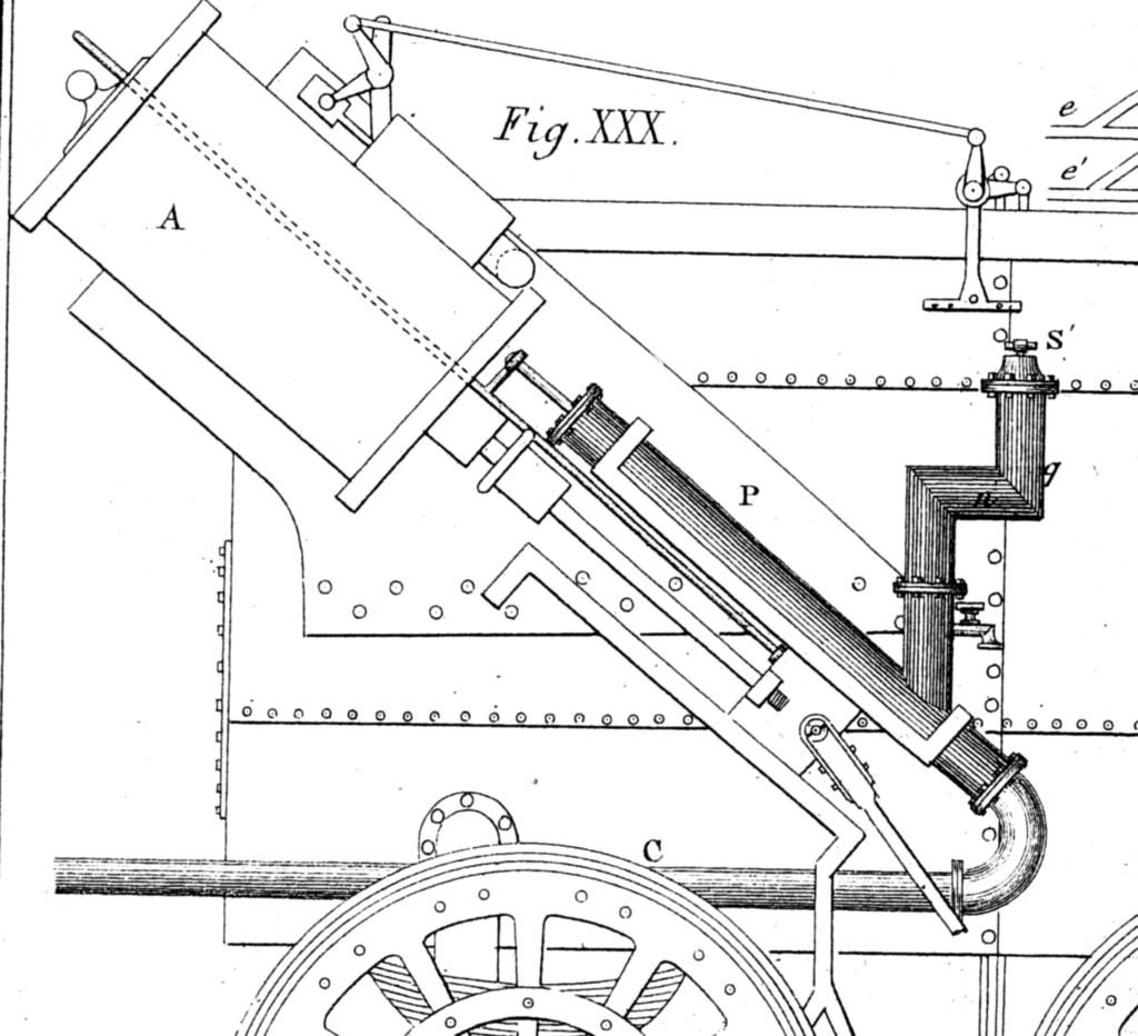
And one from the two French engineers who visited the engine at work, even more confusing:
 |
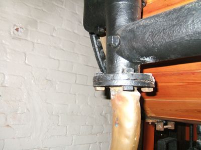
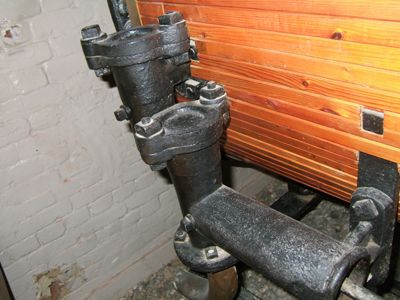
| Jonathan Howes | 10/04/2010 14:31:22 |
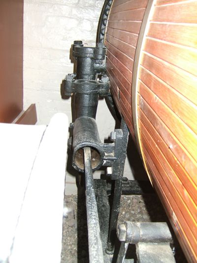
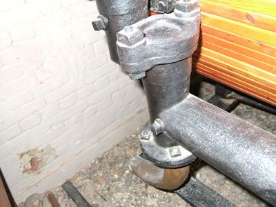
| 17 forum posts 6 photos | And four views of the Invicta unit. There seem to be two plug valves operated by square section heads implying a key in the hands of the driver, obviously regarded as a responsible job. What form of valve can be got in to the end of the ram pump to prevent its action given that there does not appear to be much room to install anything with no access cover visible?
    |
| Jonathan Howes | 10/04/2010 15:17:44 |
| 17 forum posts 6 photos | The engine was visited by the two french engineers, Coste and Perdonnet, while working on the Bolton and Leigh railway. Their description of the boiler feed goes (my translation...):
P, force pump. This draws water via a leather tube, from a barrel placed behind on a train T, and raised to the boiler by tube C.
A horizontal boiler feed tube is indicated by circle n', q (my note; this places the feed lower than on other examples).
S', the adjustable boiler feed valve. The piston rod of the force pumpis rigidly linked to the piston via a rod from the crosshead as shown in the figure.
So, still little clearer and what is that trycock doing on the vertical pipe just above the pump barrel?
|
| Jonathan Howes | 11/04/2010 10:55:32 |
| 17 forum posts 6 photos | Thanks to KWIL for sending me a drawing of the Locomotion pump. I was wondering if a three valve system was at play here. I still don't see how the feed rate is controlled however. |
| Paul White 3 | 11/04/2010 15:29:51 |
| 109 forum posts 23 photos | hi, a very interesting project . Could the answer to your question be a simple valve in the supply line that controls water into the pump? |
| Jonathan Howes | 12/04/2010 08:53:43 |
| 17 forum posts 6 photos | Paul,
This was what I was looking for at first, the problem is that the French reference (three posts back) clearly states that the valve S' in the figure is an adjustable boiler feed valve. Elswhere in the french text this is clearly stated as being convenient for the location of the driver as it projects through a platform on the side of the boiler on which the driver stands. A bit awkward here as the Stephenson drawing shows the valve and platform on the left hand side of the boiler, the French text describes (but does not show) the platform to the left and the pump/valve to the right.
From other digging, feed pipe valves do not seem to appear on locomotives until the early 1830's, LW was built in 1828 and is a very important locomotive being the first to employ expansive working of the steam, it was also the clear predecessor of the Rocket.
I am working on drawings for the model but I fear that the pump may remain "TBD" for a while yet.
Jon. Edited By Jonathan Howes on 12/04/2010 08:55:40 |
| Paul White 3 | 12/04/2010 10:19:21 |
| 109 forum posts 23 photos | Jonathan, If the valve" S "is for boiler feed, this would be a design for failure in the absence of some form of bye pass or restiction in the feed water by producing the hydraulic lock you mentioned in your earlier post ! Or am I missing something. You may have found the earliest use of feed water control. Pumps of this time had what looks like a valve lift control.
Paul. |
| Jonathan Howes | 12/04/2010 11:10:24 |
| 17 forum posts 6 photos | Paul,
You have me intrigued!
Firstly, the valve S was clearly for feed control as stated in contemporary references. I have also found a description of one of the Gurney Steam Carriages which shows a system whereby the control is to divert feedwater back to the tank, this is from before the period of the Lancashire Witch but it is possible that the valve S is there to bypass the upper clack and to allow a slug of water to oscillate between the pump and the boiler.
The valve lift control idea is interesting and is the part that intrigues me. The square headed shanks in the Invicta photographs may be just that, ie, some form of eccentric used to lift a clack open and prevent its action. Do you have any examples/drawings of valve lift control from around the right period?
Jon. |
| Ian S C | 12/04/2010 12:35:33 |
 7468 forum posts 230 photos | I'm not familia with steam engines paticulary this old, but would it be possible that the valve is in the form of a leather flap, I'v seen this in domestic supply pumps of 60-70 yr vintage and proberbly older. Ian S C |
| Paul White 3 | 13/04/2010 09:56:53 |
| 109 forum posts 23 photos | Jonathan,
Sorry no. I thought that the impression came from information in "Ahrons" but
having spent considerable time looking I can't find the reference.
I still feel that a device with one input and one output with set piston operation
can only be controlled by:- 1, restriction of supply
2, ability to hold open the feed- in valve
or 3, open outlet from cylinder to atmosphere to
prevent a vacuum being formed.
Paul. |
| Paul White 3 | 13/04/2010 09:59:05 |
| 109 forum posts 23 photos | sorry about the above posting ,I didn't type it like that !
Paul |
| Jonathan Howes | 13/04/2010 21:15:21 |
| 17 forum posts 6 photos | Paul,
Thanks for the "Ahrons" tip-off. I think the quote that you may have been searching for is in the context of the Rainhill (as opposed to Stockton and Darlington) Rocket:
"One brass feed pump was fixed between the motion bars and boiler, and worked from the crosshead. The pump had mitre valves, the lift of which was regulated by snall spiral springs. A leather hose connected the copper suction pipe with the tender."
This is actually surprisingly helpful since it shows that spiral return springs were in use, something I had assumed came later. This has clear importance for the inclined pump barrel with an in-line inlet clack valve since I was head scratching over how this could be made reliable without some form of internal spring.
Thanks again for the hint.
Jonathan.
|
| Malcolm Lippiatt | 03/08/2018 20:16:20 |
| 10 forum posts 4 photos | Hi Jonathan If you go to my thread on Lancashire Witch you can see I'm interested in creating a 3D model of The Lancashire Witch 1828 which in your thread in 2010 you stated that you were going to produce drgs of it. did you do that and if so would those drgs be available to the likes of myself. I create these loco's from drgs or/and pictures available on the net but there seem very few available on the Lancashire Witch so at the moment I'm struggling, any help would be appreciated |
| John Olsen | 04/08/2018 03:00:27 |
| 1294 forum posts 108 photos 1 articles | I see that the above discussion on boiler feeds took place some time ago, but maybe for completeness I should mention that early American locos, from about the beginning up until injectors became common, usually used crosshead feed pumps controlled by a valve in the suction line. This is quite likely a feature that they copied from their English predecessors. I have somewhere a book about early American locos that discusses this feature, and it does seem odd that they persisted with it for so long, when a simple bypass arrangement would work so much better. A pump controlled by the suction side will cavitate badly which tends to wreck the pump in short order...nevertheless they persisted with this arrangement for maybe 50 years or so. I know for instance that the Rogers 2-4-2 locomotives supplied to the New Zealand railways in 1877 came with a crosshead feedpump on each side. They were replaced with injectors quite quickly. John |
Please login to post a reply.
Magazine Locator
Want the latest issue of Model Engineer or Model Engineers' Workshop? Use our magazine locator links to find your nearest stockist!
Sign up to our Newsletter
Sign up to our newsletter and get a free digital issue.
You can unsubscribe at anytime. View our privacy policy at www.mortons.co.uk/privacy
Latest Forum Posts
- *Oct 2023: FORUM MIGRATION TIMELINE*
05/10/2023 07:57:11 - Making ER11 collet chuck
05/10/2023 07:56:24 - What did you do today? 2023
05/10/2023 07:25:01 - Orrery
05/10/2023 06:00:41 - Wera hand-tools
05/10/2023 05:47:07 - New member
05/10/2023 04:40:11 - Problems with external pot on at1 vfd
05/10/2023 00:06:32 - Drain plug
04/10/2023 23:36:17 - digi phase converter for 10 machines.....
04/10/2023 23:13:48 - Winter Storage Of Locomotives
04/10/2023 21:02:11 - More Latest Posts...
- View All Topics
Support Our Partners


Shopping Partners
Subscription Offer

Latest "For Sale" Ads
- Reeves** - Rebuilt Royal Scot by Martin Evans
by John Broughton
£300.00 - BRITANNIA 5" GAUGE James Perrier
by Jon Seabright 1
£2,500.00 - Drill Grinder - for restoration
by Nigel Graham 2
£0.00 - WARCO WM18 MILLING MACHINE
by Alex Chudley
£1,200.00 - MYFORD SUPER 7 LATHE
by Alex Chudley
£2,000.00 - More "For Sale" Ads...
Latest "Wanted" Ads
- D1-3 backplate
by Michael Horley
Price Not Specified - fixed steady for a Colchester bantam mark1 800
by George Jervis
Price Not Specified - lbsc pansy
by JACK SIDEBOTHAM
Price Not Specified - Pratt Burnerd multifit chuck key.
by Tim Riome
Price Not Specified - BANDSAW BLADE WELDER
by HUGH
Price Not Specified - More "Wanted" Ads...
Get In Touch!
Do you want to contact the Model Engineer and Model Engineers' Workshop team?
You can contact us by phone, mail or email about the magazines including becoming a contributor, submitting reader's letters or making queries about articles. You can also get in touch about this website, advertising or other general issues.
Click THIS LINK for full contact details.
For subscription issues please see THIS LINK.
Digital Back Issues


Donate

 Register
 Log-in
Model Engineer Magazine
- Percival Marshall
- M.E. History
- LittleLEC
- M.E. Clock

ME Workshop
- An Adcock
- & Shipley
- Horizontal
- Mill

Subscribe Now
- Great savings
- Delivered to your door

Pre-order your copy!
- Delivered to your doorstep!
- Free UK delivery!
All Forum Topics > Locomotives > Very early locomotive boiler feeds