Forum sponsored by:

Rina and T&K drawings
| JasonB | 10/03/2010 19:20:12 |
 25215 forum posts 3105 photos 1 articles | David
In the latest issue you have asked for comments on the drawings that acompany these two items, a few points I have spotted:
Rena Fig1. There seems to be some inconsistancy with the decimal "fractions" some are given to only two decimal places eg 2.28, one assumes this is 2 9/32 which should really be 2.281. Some are rounded down and some rounded up eg 3.345 assume 3 11/32 so 3.3438 but as you seem to be rounding to the nearest 0.0005 then 3.344 would seem right. Again 2.155 assume 2 5/32 would expect 2.156. I have no issue with printing to the nearest 0.0005" as this is what most peoples digital callipers/mics etc will read to but can it be consistant.
On both models there are radiused corners and edges, no radius is given. I know this is not a critical part of the model but would be nice to have.
Again on Rena the two side plates Fig 2 &3 are drawn to different sizes, this is possibly to keep column widths the same but I would personnaly like to see the parts to teh same "scale" even if there is a bit more air around them.
Apart from that they are fine to follow but a beginner may be trying to mark out to the odd 0.001" or so accuracy rather than 1/32nd increments.
Jason
PS should this section of the forum now be headed 2010 not 2009?? |
| David Clark 1 | 10/03/2010 21:05:09 |
 3357 forum posts 112 photos 10 articles | Hi There
Numbers are not rounded up or down but are as drawn.
Four decimal places looks stupid on say a 16.0000 dimension.
I redrew it from the pencil original and most of the dimensions were originall fractional but not all of them.
The drawings were all drawn to scale and must have got altered in size during the production process.
regards David
|
| JasonB | 11/03/2010 07:42:31 |
25215 forum posts 3105 photos 1 articles | Posted by David Clark 1 on 10/03/2010 21:05:09:
Numbers are not rounded up or down but are as drawn.
I redrew it from the pencil original and most of the dimensions were originall fractional but not all of them.
David I agree that the 000 can be left off the end but if the original sketches were in fractions why draw it 2.28 when the decimal equivalent to 2 9/32 is 2.281 or was this originally a decimal.
I can see why some of the dims were originally given as decimal, the gear ctrs and the setting out of the PCD being two examples.
Jason |
| David Clark 1 | 11/03/2010 10:17:59 |
3357 forum posts 112 photos 10 articles | Hi There
9/32 is not on the original drawing.
2.28 is the way it worked out after redrawing.
Click on drawing to enlarge.
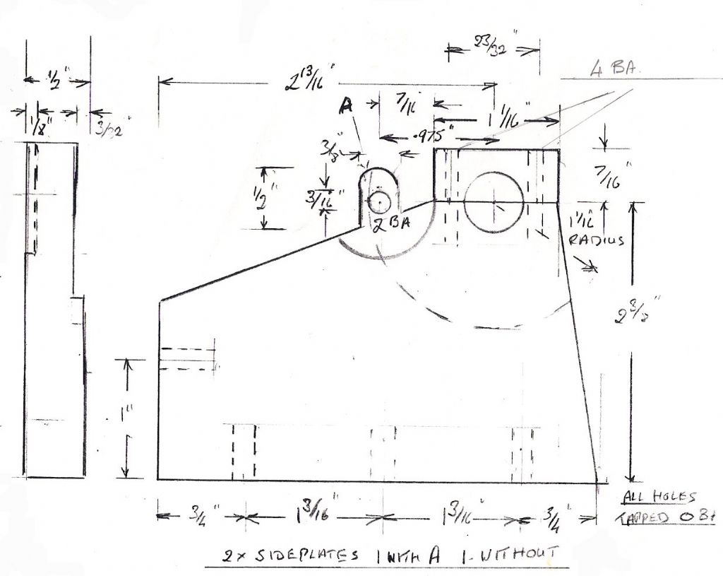 It more likely came from the .975 gear centres and was a compromise so that the radius between the gear pillar and the edge of the bearing cap was a standard size, 2.28 - 2.155 = 1/8 rad or 1/4 diameter cutter. If the average reader tried to use the original drawing, half the dimensions are missing. This is a typical example of drawings received.
regards David Edited By David Clark 1 on 11/03/2010 10:20:39 |
| Circlip | 11/03/2010 12:20:05 |
| 1723 forum posts | Now that the ubiquitous digicalips have fraction sizes as a "Feature" on some of them David, it stands to reason that it may be advantageous to leave all the "Old" (or new for that matter) dimensions in fractional sizes?? The Metric and twentyseven decimal places brigade can fiddle to their hearts content.
 Regards Ian. |
| David Clark 1 | 11/03/2010 12:46:59 |
3357 forum posts 112 photos 10 articles | Hi There
I had to redraw it so it is decimal not fractional.
I also have to make sure it fits together.
regards david
|
| JasonB | 11/03/2010 13:30:18 |
25215 forum posts 3105 photos 1 articles | Thanks for the clarification David, I can see that the 7/16" and half the bearing cap width dont add upto the gear centres and you have done the best you can with what you were given |
| mark thomas 1 | 03/04/2010 13:49:05 |
 1 forum posts 1 photos | just a query if anyone knows of any websites offering good engineering websitesdrawing |
| Jim Greethead | 16/10/2010 21:59:28 |
 131 forum posts 8 photos | I am (rather slowly) working on drawings for a metric version for my own use because I don't have any imperial tooling. In doing so, I have had to massage most of the dimensions so that they come out with 0.5 mm resolution because that is as fine as I can mark out.
I am a newbie at this and just hope it works when it is built.
Jim
|
| John Olsen | 17/10/2010 00:56:24 |
| 1294 forum posts 108 photos 1 articles | James, you don't have to rely on marking out for critical dimensions. What you can do will of course depend on what gear you have, but for instance I will quite often mark a line on the job so that I can do the initial roughing out cuts without measuring, then when getting close I start measuring and take the last cut to bring the job "exactly" to size. Of course, it will not really be exact, it will be to the tolerance of my machine and measuring equipment, plus or minus my own skill, but that is usually close enough. In our amateur work, parts that really need to be exact are usually made to suit each other, for example we might take very light cuts off a piston untl it is a nice sliding fit in a cylinder. (This does require good sharp tools, and it is often better to plan for the last cut to be a reasonble size one that gets you to exactly where you want...but that comes with practice.) For holes like David mentioned above for gears, it is quite critical to get the shaft the right distance apart to get a good mesh. For this we do not usually rely on marking out. One technique is coordinate milling where we set up and drill (preferably bore) one hole, then use the Xand Y graduations on the milling machine to move the job the exact amount for the other hole. There is much more that could be said about this of course, obviously a milling machine is needed. Another appoach uses buttons, which are small disks of accurately known size with a hole in them. Holes are drilled and tapped in the job, and used to attach the buttons, which can then be moved around by a small amount (the holes in the buttons have clearance on the screws.) Once the two buttons are the exact required distance apart, the job can be mounted in a four jaw chuck and trued to the first button. The button is removed and that hole is then bored. Then the job is reset so that the second button is true, and the boring process repeated. With typical amateur measuring equipment and gear, this should let you get holes placed to within about 0.02 of a mm or so. (Yes you experts, I know you can do better...) You can also use buttons with a milling machine, using a dial gauge on the spindle for the setting up. Buttons are easily made from ground stock, they don't have to be hardened for ordinary work. regards John |
| Jim Greethead | 17/10/2010 01:41:30 |
131 forum posts 8 photos | Thank you John, that is good advice. I have been trying a bit of that and it works well. In fact, I prefer it to the marking out method when I can use it. Holes are particularly troublesome - no matter how I try (even feeling for the lines), I can't seem to get them exact. Coordinate milling is much better despite having to accommodate the backlash.
I take your point in regard to gear spacing. On my current (and first) engine, I "fudged" it by making the shaft slightly eccentric so the spacing is adjustable. Not sure if that is good practice but it seemed to be one way around my skill limitations.
The other reason for making dimensions to 0.5 mm resolution is that the drawing looks better. And if there is no reason to specify a dimension to 0.2 or 0.1 mm, why bother.
Thanks again. This thread and the forum in general makes subscribing worthwhile.
Jim
|
| John Olsen | 17/10/2010 02:24:53 |
| 1294 forum posts 108 photos 1 articles | Hi James, The eccentric shaft, or an eccentric bush if the shaft must turn, is not an unknown idea. Better to make something that you know you can get right than to give up because it all got too hard! For the coordinate milling, you should always approach the desired position with the same direction of travel. That way the backlash does not come into it. If you have to go back on ne axis to get to another hole, go well past the desired position then come back towards it from the direction you have chosen as standard. (Generally easiest if you always work with the gradautions increasing.) Drills will wander a little, even if you do manage to get the initial centre punch mark exact. (Which is not always easy and is why you see people selling those optical ones.) This is why we bore them for more critical work.A boring bar will cut true even if the initial hole is out. Well, it will try to follow the hole a bit, but given a stiff sharp bar it should true the hole up after a few cuts. But of course you may not have a boring head for the mill...I made one of the George Thomas ones, which I find very handy Yes, where the dimension is noncritical you may as well go with something in round numbers. Especially if you can use a stock size or a stock cutter of course. David, I hope you are finding the various drawings I have sent you a little easier to work with! regards John |
| Jim Greethead | 17/10/2010 07:18:22 |
131 forum posts 8 photos | Thanks John for more excellent advice. Much appreciated.
David,
Two things:
1. Could we have a name change for this thread from Rena to Rina or a link please. The search engine does not pick up the incorrect name,
2. We seem to be missing a dimension for the cam base circle in Fig 16.
Regards
Jim
|
| David Clark 1 | 17/10/2010 11:30:35 |
3357 forum posts 112 photos 10 articles | Hi There
Thread name changed.
Will have to dig out the drawings for cam base diameter.
Not sure it is on them.
I don't think it does anything, 3/8in. will probably be fine.
regards David
|
| David Clark 1 | 17/10/2010 11:54:26 |
3357 forum posts 112 photos 10 articles | Hi There
New topic started.
See tool tips.
regards David |
| Jim Greethead | 17/10/2010 20:17:44 |
131 forum posts 8 photos | Thanks David, that was quick.
Cam base circle to top of lobe determines the lift. In retrospect, I guess I could figure it out since a lift of (valve diameter)/4 will give an opening equal to the area of the port ie. maximum required opening. I just didn't stop to think at the time.
Jim
|
| David Clark 1 | 17/10/2010 20:35:24 |
3357 forum posts 112 photos 10 articles | Hi James
Not checked yet.
Just suggested 3/8in. diameter.
Will find out when I go through articles next time.
regards David |
| John Olsen | 27/10/2010 20:58:52 |
| 1294 forum posts 108 photos 1 articles | 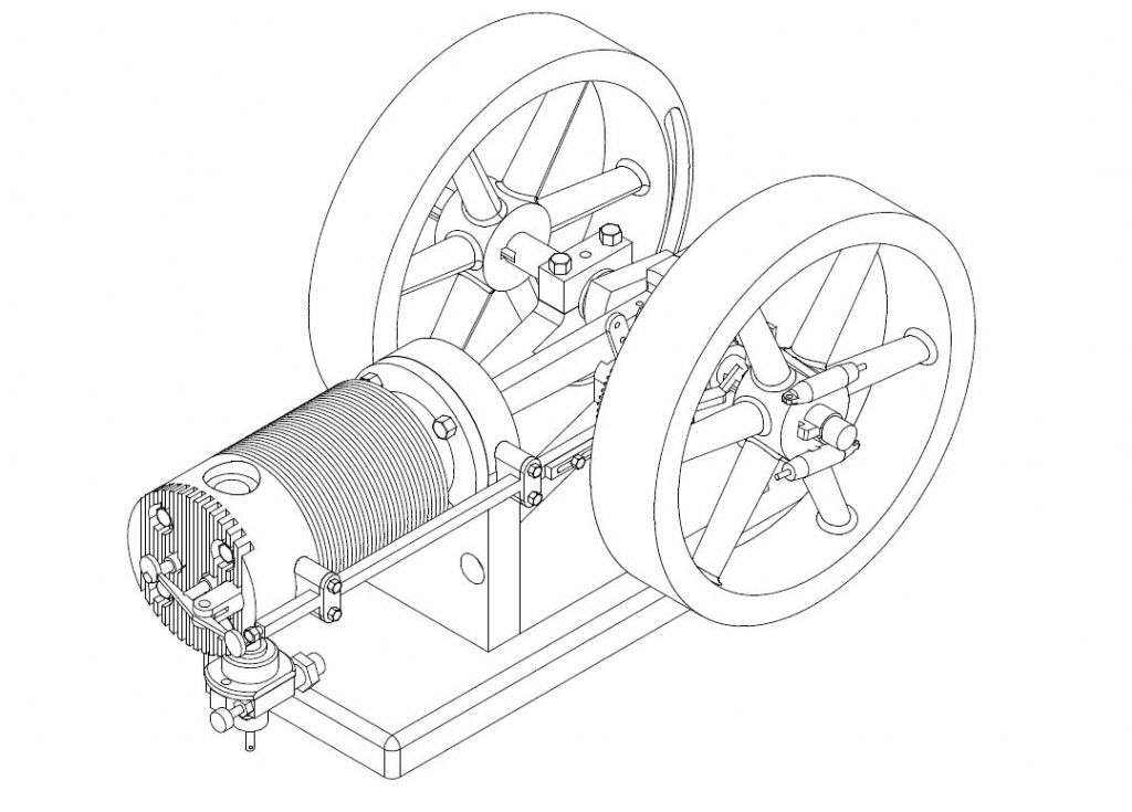 Those building this engine might find the pictures I have just posted in my album of interest. I have "built" a 3D model of all the parts presented in the articles, and assembled them into a virtual model. That allows me to easily produce general arrangement drawings in either standard projections or Isometric. I have converted a few examples into jpg and uploaded them. David, it would be really nice if we could upload pdf files as well as jpg, that way people would be able to see this "model" in a form where they can rotate to different views, zoom in, hide parts that are obscuring internal detail, and so on. regards John Edited By John Olsen on 27/10/2010 20:59:46 |
| Jim Greethead | 28/10/2010 11:06:42 |
131 forum posts 8 photos | What a great job you have made of the drawings John, and so quick! I note that in another posting, you have advocated the use of 3D over 2D because one can easily generate 2D drawings from the 3D. Maybe I need to go back to Tech next year to do the 3D extension to the 2D course I did this year. One never stops learning.
Elsewhere, I mentioned that in converting Rina to metric, I have made some changes. Two of these relate to the valve train and to my aversion to tightening threads to achieve a specific orientation. They are:
Fixing the Cam Mounting Shaft (Fig 17) with a capscrew from the inside of the frame. There is room to do this and it means that Fig 17 can be correctly oriented and the screw also correctly tightened.
At the other end the Rocker Bearing Mount incorporates one of the head bolts. The same considerations in regard to bolt tension and mount orientation apply. I propose a separate bit like a right angle bracket attached under the push bar mounting on the head, and providing a separate mounting for the Rocker Bearing Mount. The head bolt is then separate and can be tensioned correctly.
Your comments on these changes would be appreciated. They could save me reworking these elements when I get into the project (which should be early next year)
Jim
|
| John Olsen | 28/10/2010 18:43:07 |
| 1294 forum posts 108 photos 1 articles | Hi James, You can get the Alibre CAD programm as a months free trial download, so you can have quite a good play with it before committing yourself. There is a certain learning curve involved in getting familar with the package, but I am finding it pretty good now, after a couple of months.Once you have made a 3D model, it will automaticaly generate standard projections and isometric views, all you have to do is tidy up the dimensions which are not usually in the best places. I think your changes make good sense. Now, as I understand things, the valve rocker post on the head end does not actually go right through into the cylinder fins, it is only screwed into the head itself. There are four other screws that hold the head to the cylinder. That means of course that we could play with the location of this one if it made things easier. I will have a look at what can be done. regards John |
Please login to post a reply.
Magazine Locator
Want the latest issue of Model Engineer or Model Engineers' Workshop? Use our magazine locator links to find your nearest stockist!
Sign up to our Newsletter
Sign up to our newsletter and get a free digital issue.
You can unsubscribe at anytime. View our privacy policy at www.mortons.co.uk/privacy
Latest Forum Posts
- *Oct 2023: FORUM MIGRATION TIMELINE*
05/10/2023 07:57:11 - Making ER11 collet chuck
05/10/2023 07:56:24 - What did you do today? 2023
05/10/2023 07:25:01 - Orrery
05/10/2023 06:00:41 - Wera hand-tools
05/10/2023 05:47:07 - New member
05/10/2023 04:40:11 - Problems with external pot on at1 vfd
05/10/2023 00:06:32 - Drain plug
04/10/2023 23:36:17 - digi phase converter for 10 machines.....
04/10/2023 23:13:48 - Winter Storage Of Locomotives
04/10/2023 21:02:11 - More Latest Posts...
- View All Topics
Support Our Partners


Shopping Partners
Subscription Offer

Latest "For Sale" Ads
- Reeves** - Rebuilt Royal Scot by Martin Evans
by John Broughton
£300.00 - BRITANNIA 5" GAUGE James Perrier
by Jon Seabright 1
£2,500.00 - Drill Grinder - for restoration
by Nigel Graham 2
£0.00 - WARCO WM18 MILLING MACHINE
by Alex Chudley
£1,200.00 - MYFORD SUPER 7 LATHE
by Alex Chudley
£2,000.00 - More "For Sale" Ads...
Latest "Wanted" Ads
- D1-3 backplate
by Michael Horley
Price Not Specified - fixed steady for a Colchester bantam mark1 800
by George Jervis
Price Not Specified - lbsc pansy
by JACK SIDEBOTHAM
Price Not Specified - Pratt Burnerd multifit chuck key.
by Tim Riome
Price Not Specified - BANDSAW BLADE WELDER
by HUGH
Price Not Specified - More "Wanted" Ads...
Get In Touch!
Do you want to contact the Model Engineer and Model Engineers' Workshop team?
You can contact us by phone, mail or email about the magazines including becoming a contributor, submitting reader's letters or making queries about articles. You can also get in touch about this website, advertising or other general issues.
Click THIS LINK for full contact details.
For subscription issues please see THIS LINK.
Digital Back Issues


Donate

 Register
 Log-in
Model Engineer Magazine
- Percival Marshall
- M.E. History
- LittleLEC
- M.E. Clock

ME Workshop
- An Adcock
- & Shipley
- Horizontal
- Mill

Subscribe Now
- Great savings
- Delivered to your door

Pre-order your copy!
- Delivered to your doorstep!
- Free UK delivery!
All Forum Topics > Drawing Errors and Corrections > Rina and T&K drawings