Forum sponsored by:

Hand Crane
| Stub Mandrel | 07/02/2010 22:00:14 |
 4318 forum posts 291 photos 1 articles | I've nearly finished drawings for a hand crane that can be found at Fradley Junction. It is built around a double fram hanging on a tall central pillar. The winch drum is on one side of the pillar and the jib is on the other. This means the cable had to go up, over the top of the pillar and across to the end of the jib. There is only room for a small pulley, not large enough to guide the cable away from the top bearing. Also, I imagine any pulley up there would need to be similar in diameter to the winch drum (8") and the jib pulley (12"). I'm imagining a second large pulley stood off from teh top of the frame above the winch. I'm also assuming a wire cable, not a rope for this 15 cwt (about 750kg) crane. Is anyone familiar with this type of crane? Would it have had a rope or a wire cable? Any suggestions how it would be routed over the top? Thanks in anticipation for any suggestions! Neil |
| Niloch | 07/02/2010 22:32:47 |
| 371 forum posts | A photograph would have been helpful. Where is Fradley Junction? Is this of any assistance? Edited By Niloch on 07/02/2010 22:33:27 |
| Stub Mandrel | 08/02/2010 21:13:06 |
4318 forum posts 291 photos 1 articles | Hi Niloch, Nothing as grand as that! It's a small wharfside crane that was restored about 20 years ago: 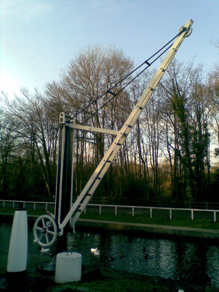 The cable run has to come from the drum up and over the pillar: 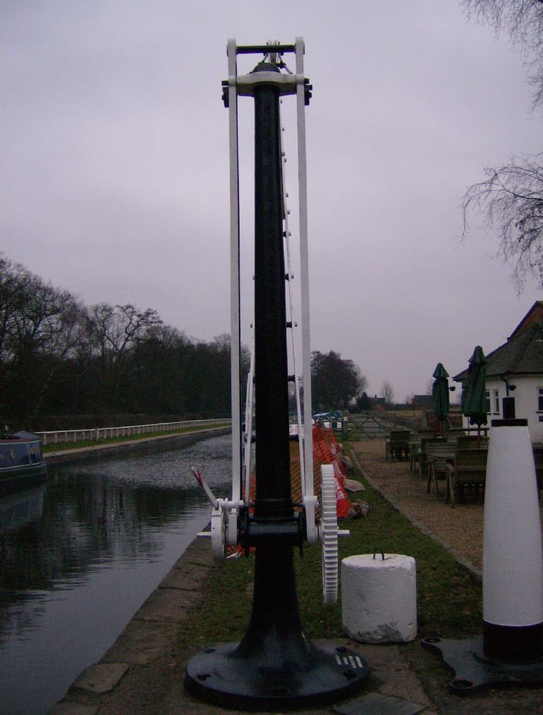 The cable drum is here (note the fixing loop and ratchet - the brake is fitted to a replacement for a broken lug on the ratchet dog, the brake should mount on two studs that would position it to work on the - missing- winding handle). 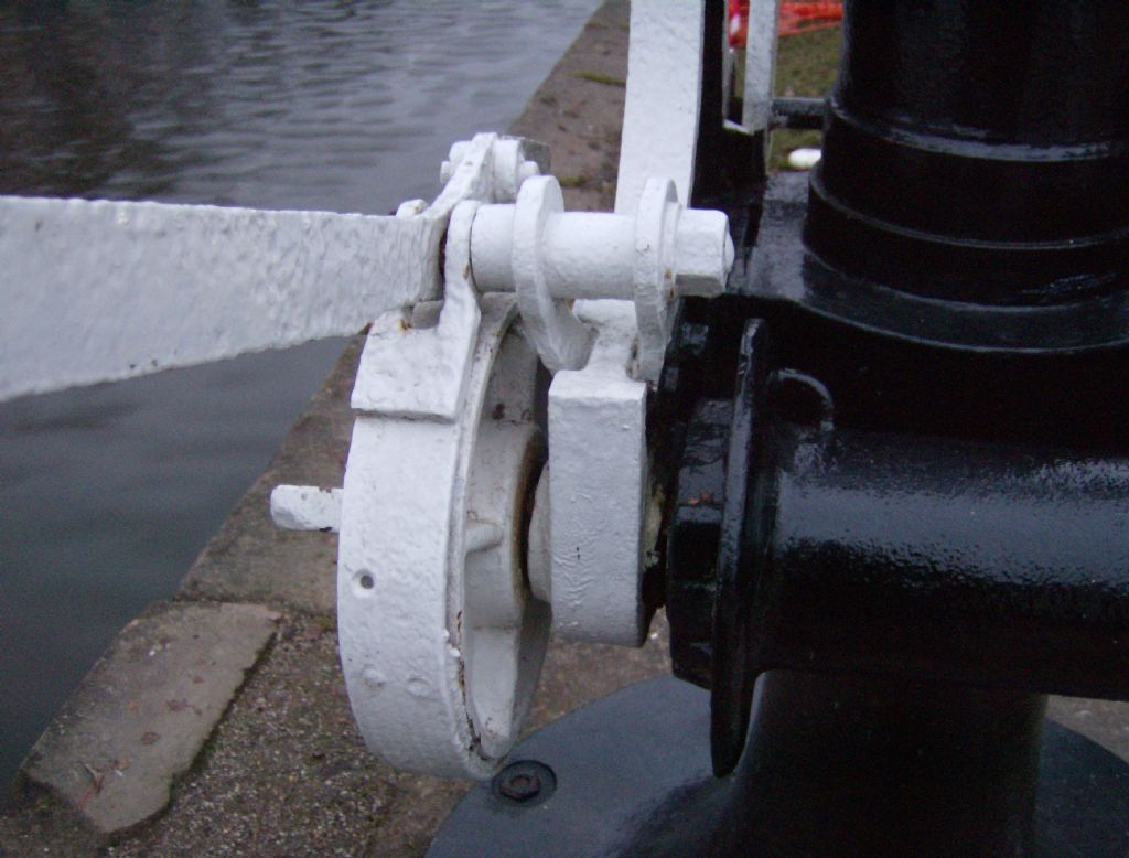 But this is the obstacle the cable has to get over - no room for a decent size pulley? 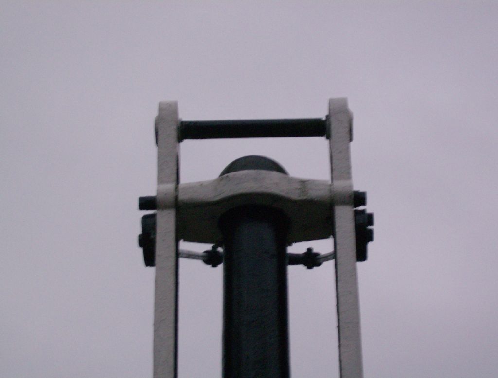 My thought - the bar across to the jib looks wrong, if the pivot was mounted the other way around it could provide a mounting point for a pulley support: 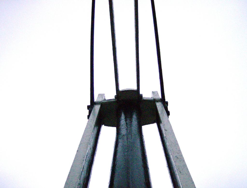 That's the evidence! An ideas? Thanks Neil |
| Weary | 08/02/2010 22:42:25 |
| 421 forum posts 1 photos | There was a complete eight part series on constructing a model hand-crane (and winch) that looks a little like your pics in Model Engineer in 1992/3 by Dave Lammas, starting in Volume 168 3rd Jan 1992, cover, and page 40.
An index search will give you the full list of issues and articles.
Dave Lammas' model did not swivel around a vertical column as your crane does, it rotated on a base-plate, so will not assist with the cable routing problem, but the works look similar - to my untutored eye.
It might be worth a browse?
The castings and drawings came from Woking Precision Models & plans were available from Argus Plans. |
| Martin W | 09/02/2010 00:26:38 |
| 940 forum posts 30 photos | Neil
Is it possible that a roller arrangement went on the axle at the top of the vertical column frames. Can't make out whether this would give enough clearance for rope/chain to clear the yoke holding the top pivot of the crane or not. I have had a quick browse for hand cranes, both canal and railway, and not found anything comparable yet.
Cheers
Martin W Edited By Martin W on 09/02/2010 00:39:16 |
| Ian S C | 09/02/2010 09:57:34 |
 7468 forum posts 230 photos | I imagine the pully at the top in the form of a roller with a flange at each end,ie cotton reel shape,it would perhaps help with laying the rope/cable evenly on the winch. Ian S C Edited By Ian S C on 09/02/2010 09:59:35 |
| Martin W | 09/02/2010 11:07:15 |
| 940 forum posts 30 photos | Ian S C
Much better explained but that was the sort of arrangement I was trying to suggest in my post. Its is the only thing that would appear to fit with the existing structure unless a second frame was mounted on the top axle which held a pulley but then why not just extend the side frames.
Cheers
Martin W |
| Stub Mandrel | 09/02/2010 21:52:05 |
4318 forum posts 291 photos 1 articles | I have got the late Dave Lammas' articles. He had some nice models that were off the beaten track - I think his last one was a spring hammer. The crane articles are useful, but as you say he doesn't have the routing problem and neither do LBSC and Tubal Cain's small steam cranes. It is hard to measure something that's on top of a 12 foot pole, but a 6" diameter roller would foul the top bearing, and a 4" diameter roller would not be large enough for the rope/cable to clear the bearing. You might just get away with a 5" roller, but that's a tight bend. I shall go away and consult my old Machinery's Handbook to see what would be a suitable rope and wire cable for 15 cwt SWL, and what radius it would bend to. |
| Stub Mandrel | 09/02/2010 22:06:06 |
4318 forum posts 291 photos 1 articles | Hm - much food for thought. 15cwt is about 3/4 of a ton, taking a safety factor of at least 10 and the lesser typer of steel in Machinery would indicate 1/2" wire rope (the groove in the pulley would take a larger rope, but the fixing loop on the drum suggests smaller. A calculation for pressure on drums or sheaves in Machinery is P=2*Tension/(sheave dia x rope dia) With a 12" sheave and a 1/2" rope and 15cwt tension I make the pressure 550lbs. The safe limits given for cast iron with different types of wire rope vary from 300 to 800lbs. With the winding drum itself being 8" diameter, this suggests a wire rope at least 3/4" diameter for safe running, and there's no way you could get away with a small roller at the top if it was cast iron or ordinary steel. For manilla rope you would need 1" dia for a 3/4 ton SWL, perhaps that's the answer, but a tight fit in the loop on the winding drum. I'm leaning towards adding a second 12" pulley on some sort of added frame. Neil |
| Martin W | 10/02/2010 01:20:35 |
| 940 forum posts 30 photos | Neil
I have had a look at the photo of the winding gear and, I expect you have tried this avenue, it looks as if the crane was made in Earlestown Lancashire. The manufacturer's name I haven't been able to decipher but it looks almost like Jeslee. Have looked at some historical maps for Earlestown but couldn't see them mentioned, dead end
 . There was of course the railway works there which may have produced cranes etc. but no records. . There was of course the railway works there which may have produced cranes etc. but no records.Cheers
Martin W |
| Ian S C | 10/02/2010 08:50:18 |
7468 forum posts 230 photos | I'v been looking at the net,and on a number of cranes of similar size and vintage chain is used rather than rope or cable.You proberbly will have see or know of the Ellesmere Boat Museum in Cheshire.They have a hand crane,and the chain is supported by rollers up the jib support similar to what I suggested.(type in Ellesmere Boat Museum, you'll find photos,worth a look anyway). This looks like an interesting project, I get into similar sorts of jobs here in NZ,ie a vintage water turbine. Ian S C |
| Stub Mandrel | 10/02/2010 21:55:46 |
4318 forum posts 291 photos 1 articles | Hi Martin There is a plate at the base of the crane giving a brief history. I thought the name was J Slee, but the plate says it is J S Lee. I googled for ("J S Lee" earlestown Lancashire), and it came up with 2 hits - a list of Irishmen and a crane at Fradley junction  Hi Ian, I won't lose anything by trying your suggestion - if there isn't room, I just add a pulley instead.I will try and take l look at the elsemere crane. I'd be interested to see some pics of the water turbine or other Kiwi engineering. Thanks both, Neil |
| Martin W | 11/02/2010 14:17:38 |
| 940 forum posts 30 photos | Neil
You are probably aware of the fact that this crane was rescued from Horninglow Basin, Burton on Trent and re-erected at Fradley in 1977. I have a quick look to see if I could find any historical photos of Horninglow but to no avail.
Cheers
Martin |
| Martin W | 11/02/2010 18:06:09 |
| 940 forum posts 30 photos | Neil
I found this picture of a crane, not the same as yours, but it has a chain to the hook and like yours the stay from the jib to the column has several cross members which appear to be the chain support.
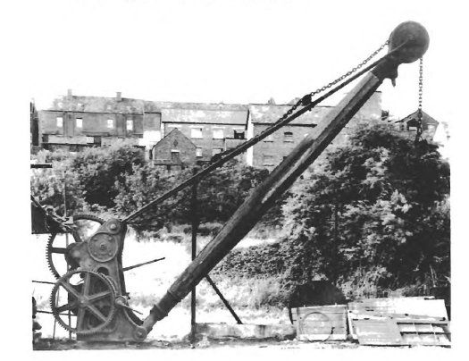 Cheers Martin |
| Stub Mandrel | 11/02/2010 21:23:50 |
4318 forum posts 291 photos 1 articles | Martin, that's an amazing photo, the wooden beam is extraordinary! I'll have to add that pic to my 'future models' file It's rather bigger than mine - you can see it has two sets of gears instead of one and the handles are quite low down by comparison (or the crane is bigger and they are the same height, if you get what I mean). I'd guess the cable drum at right is about 4' diameter. I see what you and Ian mean about rollers. Regards Neil |
| Martin W | 12/02/2010 00:11:47 |
| 940 forum posts 30 photos | Neil
This might be of interest as it is an extension to the photo. It gives a description of the crane and a schematic drawing which is scaled. The web address is http://www.gsia.org.uk/reprints/1995/gi199521.pdf
Another project maybe
 !!!! !!!!Regards
Martin |
| Ian S C | 13/02/2010 08:52:23 |
7468 forum posts 230 photos | I found anothe one on an Austrailian site sunshinecoastdaily,blogspot.com It is a similar one to yours,the winch in the same place. At the top of the pole is another winch with the chain on it, this winch has a large ?flywheel ?pully proberbly 4ft or so dia,I can't see how they are connected. I tried to put some photos of our old turbine on but couldn't get them to go,I'll keep on at it though. Ian S C |
| Martin W | 13/02/2010 11:16:15 |
| 940 forum posts 30 photos | Hi
Another good picture of this heavier crane can be found at http://www.disused-stations.org.uk/ under the closed station of Ruthin. Its a nice detailed colour image of the other, left hand, side.
Cheers
Martin |
| Stub Mandrel | 13/02/2010 22:58:09 |
4318 forum posts 291 photos 1 articles | The plot thickens! I was wondering about J S LEE - I it doesn't look right on the base so I took a close look at this: 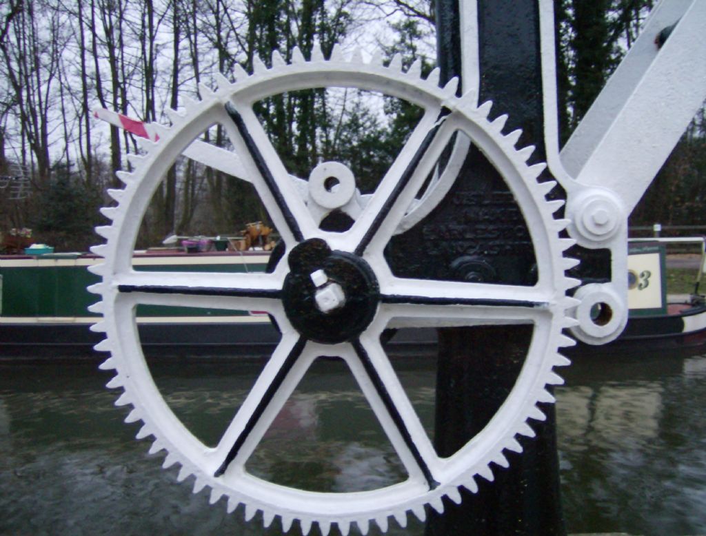 Get in close and it says "J.SLEE" google Slee Earlestown and you turn up a plenty of links to a 19C manufacturer. So the info plate is wrong! Thanks for your description Ian, I think a second decent sized pulley belongs at the top of the pillar now. I have been reading 'Machinery's Handbook' and a rope strong enough for 15cwt would need a big pulley too. My money os on 5/8" or 1/2" rope and two 12" pulleys now. Thanks both, neil |
| Ian S C | 15/02/2010 12:11:06 |
7468 forum posts 230 photos | Neil, go to google images,put in Blackness Castle Crane, and you will see one similar to yours,with a pully at the top of the pole,this could be 1 1/2 to 2ft dia. Ian S C |
Please login to post a reply.
Magazine Locator
Want the latest issue of Model Engineer or Model Engineers' Workshop? Use our magazine locator links to find your nearest stockist!
Sign up to our Newsletter
Sign up to our newsletter and get a free digital issue.
You can unsubscribe at anytime. View our privacy policy at www.mortons.co.uk/privacy
Latest Forum Posts
- *Oct 2023: FORUM MIGRATION TIMELINE*
05/10/2023 07:57:11 - Making ER11 collet chuck
05/10/2023 07:56:24 - What did you do today? 2023
05/10/2023 07:25:01 - Orrery
05/10/2023 06:00:41 - Wera hand-tools
05/10/2023 05:47:07 - New member
05/10/2023 04:40:11 - Problems with external pot on at1 vfd
05/10/2023 00:06:32 - Drain plug
04/10/2023 23:36:17 - digi phase converter for 10 machines.....
04/10/2023 23:13:48 - Winter Storage Of Locomotives
04/10/2023 21:02:11 - More Latest Posts...
- View All Topics
Support Our Partners


Shopping Partners
Subscription Offer

Latest "For Sale" Ads
- Reeves** - Rebuilt Royal Scot by Martin Evans
by John Broughton
£300.00 - BRITANNIA 5" GAUGE James Perrier
by Jon Seabright 1
£2,500.00 - Drill Grinder - for restoration
by Nigel Graham 2
£0.00 - WARCO WM18 MILLING MACHINE
by Alex Chudley
£1,200.00 - MYFORD SUPER 7 LATHE
by Alex Chudley
£2,000.00 - More "For Sale" Ads...
Latest "Wanted" Ads
- D1-3 backplate
by Michael Horley
Price Not Specified - fixed steady for a Colchester bantam mark1 800
by George Jervis
Price Not Specified - lbsc pansy
by JACK SIDEBOTHAM
Price Not Specified - Pratt Burnerd multifit chuck key.
by Tim Riome
Price Not Specified - BANDSAW BLADE WELDER
by HUGH
Price Not Specified - More "Wanted" Ads...
Get In Touch!
Do you want to contact the Model Engineer and Model Engineers' Workshop team?
You can contact us by phone, mail or email about the magazines including becoming a contributor, submitting reader's letters or making queries about articles. You can also get in touch about this website, advertising or other general issues.
Click THIS LINK for full contact details.
For subscription issues please see THIS LINK.
Digital Back Issues


Donate

 Register
 Log-in
Model Engineer Magazine
- Percival Marshall
- M.E. History
- LittleLEC
- M.E. Clock

ME Workshop
- An Adcock
- & Shipley
- Horizontal
- Mill

Subscribe Now
- Great savings
- Delivered to your door

Pre-order your copy!
- Delivered to your doorstep!
- Free UK delivery!
All Forum Topics > Miscellaneous models > Hand Crane