Forum sponsored by:

Lathe toolpost stud thread repair ideas
| Carl Farrington | 10/09/2023 18:18:11 |
| 47 forum posts | Hi all The toolpost-stud threads on my Churchill Cub lathe are damaged. It has previously had a hole drilled for a grub screw between the threads, which might make make a helicoil thread-repair questionable. It's also not possible to fix from underneath as there is no clearance. My father in law has suggested we machine and freeze-fit then pin a 'plug' which we drill and tap. Also we were thinking of just tapping it for a bolt rather than doing a stud and nut. I was wondering what the reasons were that they always use studs and not bolts. I'm thinking it might be to preserve the threads in the casting! I've made a short youtube video and was wondering if anyone could offer up any ideas? - https://www.youtube.com/watch?v=FX7ox0a3IQM
thanks very much, Carl Edited By Carl Farrington on 10/09/2023 18:18:56 |
| Nick Wheeler | 10/09/2023 18:30:27 |
| 1227 forum posts 101 photos | It's to make the thread that wears out on an easily replaceable, consumable part. Wouldn't you rather buy a new stud than make the repair you now have to do? |
| Carl Farrington | 10/09/2023 18:33:43 |
| 47 forum posts | Posted by Nick Wheeler on 10/09/2023 18:30:27:
It's to make the thread that wears out on an easily replaceable, consumable part. Wouldn't you rather buy a new stud than make the repair you now have to do? Yep.. absolutely. I thought it might be that. Thanks for confirming. |
| Martin Connelly | 10/09/2023 18:51:39 |
 2549 forum posts 235 photos | Grub screw is probably anti-rotation. I think the side pocket may have been for an indexing system for a tool post that located in the circular pocket. I think I would see if I could get an M20 x 1.5 or M20 x 1.75 tap. Make a new tool post stud to suit this M20 thread, and tap the slide to M20. If the circular pocket is no longer in use make a collar to secure the stud in place and put a couple of screws through the slide from below into the collar in the pocket. Martin C |
| Carl Farrington | 10/09/2023 19:38:00 |
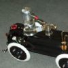
| 47 forum posts | Thanks Martin. I just checked and M20 is the ideal fit for the Multifix holder (if the bushing is removed). I did just have another, almost obvious idea though. I could make a 'plug' that isn't a press fit, and use 4x M6 or M5 cap-head bolts to fix it in place. It seems like there's ample room. This would be replaceable then if need be
In the picture below I have some M5 bolts (what I had to hand) sat on their heads for ease of photographing, but I would fit them from above, counterboring in the plug. I like your idea of a collar to come in from the side too.. thanks!
Edited By Carl Farrington on 10/09/2023 19:38:46 |
| magpie | 10/09/2023 19:39:06 |
 508 forum posts 98 photos | I had to stop watching that at about a half minute because i started to feel dizzy at the way the camera was moving. |
| Carl Farrington | 10/09/2023 19:44:29 |
| 47 forum posts | Posted by magpie on 10/09/2023 19:39:06:
I had to stop watching that at about a half minute because i started to feel dizzy at the way the camera was moving. Yep, sorry. It's pretty hard to film holding a mobile phone in your hand. Much easier with a GoPro. |
| not done it yet | 10/09/2023 20:48:44 |
| 7517 forum posts 20 photos | Can you shim under the tool-post until it lines up exactly with the threads for the grub screw when fitted tightly in the threads? Then fix the grub screw in position to retain the post?
|
| Clive Foster | 10/09/2023 22:12:43 |
| 3630 forum posts 128 photos | Carl The Churchill Cub Mk3 had 3 alternative tool posts. Flt top and stud for a simple clamp or block type, T-slotted for American style lantern post and UK style ratcheting 4 way. See **LINK** , http://www.lathes.co.uk/churchill-cub/ for pictures. I imagine the deep hole on yours contains the ratcheting and location gubbins. In your third post you imply that you propose to use a Multifix QC system. This requires a flat mounting surface on top of the slide so sensible option is to fill the aperture with a solid block that will sit flush with the flat portion of the slide top and fit the stud to that. Which I presume is what you propose in your last post. 4 M5 cap head screws coming up from the bottom will do fine. That said the base appears fairly thin there so maybe counter sunk heads would live more metal to take the loads. I'd glue'n screw with high strength loctite on the base assuming itself reasonably flat. If it's uneven something with a bit more build such as epoxy or JB weld might be better. Its never coming out again is it. When you fit your stud do receive the first thread to prevent the thread being pulled upwards a touch and making the surface the tool post sits on non-flat. If thats surface isn't decently flat the post will try to rotate. best practice is collar on the stud, like your original, sitting into a recess. A thin aluminium alloy sheet between the toolpost and support surface significantly improves the grip against twist so only m moderate hold down nut torque will suffice. Gorriloid larruping up a tool post nut in a doomed attempt to stop it twisting as left many a topslide top seriously distorted. Clive |
| Brian Wood | 12/09/2023 12:45:35 |
| 2742 forum posts 39 photos | Hello Carl, Clive's post above seems to be the most sensible option and I certainly endorse his recommendation for holding the filler block with countersunk screws from below, as well as relieving any threading to the upper flat surface to prevent swelling to interfere with an otherwise flat surface Incidentally, you have the Cub Mk3A which came as standard with the full Norton gearbox. I don't know the age of your lathe but if the Serial number finishes in 49 or higher it probably has the uprated spindle clutch. Mine is a salvage job from a Steptoe like scrap yard; it is the Cub Mk3 with the simpler three selector semi-Norton box, making the lathe effectively a change wheel machine with 3 variants on each pitch selection. It was made in 1947 and comes with the Tee slotted insert across the top-slide to carry the 3/4 inch diameter tool post and indexing 4 way tool holder. The insert, tool post and 4 way holder are all hardened. I would like to find another full gearbox as I am convinced I could do a straight swap with mine, but like hen's teeth they are rare beasts. I hope you can put yours right, it is certainly not so as it stands. Regards Brian |
| Carl Farrington | 12/09/2023 12:59:46 |
| 47 forum posts | Thanks guys.
I understand, however I was planning to fit the screws (cap head hex bolts) from above. Counterboring the filler block. There is not much (probably not enough) meat in the base of the casting to counterbore to any depth really. Also, keep in mind that the void that you can see there is a fair bit smaller in diameter than the multifix holder's base. The stud sits in a void, yet the multifix clamps down just fine on what material is left of the casting outside this void. Does that make any sense? Edited By Carl Farrington on 12/09/2023 13:06:12 |
| Brian Wood | 12/09/2023 14:24:59 |
| 2742 forum posts 39 photos | Carl, All we can do is offer advice on what we see. You are at the sharp end and ultimately the way ahead will be what you feel comfortable with. Either way, good luck Brian |


Please login to post a reply.
Magazine Locator
Want the latest issue of Model Engineer or Model Engineers' Workshop? Use our magazine locator links to find your nearest stockist!
Sign up to our Newsletter
Sign up to our newsletter and get a free digital issue.
You can unsubscribe at anytime. View our privacy policy at www.mortons.co.uk/privacy
Latest Forum Posts
- hemingway ball turner
04/07/2025 14:40:26 - *Oct 2023: FORUM MIGRATION TIMELINE*
05/10/2023 07:57:11 - Making ER11 collet chuck
05/10/2023 07:56:24 - What did you do today? 2023
05/10/2023 07:25:01 - Orrery
05/10/2023 06:00:41 - Wera hand-tools
05/10/2023 05:47:07 - New member
05/10/2023 04:40:11 - Problems with external pot on at1 vfd
05/10/2023 00:06:32 - Drain plug
04/10/2023 23:36:17 - digi phase converter for 10 machines.....
04/10/2023 23:13:48 - More Latest Posts...
- View All Topics
Support Our Partners


Shopping Partners
Subscription Offer

Latest "For Sale" Ads
- Reeves** - Rebuilt Royal Scot by Martin Evans
by John Broughton
£300.00 - BRITANNIA 5" GAUGE James Perrier
by Jon Seabright 1
£2,500.00 - Drill Grinder - for restoration
by Nigel Graham 2
£0.00 - WARCO WM18 MILLING MACHINE
by Alex Chudley
£1,200.00 - MYFORD SUPER 7 LATHE
by Alex Chudley
£2,000.00 - More "For Sale" Ads...
Latest "Wanted" Ads
- D1-3 backplate
by Michael Horley
Price Not Specified - fixed steady for a Colchester bantam mark1 800
by George Jervis
Price Not Specified - lbsc pansy
by JACK SIDEBOTHAM
Price Not Specified - Pratt Burnerd multifit chuck key.
by Tim Riome
Price Not Specified - BANDSAW BLADE WELDER
by HUGH
Price Not Specified - More "Wanted" Ads...
Get In Touch!
Do you want to contact the Model Engineer and Model Engineers' Workshop team?
You can contact us by phone, mail or email about the magazines including becoming a contributor, submitting reader's letters or making queries about articles. You can also get in touch about this website, advertising or other general issues.
Click THIS LINK for full contact details.
For subscription issues please see THIS LINK.
Digital Back Issues


Donate

 Register
 Log-in
Model Engineer Magazine
- Percival Marshall
- M.E. History
- LittleLEC
- M.E. Clock

ME Workshop
- An Adcock
- & Shipley
- Horizontal
- Mill

Subscribe Now
- Great savings
- Delivered to your door

Pre-order your copy!
- Delivered to your doorstep!
- Free UK delivery!
All Forum Topics > General Questions > Lathe toolpost stud thread repair ideas