Forum sponsored by:

Amateurish Engine
| JasonB | 29/05/2023 16:47:03 |
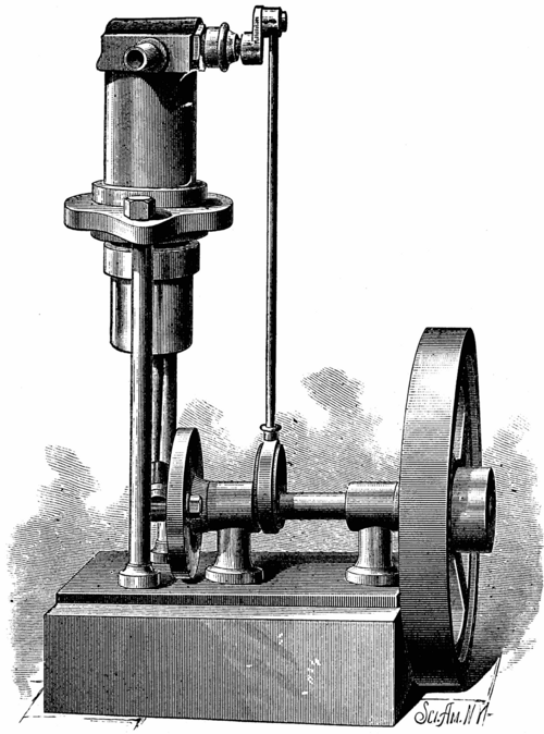
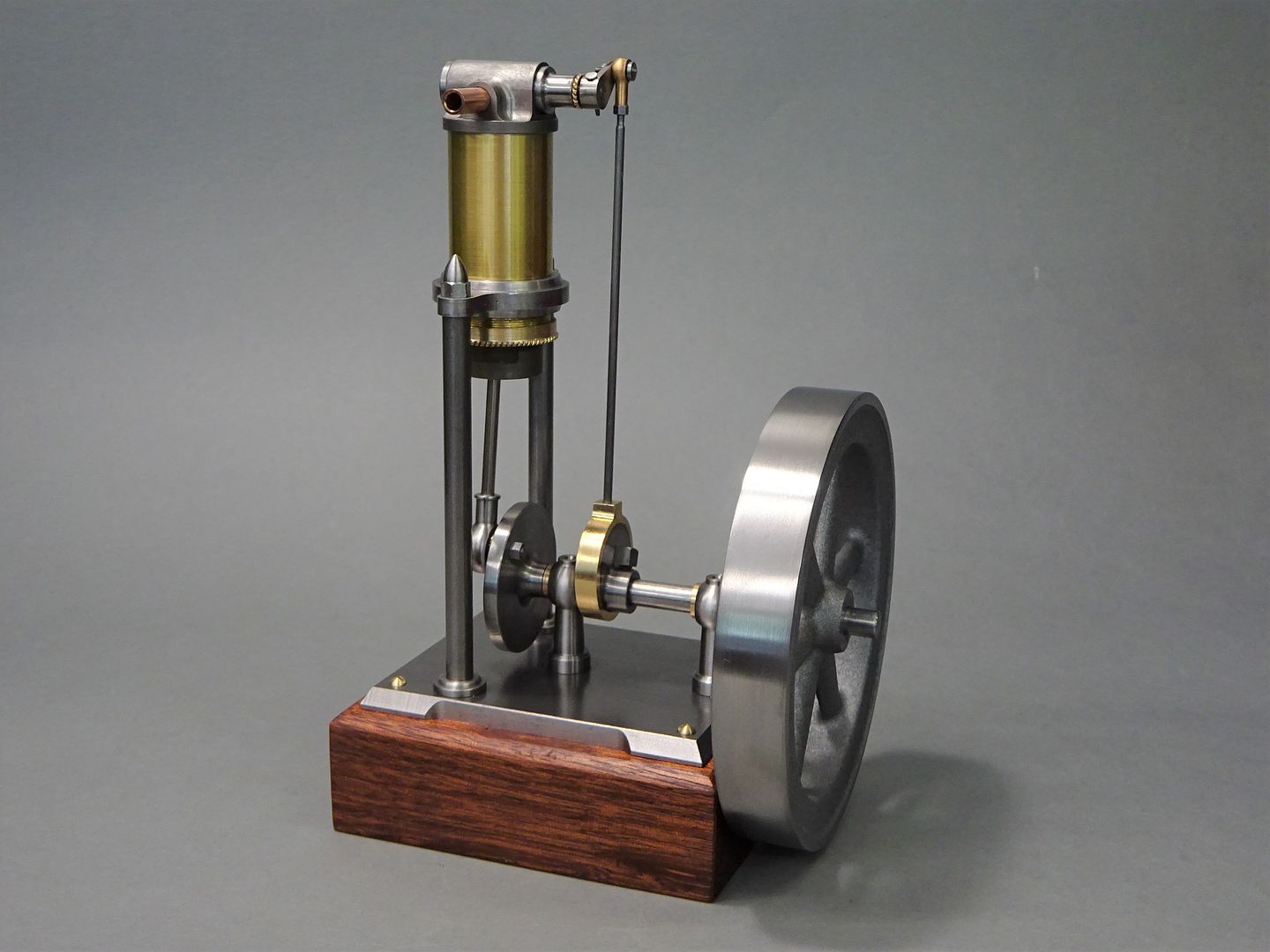
 25215 forum posts 3105 photos 1 articles | I think I first saw the image below of this engine when it came up on Pintrest and it caught my eye. A bit more digging about with Google showed that it originated from the 1905 edition of "Scientific American" and was listed under Amateur Mechanics as a "Simple Single-Acting Steam Engine" Edited By JasonB on 29/05/2023 17:00:35 |
| Nigel Graham 2 | 29/05/2023 22:57:16 |
| 3293 forum posts 112 photos | Interesting engine! I wonder if it was based on a full-size one by some manufacturer perhaps no longer trading even before Scientific American published the model design. |
| JasonB | 30/05/2023 06:58:42 |
25215 forum posts 3105 photos 1 articles | It was not published as a "Model" they say it would be capable of powering the treadle lathe it was built on or 2-3 sewing machines. Although the terms are more often used for IC engines I would class it as a "small power" or Fractional Horsepower" workshop engine. |
| not done it yet | 30/05/2023 07:17:01 |
| 7517 forum posts 20 photos | JB, Did you reduce other dimensions - other than the bore? If you halved the bore it will be only one quarter (not half) of the capacity, surely? |
| JasonB | 30/05/2023 07:39:29 |
25215 forum posts 3105 photos 1 articles | Posted by not done it yet on 30/05/2023 07:17:01:
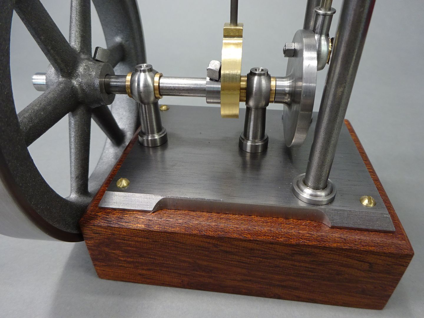
JB, Did you reduce other dimensions - other than the bore? If you halved the bore it will be only one quarter (not half) of the capacity, surely? Yes all reduced by approx 50% so everything is half size, 25mm stroke from original 2" and 99mm flywheel dia from original 8" dia (100mm stock hence 99mm finish) Capacity is actually 1/8th of the original 0.5 x 0.5 x 0.5 Edited By JasonB on 30/05/2023 07:40:14 |
| Phil Whitley | 30/05/2023 10:03:57 |
 1533 forum posts 147 photos | https://www.youtube.com/watch?v=u_F5OGjLpOQ This ICE design seems to use the same induction/exhause valve system. Phil |
| JasonB | 30/05/2023 11:27:56 |
25215 forum posts 3105 photos 1 articles | That looks more like what you tend to find on a lot of front induction model aero engines where the incoming air/fuel mix is drawn in via a hollow crankshaft.
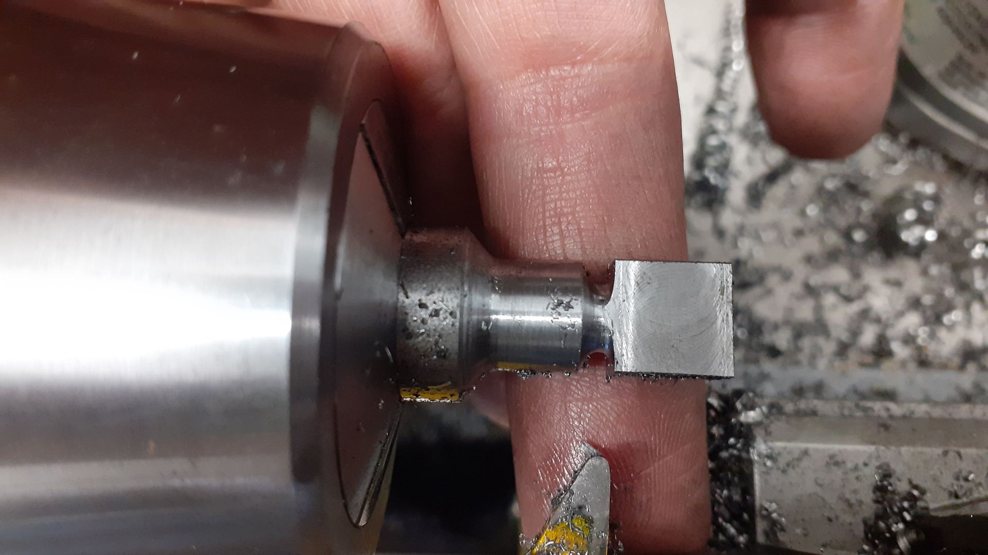
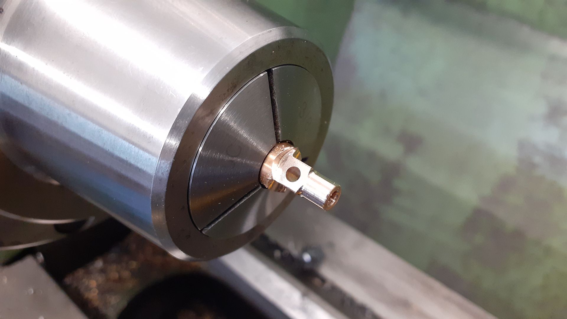
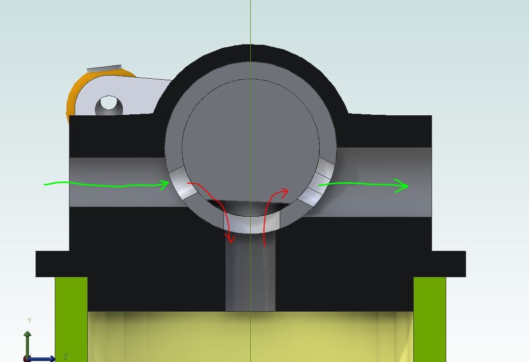
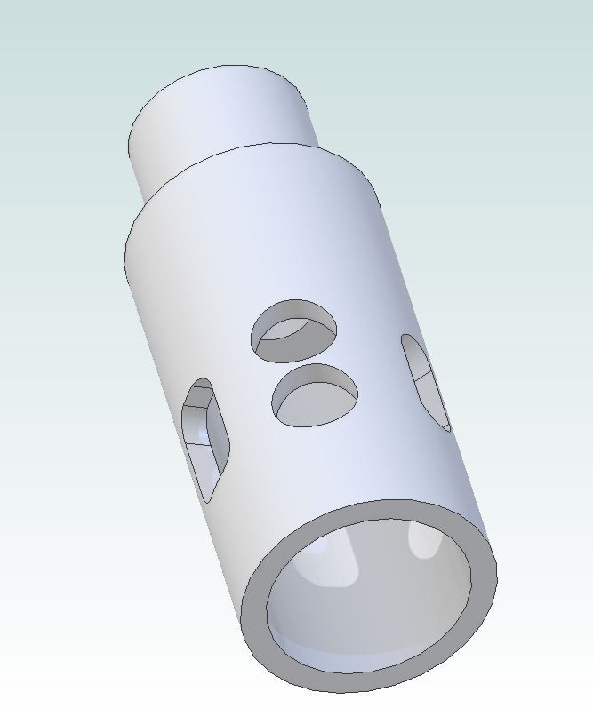
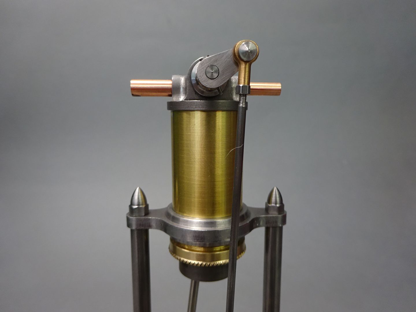
The rocking valve is really nothing more than a diverter valve or can be thought of like a common steam engine slide valve except the port face is curved not flat. This is the one for this single acting engine as the valve spindle with a simple flat machined on it rocks it opens the inlet and then the exhaust and so on
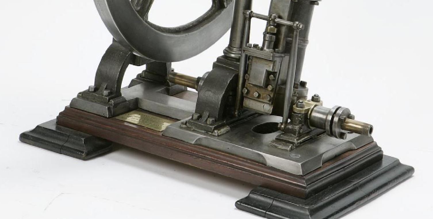
Things get a bit more complex on a double acting engine, this is the one from my Filer and Stowell where the incoming air/steam passes around the valve much like filling a traditional valve chest and then as the valve rotates one side is open to the incoming while at the same time the cavity in the valve links the other end to the central exhaust
|
| Hopper | 30/05/2023 11:42:34 |
 7881 forum posts 397 photos | A rotary sleeve valve like that was tried on various motorcycles back in the 1920s but they could never maintain a good seal once the rotary sleeve and its housing in the cylinder head wore a bit. And being subject to hot corrosive exhaust gasses, wear was rapid. The rocking valve on the old steam engine in the OP is more reminiscent of a Corliss type valve gear. Pretty neat to watch in action. |
| JasonB | 30/05/2023 11:54:59 |
25215 forum posts 3105 photos 1 articles | That's it Hopper just like a corliss valve except it has two ports to open/close rather than one. The makers of that Filer and Stowell were better known for their corliss engines but did the less complex/expensive rocking valve ones where economy was not much of an issue hence they were often found in saw mills that had a good supply of waste wood to fire the boilers |
| JasonB | 30/05/2023 18:30:58 |
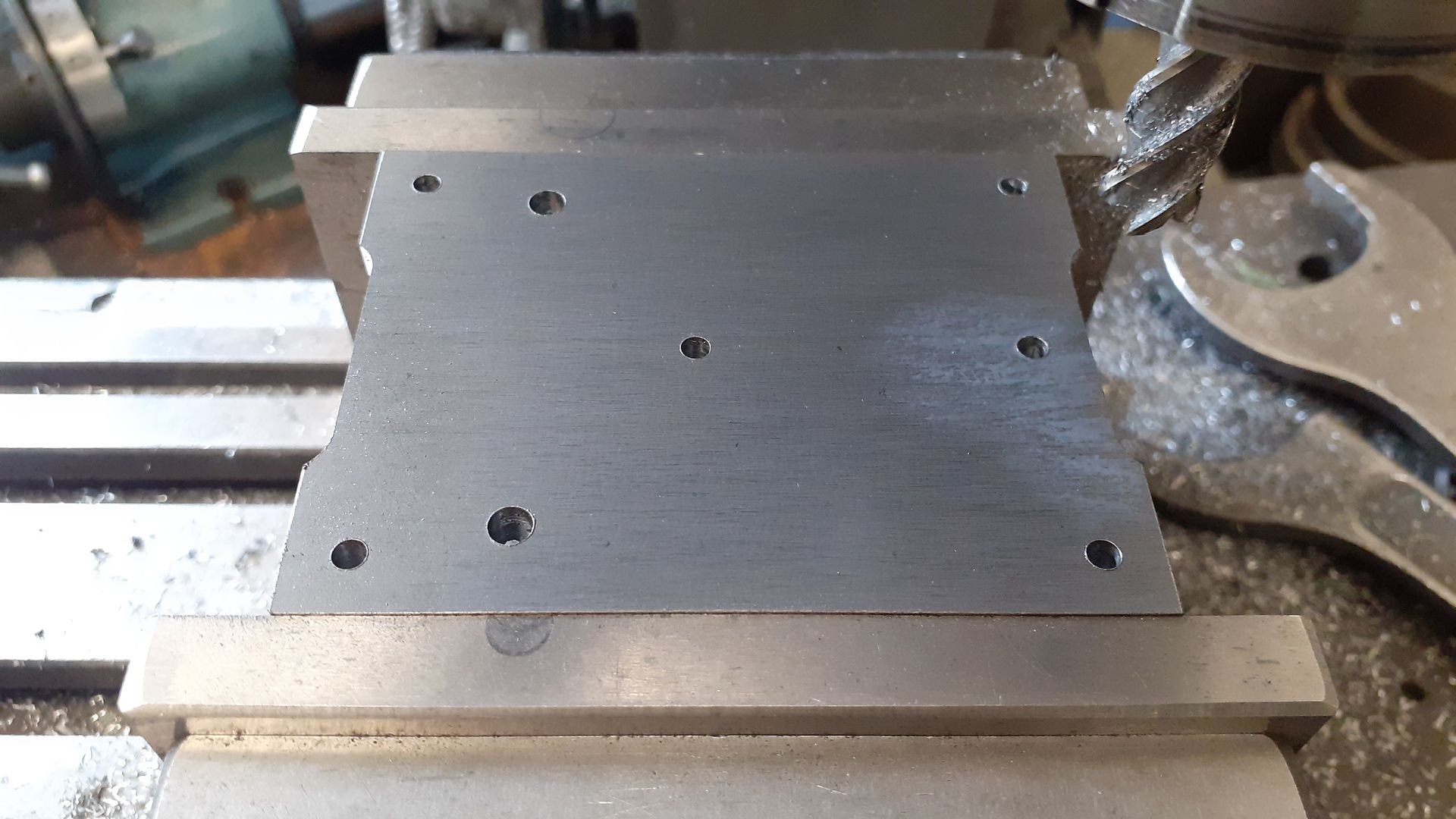
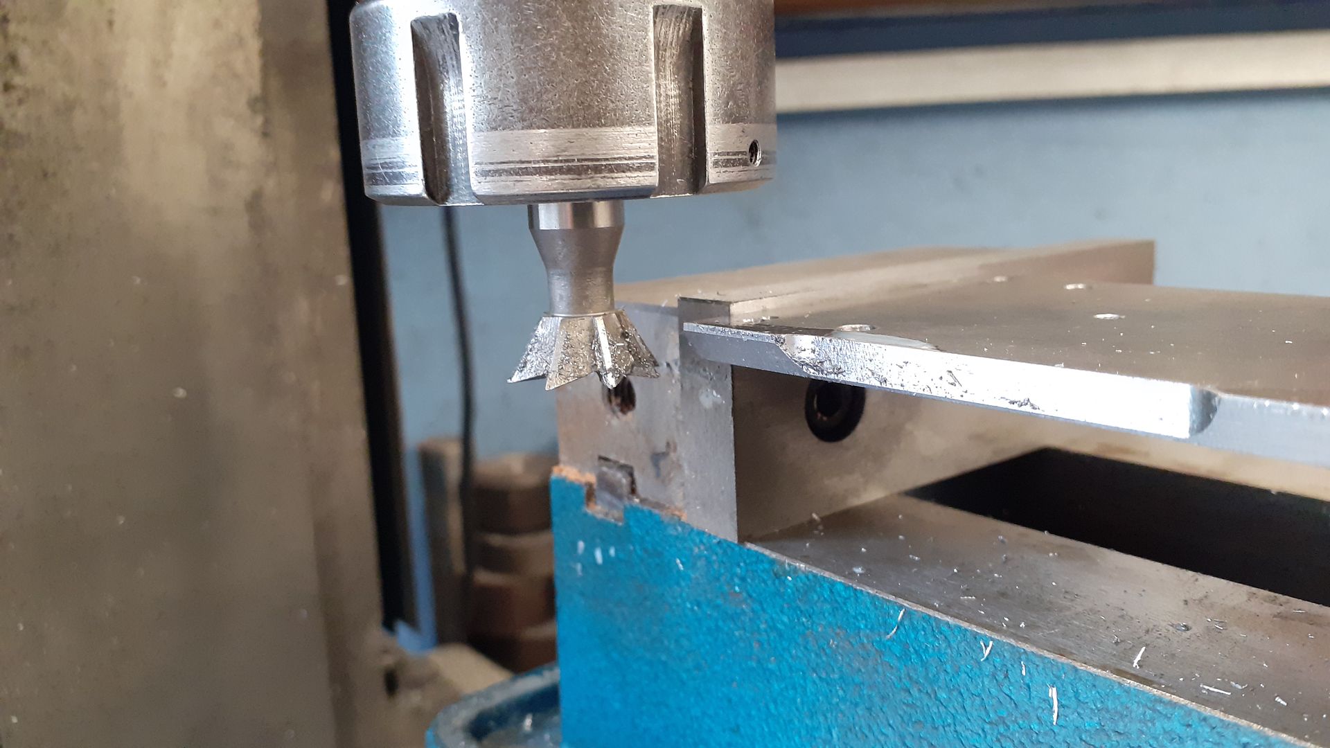
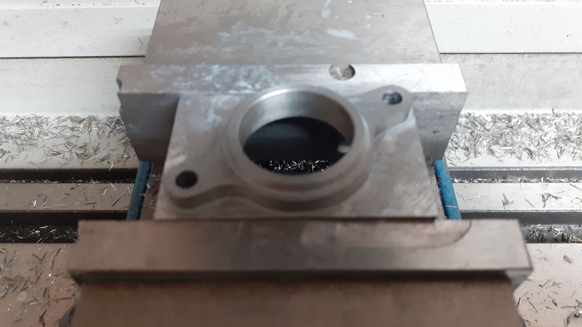
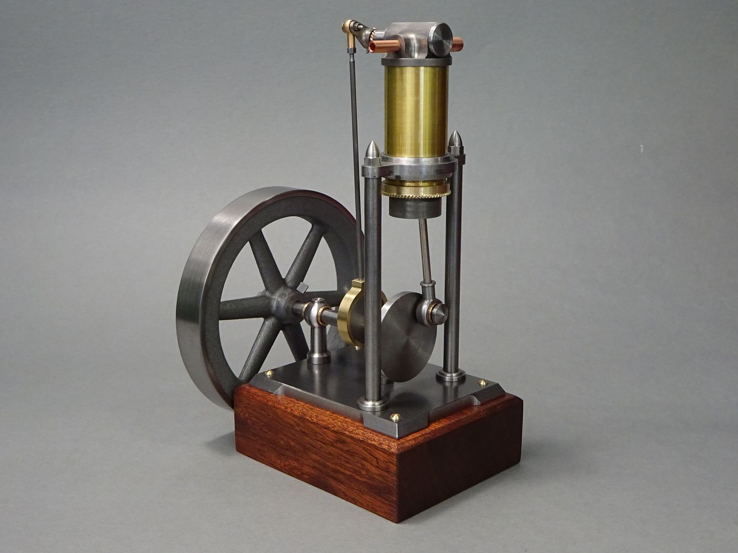
25215 forum posts 3105 photos 1 articles | As I mentioned in the opening post I wanted to add a bit more detail and ornamentation and the rather plain flat plate of the original engines base was the first candidate for that. I have had a couple of images of this engine in my "future projects" file and likes the edge detail it featured. Edited By JasonB on 30/05/2023 18:33:23 |
| Tim Stevens | 31/05/2023 18:37:54 |
 1779 forum posts 1 photos | The date of this engine puts it bang in the middle of a period of history when there was a huge demand from all sorts of people for a small source of power. Sewing machines are mentioned, but there were also printers, dairies, bookbinders, etc, all needing power but not all the time (which is what steam was good for) The electric motor was going to solve their problems, but they had to wait for national distribution systems. Simple engines like this could help, but tended to involve fire risks, so were difficult to insure. Cheers, Tim |
| JasonB | 01/06/2023 20:40:29 |
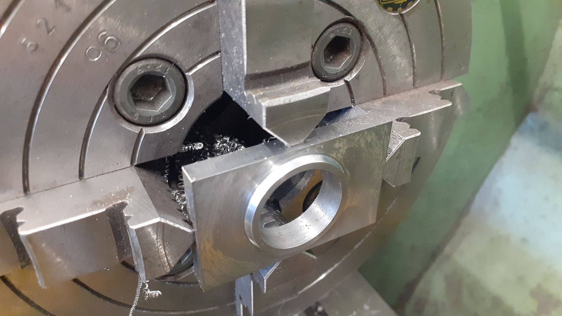
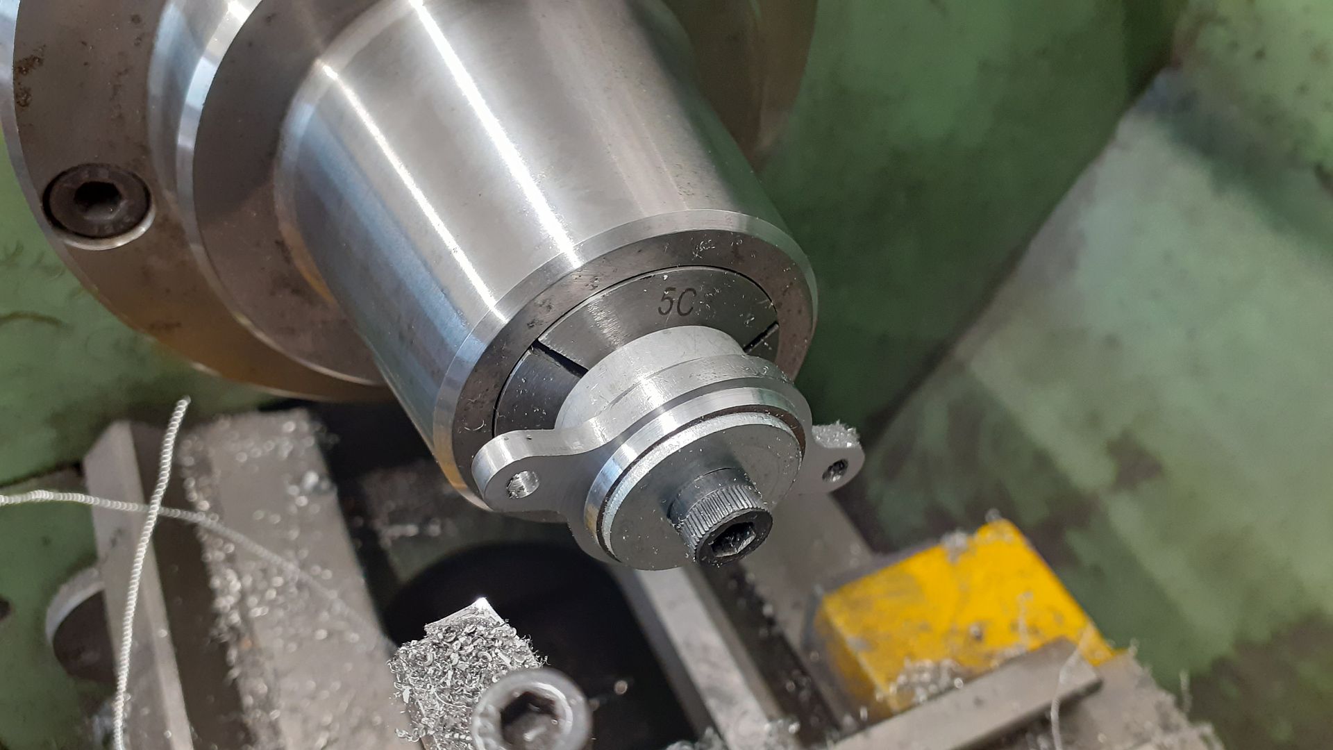
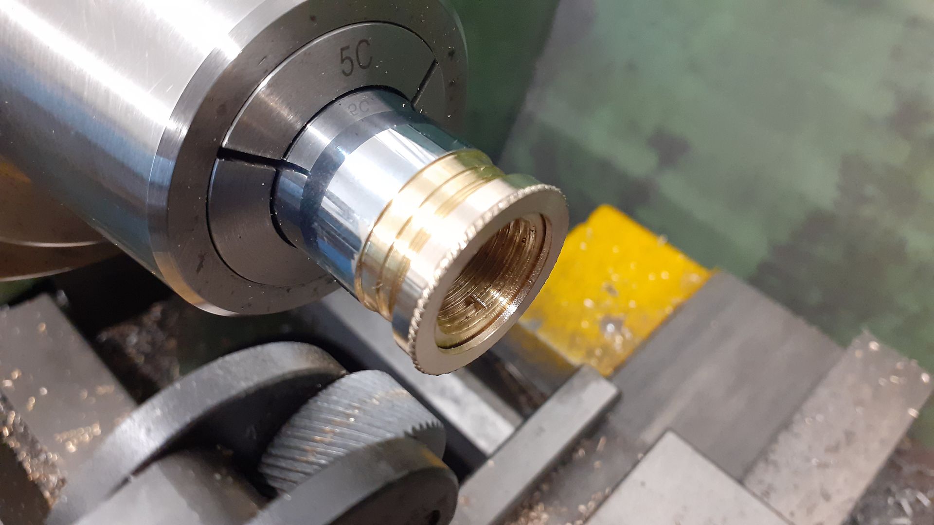
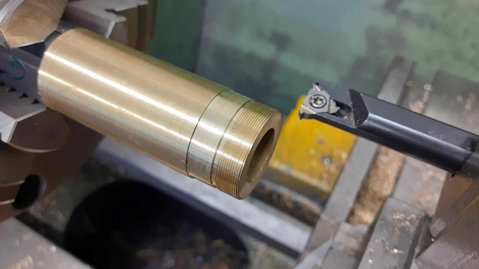
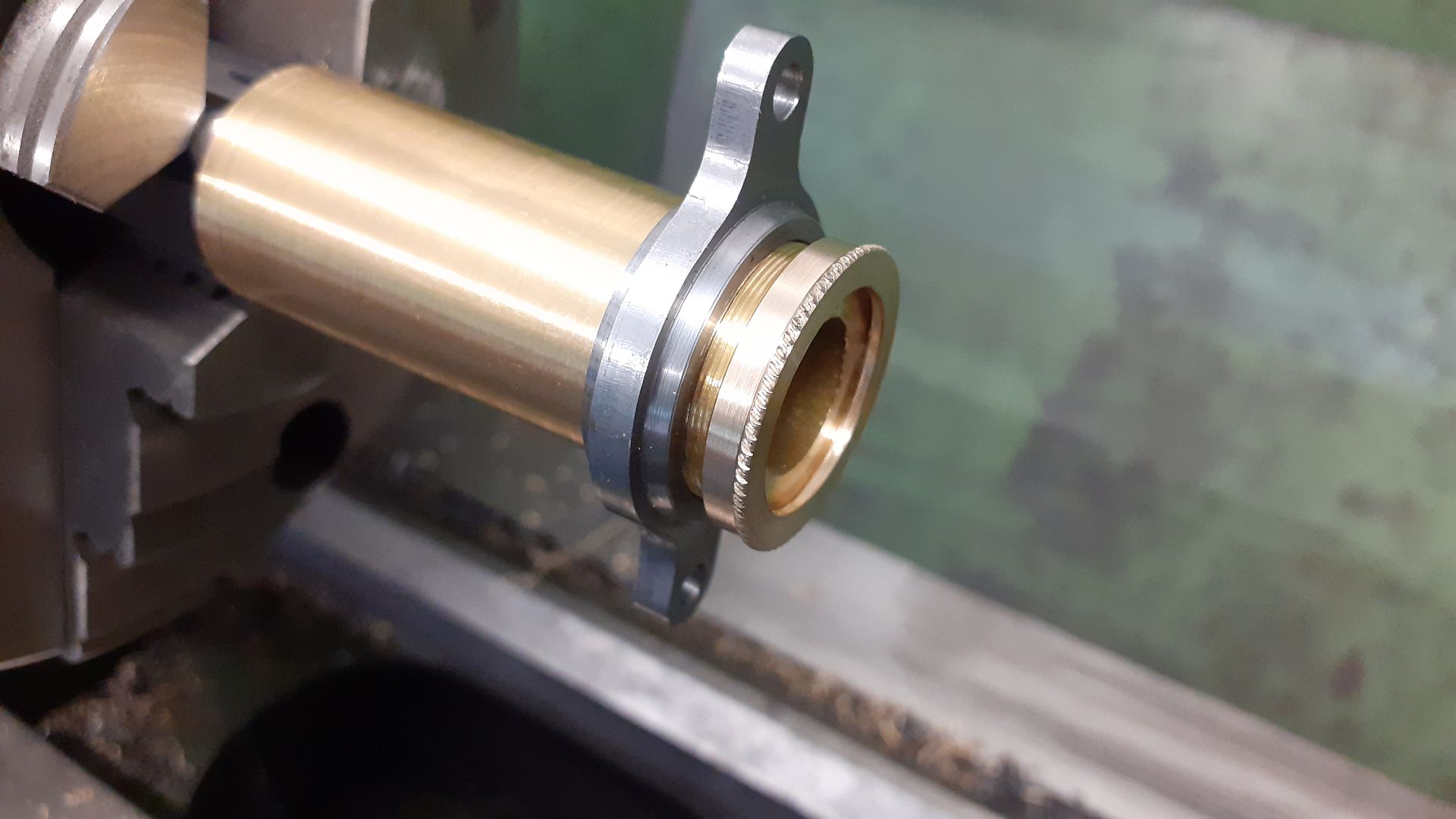
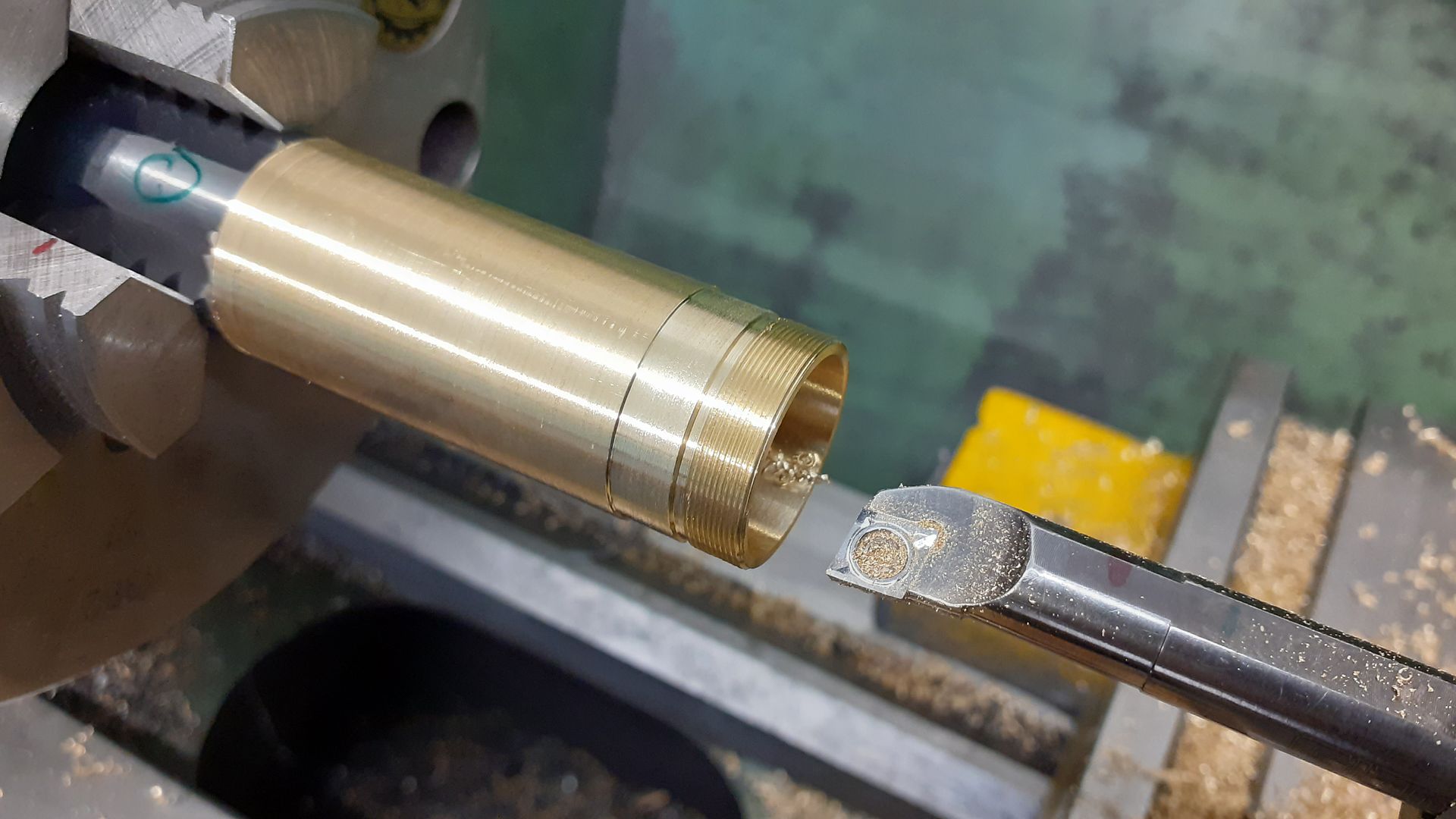
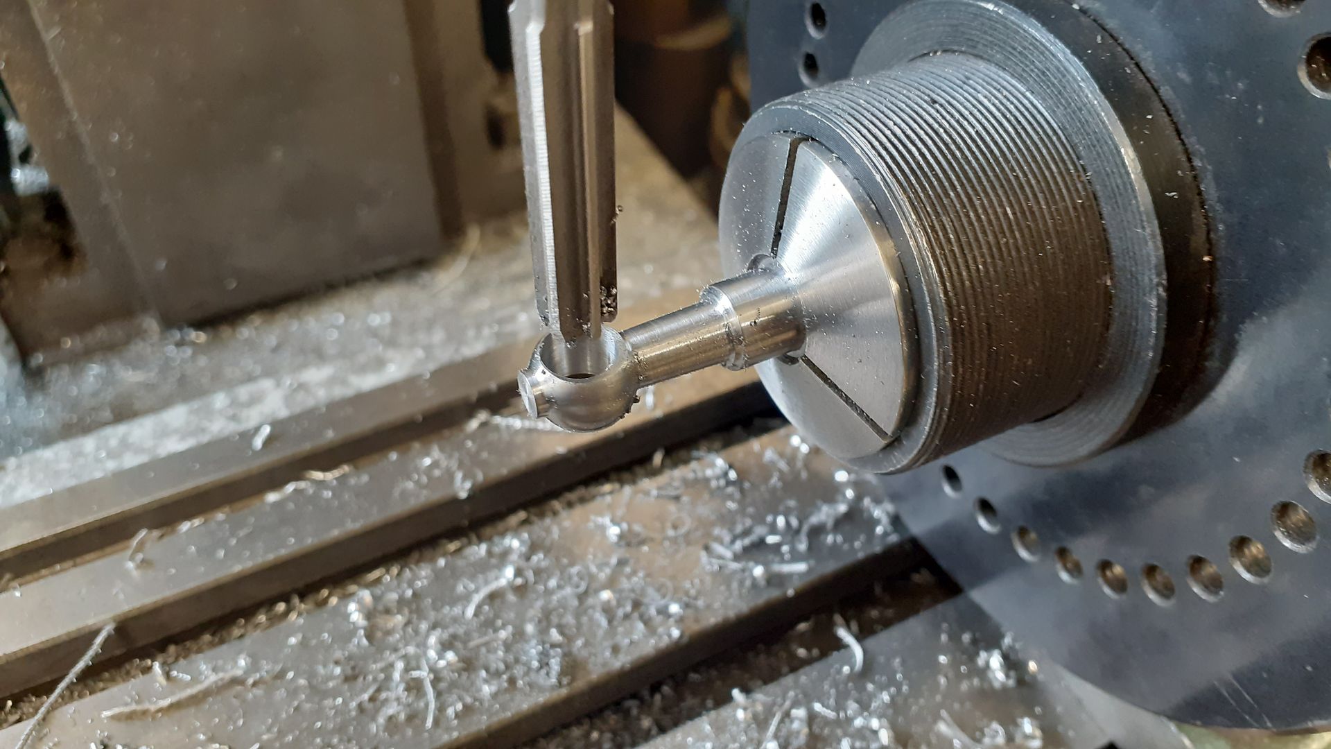
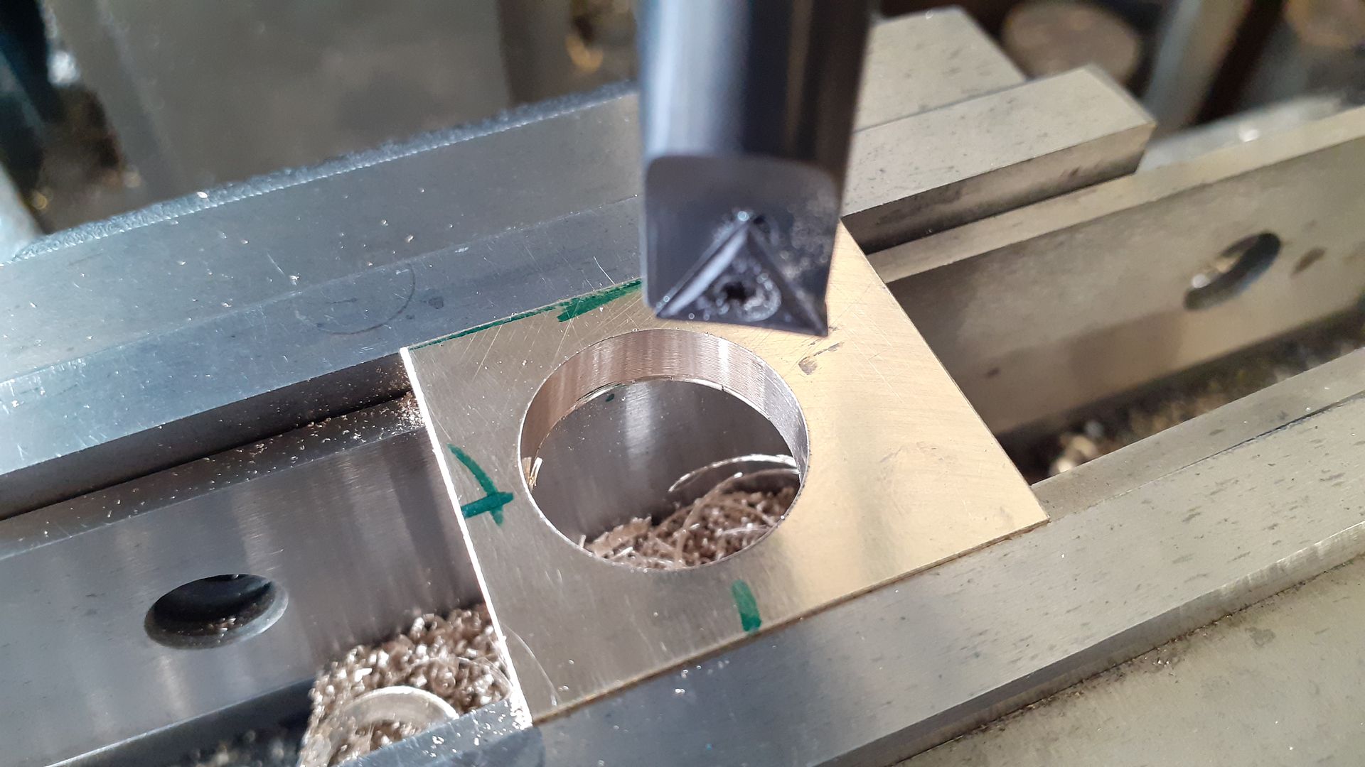
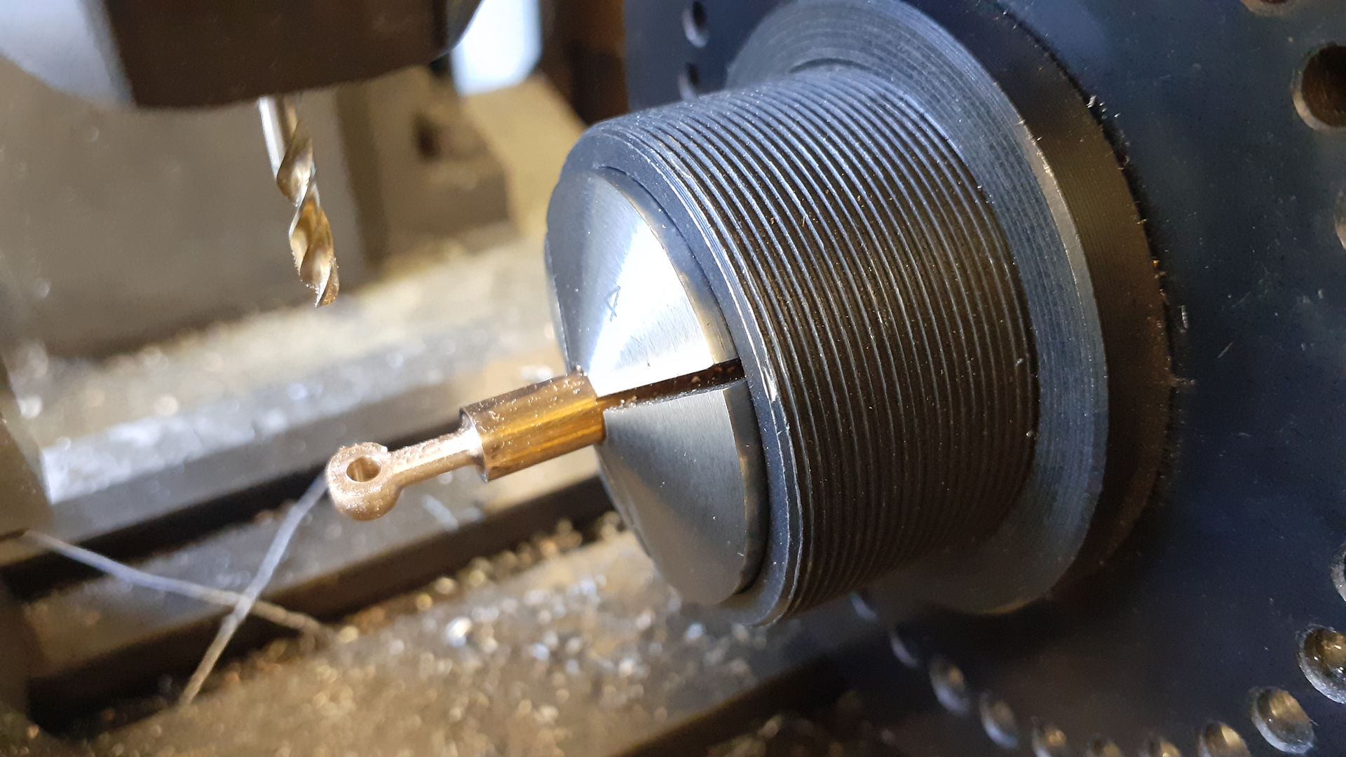
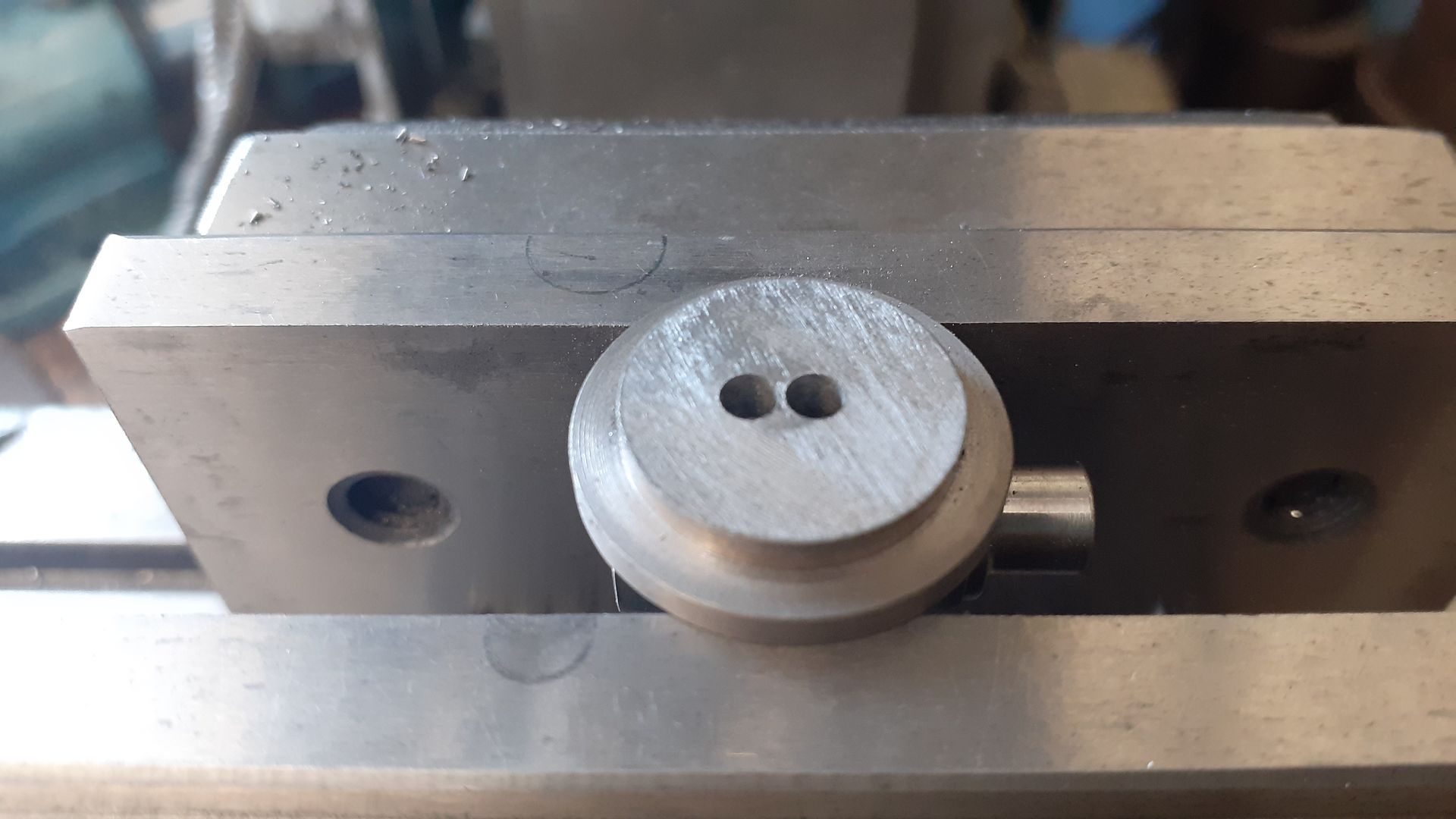
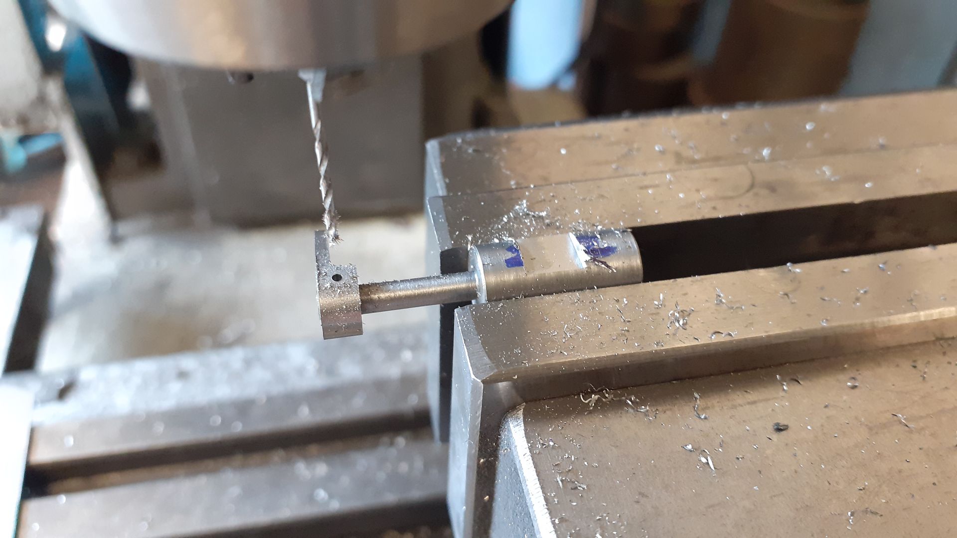
25215 forum posts 3105 photos 1 articles | The piece of thick wall brass tube that I had came out at 22.7mm by the time the chrome plating had been skimmed off so I opted to use a M22 x 0.5mm thread for the gland nut that seals the end of the piston (no rings). I opted to make the female thread first and rather than single point cut it I took the opertunity to have ago a thread milling on the CNC. So an odd bar end of 1" brass was held in a 3-jaw chuck, the end milled flat and then the threading size and smaller clearance hole were bored with the CNC followed by thread milling.
|
| duncan webster | 01/06/2023 23:02:09 |
| 5307 forum posts 83 photos | We once employed a contract draughtsman who had worked on rotary valve IC engines based in the Bolton area. Frank Aspin? He reckoned that when they got the oil consumption down to less than the petrol consumption they thought they were making progress. Unfortunately he was only with us for a few weeks, he probably found something more interesting. Edited By duncan webster on 01/06/2023 23:07:24 |
| Rod Renshaw | 02/06/2023 10:32:07 |
| 438 forum posts 2 photos | The late LBSC used to mention "Treblet " tube in some of his writings. This was a type of brass tube which he thought had been passed through dies 3 times to give a better than usual and more accurate finish, both inside and out. He mentions using it for boiler feed pump barrels and steam whistles, and says that one size fitted nicely inside the next size up. I wonder if this was the type of tube used for the original engine design. Rod |
| Dave Wootton | 02/06/2023 11:53:12 |
| 505 forum posts 99 photos | Duncan's post on rotary valve IC engines and the name Frank Aspin bought back memories from a book " some unusual engines" by L.K.J Setright borrowed from the library years ago. Google search found a really interesting website on Aspin and his engines, lost part of this morning on there! Must have been an interesting character to meet. Very nice work again Jason on another interesting engine, always a pleasure to read. Dave Edited By Dave Wootton on 02/06/2023 11:53:45 |
| JasonB | 03/06/2023 19:54:15 |
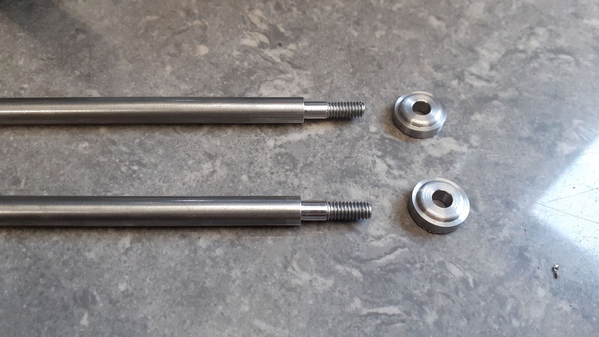
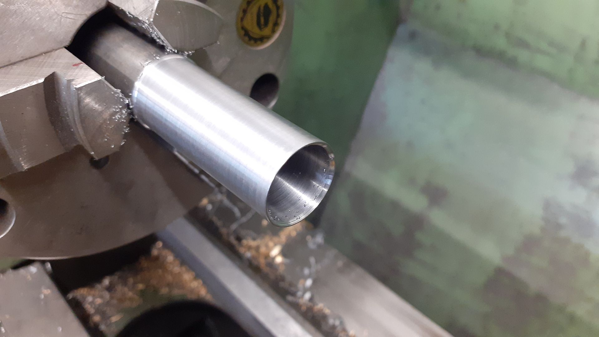
25215 forum posts 3105 photos 1 articles | Rod, the short notes in the original article do mention "mandrel drawn" brass tube so sounds like something similar. At this stage I was enjoying the building so much that I did not take as many photos as I could have done but there is nothing too special about most of the remaining parts. |
| JasonB | 05/06/2023 19:23:25 |
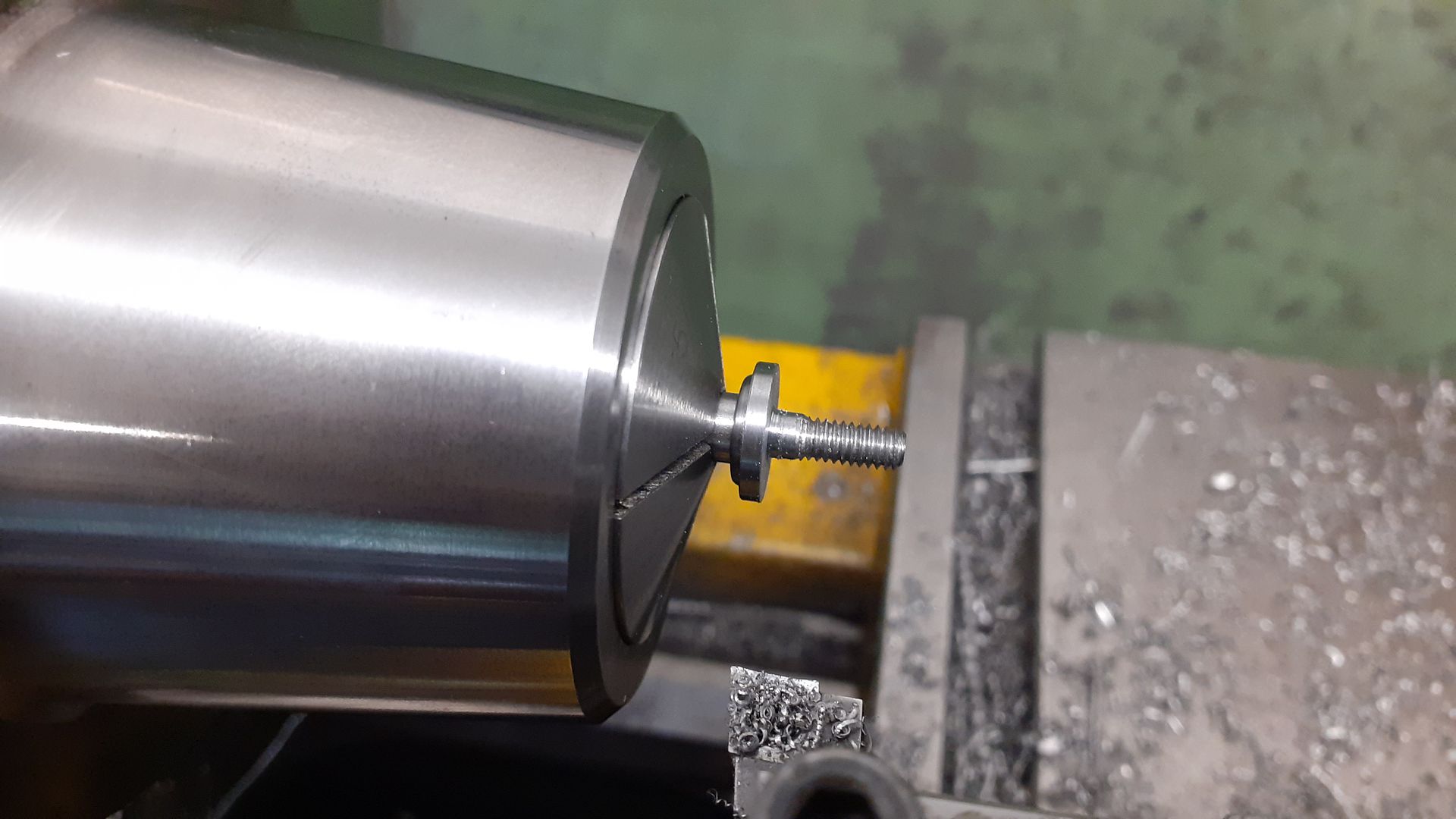
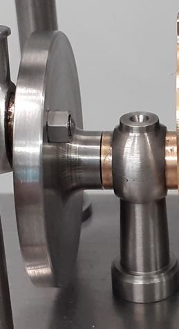
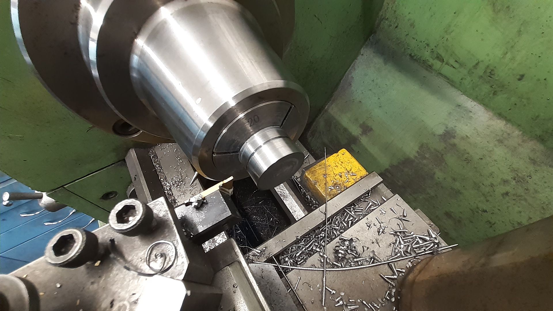
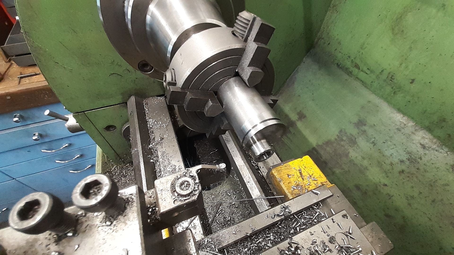
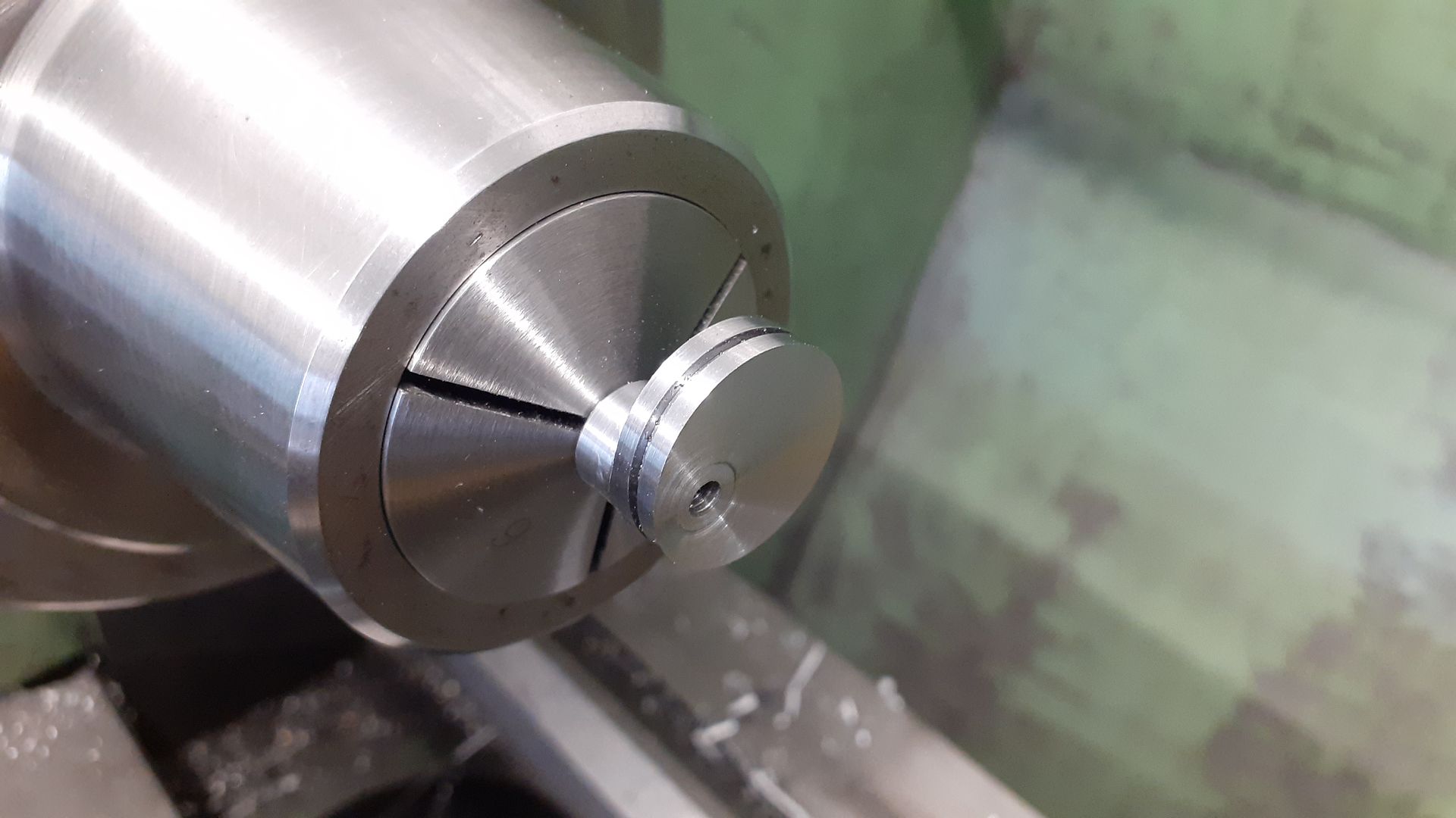
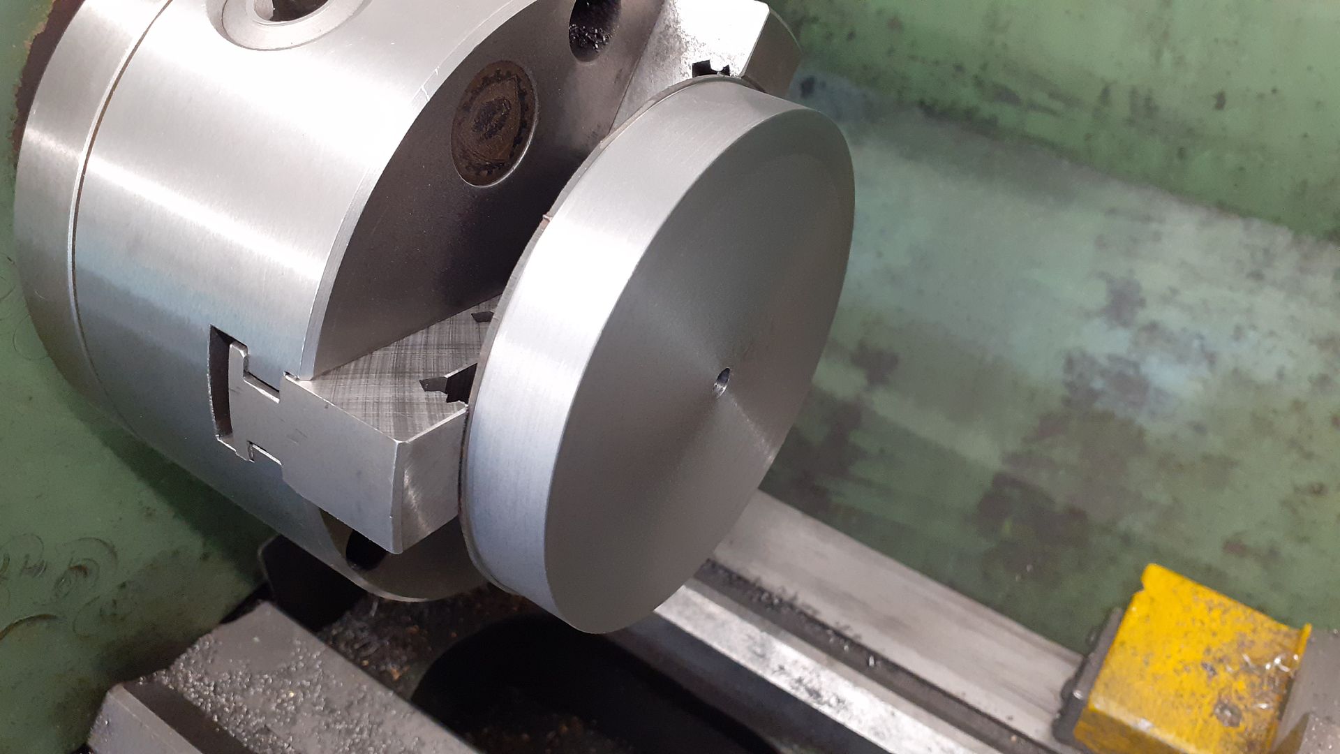
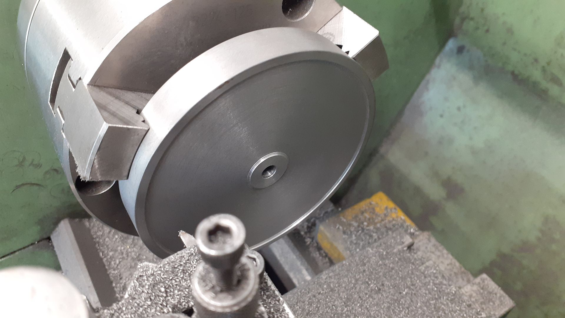
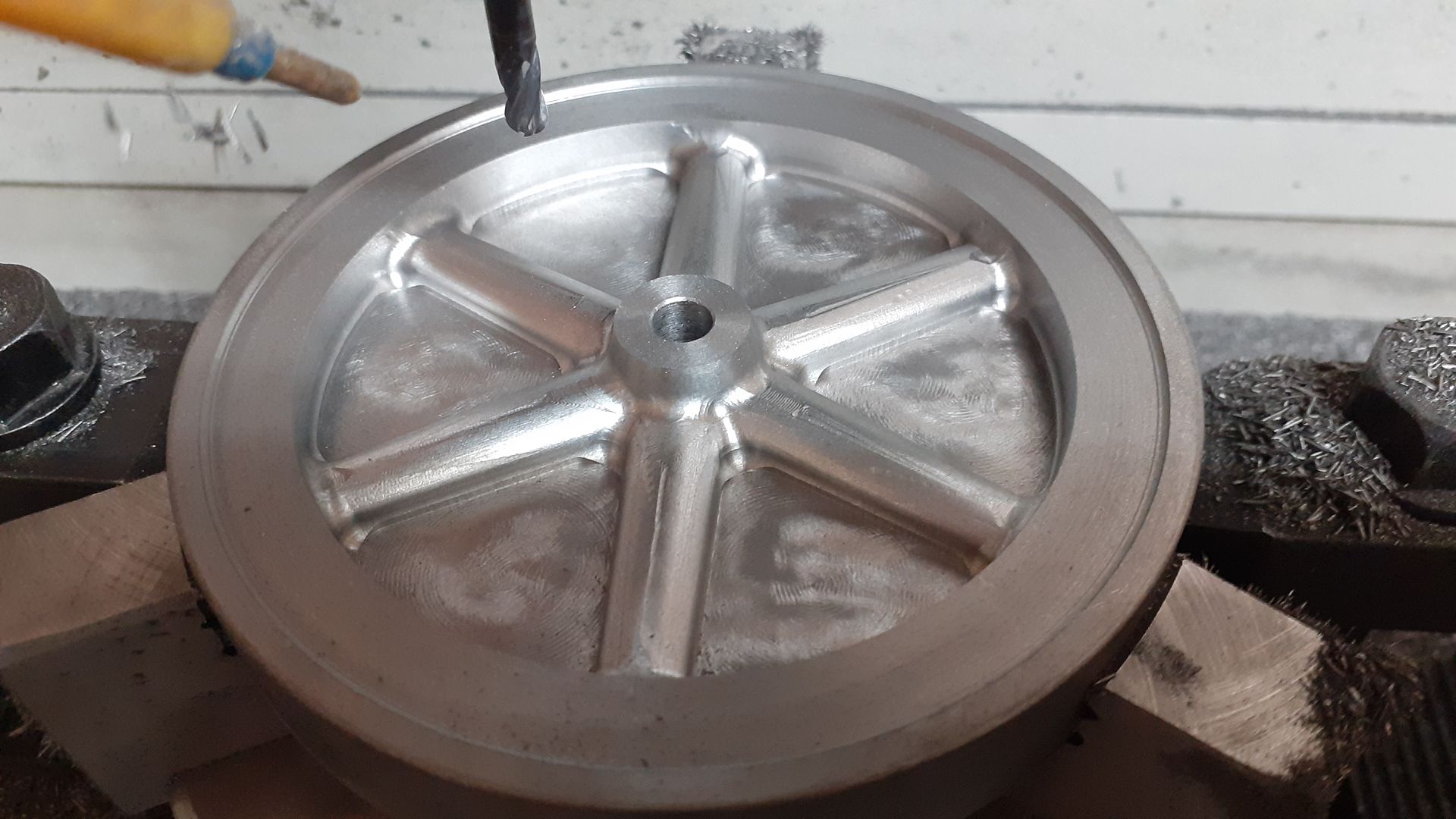
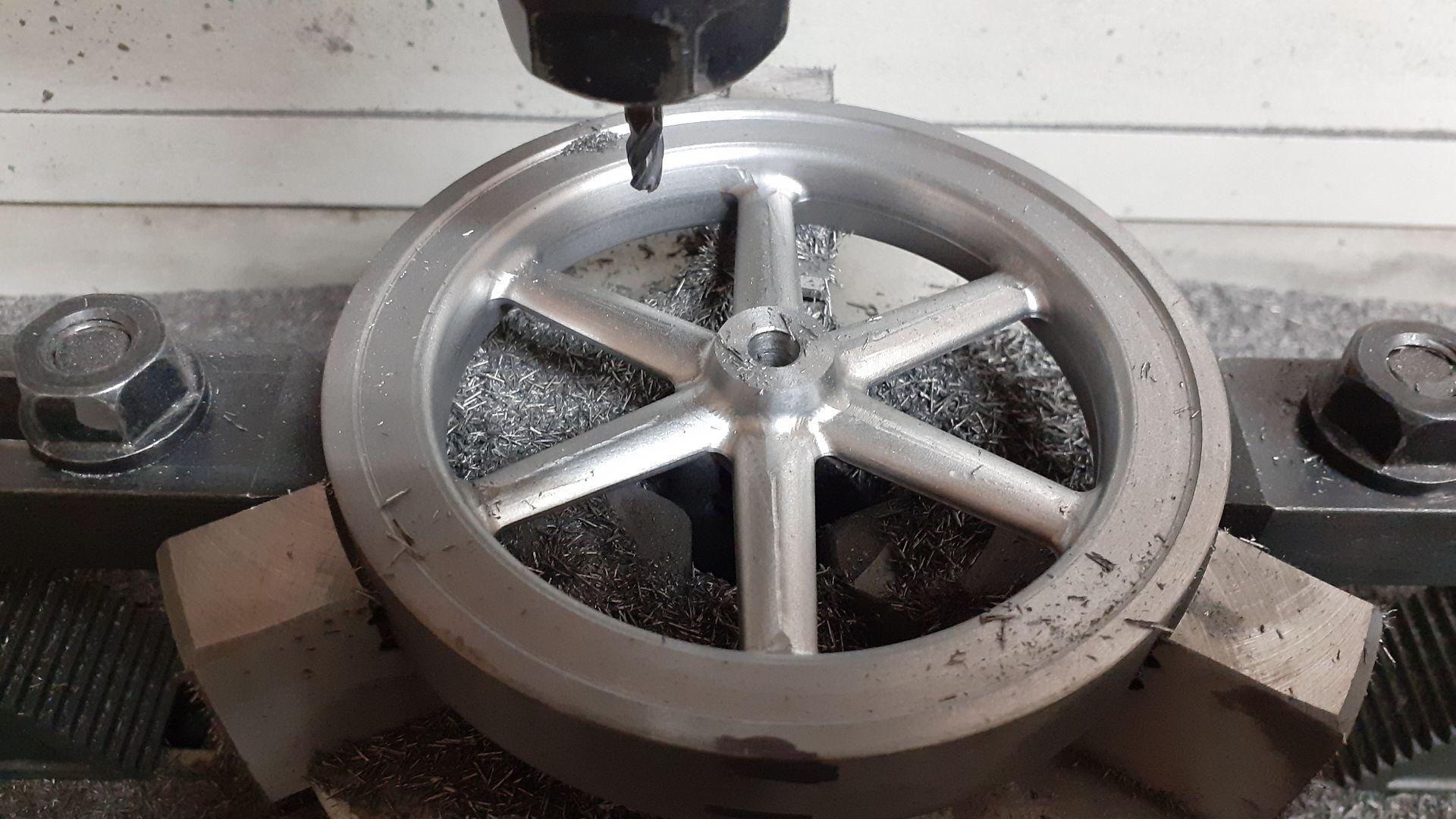
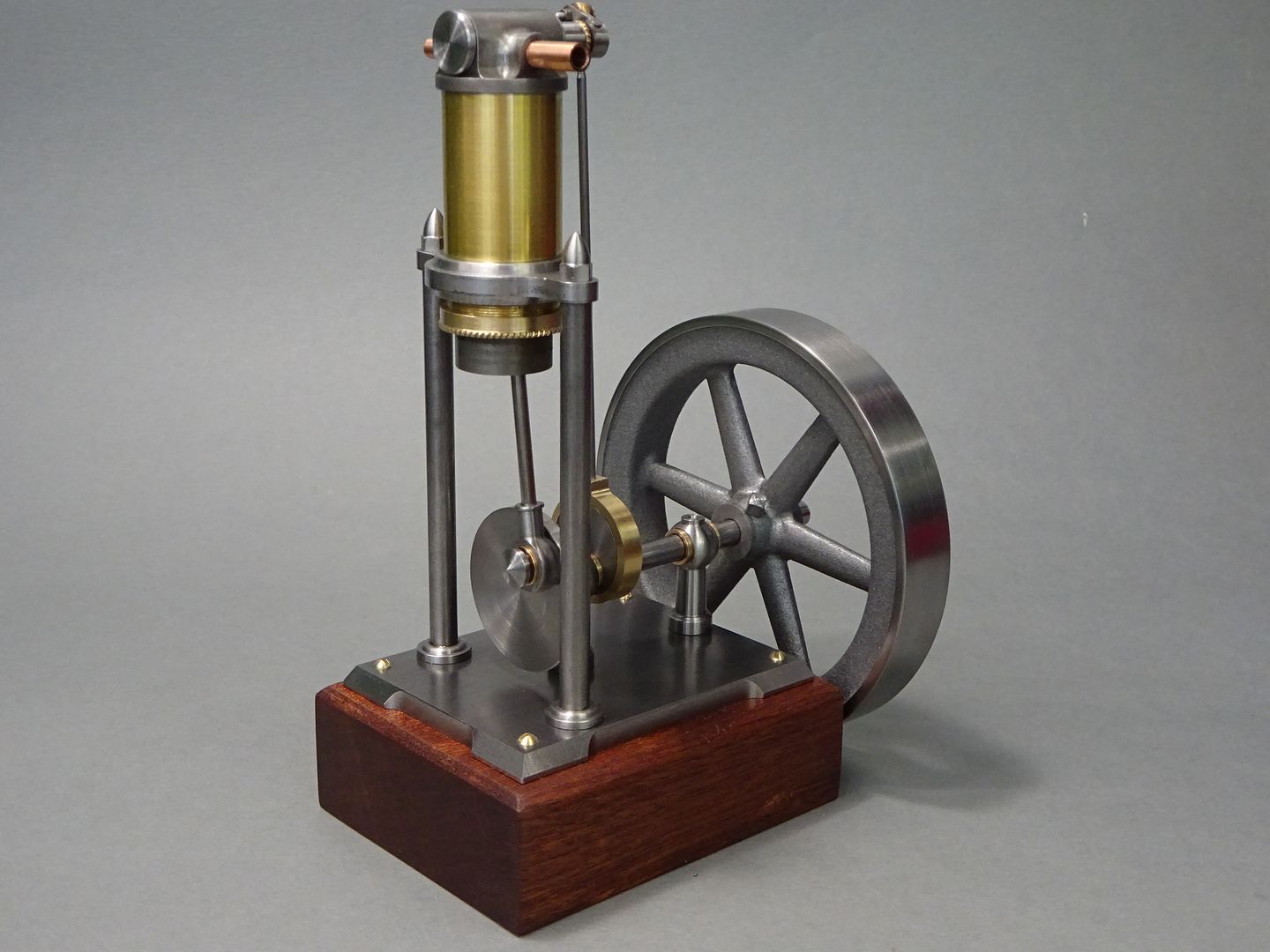
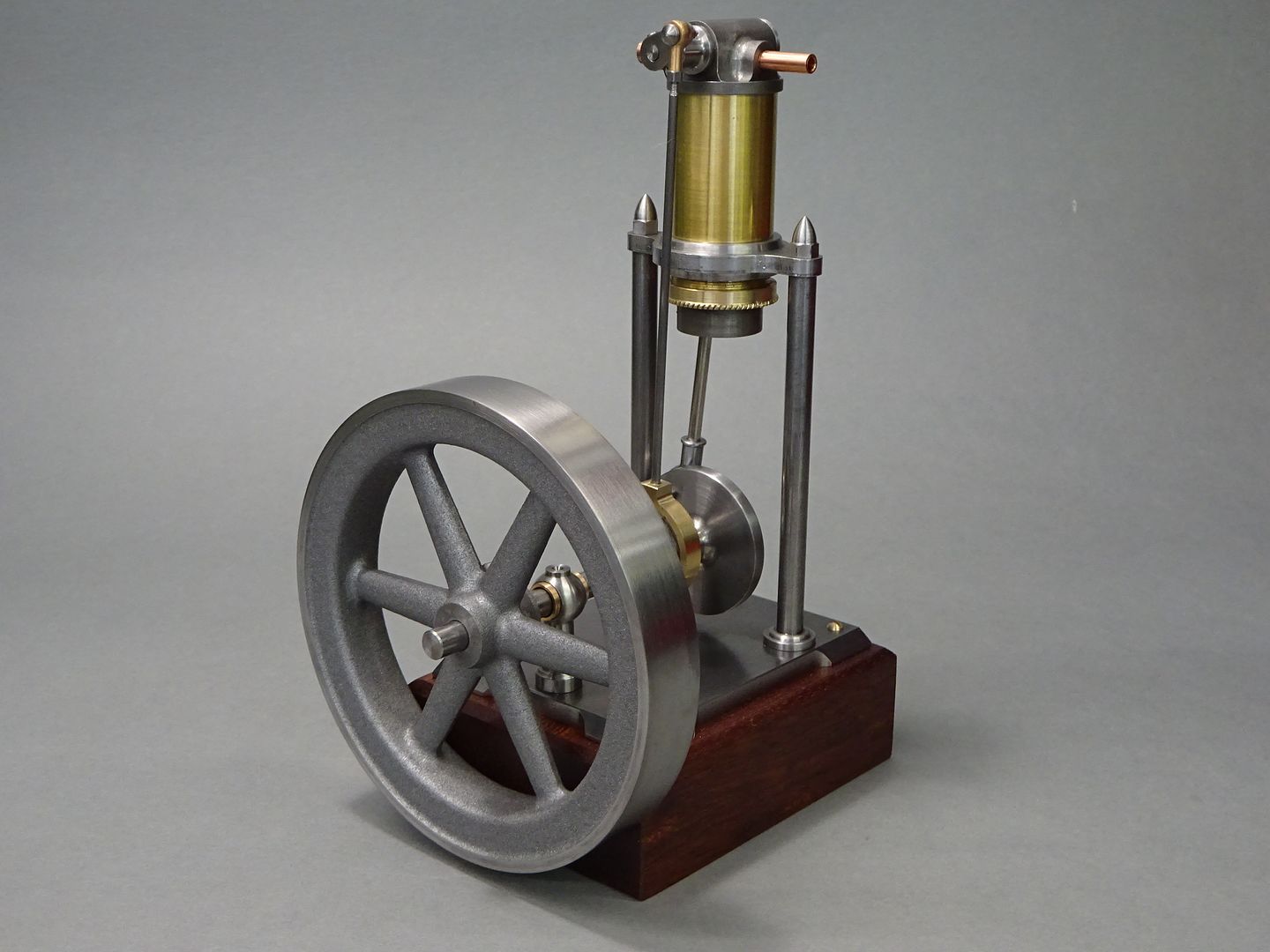
25215 forum posts 3105 photos 1 articles | The engraving shows a flywheel with a fairly deep section rim which no doubt helps get the single acting piston back up to TDC, most castings of the right size seemed a bit lacking in mass so I drew one up and set about making it from a slice of cast iron bar that I had to hand which required holding by the minimal amount while some gentle cuts were taken to clean it up. |
| JasonB | 07/06/2023 20:43:54 |
25215 forum posts 3105 photos 1 articles | Before I continue the build some new information has surfaced which puts the original article at a some what earlier date of 1881 (Thanks Pat) |
| JasonB | 07/06/2023 20:44:47 |
25215 forum posts 3105 photos 1 articles | Well that's another one crossed off the list of "future projects" but the list still seems to be getting longer |
| DiogenesII | 07/06/2023 21:31:55 |
| 859 forum posts 268 photos | That's a nice one - I think you've absolutely nailed the '1880's-scientific' theme there. How many engines do you think you might have made now? |


Please login to post a reply.
Magazine Locator
Want the latest issue of Model Engineer or Model Engineers' Workshop? Use our magazine locator links to find your nearest stockist!
Sign up to our Newsletter
Sign up to our newsletter and get a free digital issue.
You can unsubscribe at anytime. View our privacy policy at www.mortons.co.uk/privacy
Latest Forum Posts
- *Oct 2023: FORUM MIGRATION TIMELINE*
05/10/2023 07:57:11 - Making ER11 collet chuck
05/10/2023 07:56:24 - What did you do today? 2023
05/10/2023 07:25:01 - Orrery
05/10/2023 06:00:41 - Wera hand-tools
05/10/2023 05:47:07 - New member
05/10/2023 04:40:11 - Problems with external pot on at1 vfd
05/10/2023 00:06:32 - Drain plug
04/10/2023 23:36:17 - digi phase converter for 10 machines.....
04/10/2023 23:13:48 - Winter Storage Of Locomotives
04/10/2023 21:02:11 - More Latest Posts...
- View All Topics
Support Our Partners


Shopping Partners
Subscription Offer

Latest "For Sale" Ads
- Reeves** - Rebuilt Royal Scot by Martin Evans
by John Broughton
£300.00 - BRITANNIA 5" GAUGE James Perrier
by Jon Seabright 1
£2,500.00 - Drill Grinder - for restoration
by Nigel Graham 2
£0.00 - WARCO WM18 MILLING MACHINE
by Alex Chudley
£1,200.00 - MYFORD SUPER 7 LATHE
by Alex Chudley
£2,000.00 - More "For Sale" Ads...
Latest "Wanted" Ads
- D1-3 backplate
by Michael Horley
Price Not Specified - fixed steady for a Colchester bantam mark1 800
by George Jervis
Price Not Specified - lbsc pansy
by JACK SIDEBOTHAM
Price Not Specified - Pratt Burnerd multifit chuck key.
by Tim Riome
Price Not Specified - BANDSAW BLADE WELDER
by HUGH
Price Not Specified - More "Wanted" Ads...
Get In Touch!
Do you want to contact the Model Engineer and Model Engineers' Workshop team?
You can contact us by phone, mail or email about the magazines including becoming a contributor, submitting reader's letters or making queries about articles. You can also get in touch about this website, advertising or other general issues.
Click THIS LINK for full contact details.
For subscription issues please see THIS LINK.
Digital Back Issues


Donate

 Register
 Log-in
Model Engineer Magazine
- Percival Marshall
- M.E. History
- LittleLEC
- M.E. Clock

ME Workshop
- An Adcock
- & Shipley
- Horizontal
- Mill

Subscribe Now
- Great savings
- Delivered to your door

Pre-order your copy!
- Delivered to your doorstep!
- Free UK delivery!
All Forum Topics > Stationary engines > Amateurish Engine