Forum sponsored by:

VFD documentation, almost useless
Perils of buying cheap electronic stuff
| Ian P | 12/04/2023 17:33:27 |
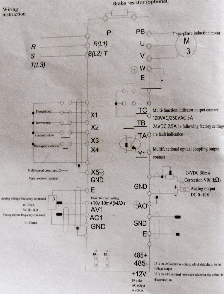
 2747 forum posts 123 photos | I am fully aware of the 'you only get what you pay for' expression relating to purchasing cheap tools and equipment. I recently bought a VFD off Amazon mainly because I needed it quickly and my order placed very late in the afternoon arrived noon the next day. I could have got one from one of the respected well known UK suppliers but I imagine the lateness of me phoning them and the cost of next day delivery (even if it was possible to arrange) would be at a significantly higher cost than the Chinese cheapie now driving my lathe. (It cost £64 for a 2.2KW unit) There is a downside to this bargain VFD, Its not quite plug and play! Documentation accompanying many Chinese manufactured products has for a long time been known to be of poor quality, typically bad translation with spelling mistakes and often serious error and omissions. This VFD came with a small stapled booklet which is virtually all text (well tables of all the parameters etc) plus three diagrams, one of which is this one, Unusually there is not the usual 'quick install' or wiring guide and no views of the physical terminal blocks so the unsuspecting end user is left to their own devices. Being accustomed to VFD's in general I was able to connect the mains input and the three motor phases so was soon able to run the motor with the VFDs own panel. The fun starts when one wants to connect a remote pendant when the supplied diagram is not much help. I was able to work out and get the remote controls operating and have no complaints about my purchase now but I just wanted to point out to anyone on here that its sometimes spending a little more (probably double in my care) to get a recognised brand of product that comes with support.
Edit, apologies for somehow inserting the image twice
Edited By Ian P on 12/04/2023 17:34:49 |
| old mart | 12/04/2023 18:24:15 |
| 4655 forum posts 304 photos | Bad luck with the inverter instructions, you may be able to get help from forum members on wiring and programming it. I have tried for years to get people to do research on these drives before buying them, but low prices are a big factor. Have a look at thes 1.5Kw domestic mains powered inverter from The Inverter Drive Supermarket. Look at the "quick start guide" they include for many of their products, the guide makes it very easy to wire and programme and is worth the higher price.
|
| DC31k | 12/04/2023 19:00:41 |
| 1186 forum posts 11 photos | Interesting diagram. The part that concerns me most is that the motor is shown connected to PB, U and V, with W connected to ground (earth). That is the kind of image that perhaps you should not post online anywhere as if it escapes into the wild, it could have consequences. |
| Mike Poole | 12/04/2023 19:13:13 |
 3676 forum posts 82 photos | The instructions for a VFD are often a pretty heavy read even when well written. As you move further up the range of VFDs they have more and more options to be configured which will require some appreciation of motor theory to make useful choices. They will often run a motor with very few parameters requiring adjustment straight out of the box and will probably default to using the service/commissioning buttons on the front panel. The inputs and outputs are often configurable to interface to manual controls or control systems. Often options are available to operate the drive from the various networks used for control systems and there is plenty of choice, Canbus, modbus, interbus, profinet, devicenet, control net and plenty of others. Some of these network options may be included but an option card will often be required. I notice there is an RS485 connection on the drawing so a datalink of some type is available though the protocol used would need some research. Most of us at home just want a simple button station and pot for speed control so a read up on the options available from the parameters for the l/O ports is required. Mike Edited By Mike Poole on 12/04/2023 19:15:00 |
| Robert Atkinson 2 | 12/04/2023 19:48:05 |
 1891 forum posts 37 photos | Purchasers should remember that VFDs (even the branded ones) are not consumer items. They are not even finished equipment. They are components that are intended to be designed and built into systems or equipment by suitably qualified and experienced persons (SQEP) aka professionals. It is the users responsibility to ensure that they are properly and safely employed. This includes com[lince with relevant regulations. Robert. |
| old mart | 12/04/2023 21:01:40 |
| 4655 forum posts 304 photos | That's correct, Robert, so many people seem to think that the controls on a VFD box are for continuous use, they are not, being only for setting up and programming. This is fine for a unit which is set up and not then touched, as most are. Proper switch and speed control gear separate from the VFD should be added. If somebody has plenty of money, they can buy a fully wired system for as little as double the cost of the parts. |
| Clive Steer | 12/04/2023 22:21:54 |
| 227 forum posts 4 photos | From what I can see it seems the printing has slipped down with regard to the outline and terminals of the VFD outline drawing. So the top right hand 3 terminal should be U, V, W from top down. I can see how this may lead to confusion but the VFD terminal designations do match the common format for other makes. Ian P if you can PM me I can help correct the errors. CS |
| Stuart Bridger | 13/04/2023 08:03:21 |
| 566 forum posts 31 photos | I agree with Clive in that the terminal labelling is all out of line with the functions. Very scary ansd potentially dangerous for those not familiar with such devices. It can be confusing enough undertanding these devices even with a correct diagram. I have to say if quality control lets this slip though in the manual, what else could be wrong? |
| noel shelley | 13/04/2023 09:52:26 |
| 2308 forum posts 33 photos | Like DC3 and clive I was concerned that the terminals and the lettering seemed to have slipped, the one that caught my eye was U,V,W, that should have been the 3 phases to the motor. PB ? Very dangerous ! May be the Mods should remove the diagram lest it be copied or used by someone with NO understanding of electrics and come to harm ? Noel |
| Ian P | 13/04/2023 10:59:48 |
2747 forum posts 123 photos | Clive Stuart DC31K, Noel If we think diagram's P, PB, and the UVW motor terminal connections are badly labelled then what about the mains input! I would say that since the L1, L2 and L3 are only shown (in random positions) on the diagram and not on the VFD own terminals then anyone unfamiliar with this type of product might not even be able to get mains into it. On that basis I doubt leaving this image online can be any sort of risk. As I said earlier, its all up and running although its built in fan is driving me mad! The fan runs all the time the VFD is powered so I intend to add an electronic thermostatic with its sensor bonded to the VFD heatsink. |
Please login to post a reply.
Magazine Locator
Want the latest issue of Model Engineer or Model Engineers' Workshop? Use our magazine locator links to find your nearest stockist!
Sign up to our Newsletter
Sign up to our newsletter and get a free digital issue.
You can unsubscribe at anytime. View our privacy policy at www.mortons.co.uk/privacy
Latest Forum Posts
- *Oct 2023: FORUM MIGRATION TIMELINE*
05/10/2023 07:57:11 - Making ER11 collet chuck
05/10/2023 07:56:24 - What did you do today? 2023
05/10/2023 07:25:01 - Orrery
05/10/2023 06:00:41 - Wera hand-tools
05/10/2023 05:47:07 - New member
05/10/2023 04:40:11 - Problems with external pot on at1 vfd
05/10/2023 00:06:32 - Drain plug
04/10/2023 23:36:17 - digi phase converter for 10 machines.....
04/10/2023 23:13:48 - Winter Storage Of Locomotives
04/10/2023 21:02:11 - More Latest Posts...
- View All Topics
Support Our Partners


Shopping Partners
Subscription Offer

Latest "For Sale" Ads
- Reeves** - Rebuilt Royal Scot by Martin Evans
by John Broughton
£300.00 - BRITANNIA 5" GAUGE James Perrier
by Jon Seabright 1
£2,500.00 - Drill Grinder - for restoration
by Nigel Graham 2
£0.00 - WARCO WM18 MILLING MACHINE
by Alex Chudley
£1,200.00 - MYFORD SUPER 7 LATHE
by Alex Chudley
£2,000.00 - More "For Sale" Ads...
Latest "Wanted" Ads
- D1-3 backplate
by Michael Horley
Price Not Specified - fixed steady for a Colchester bantam mark1 800
by George Jervis
Price Not Specified - lbsc pansy
by JACK SIDEBOTHAM
Price Not Specified - Pratt Burnerd multifit chuck key.
by Tim Riome
Price Not Specified - BANDSAW BLADE WELDER
by HUGH
Price Not Specified - More "Wanted" Ads...
Get In Touch!
Do you want to contact the Model Engineer and Model Engineers' Workshop team?
You can contact us by phone, mail or email about the magazines including becoming a contributor, submitting reader's letters or making queries about articles. You can also get in touch about this website, advertising or other general issues.
Click THIS LINK for full contact details.
For subscription issues please see THIS LINK.
Digital Back Issues


Donate

 Register
 Log-in
Model Engineer Magazine
- Percival Marshall
- M.E. History
- LittleLEC
- M.E. Clock

ME Workshop
- An Adcock
- & Shipley
- Horizontal
- Mill

Subscribe Now
- Great savings
- Delivered to your door

Pre-order your copy!
- Delivered to your doorstep!
- Free UK delivery!
All Forum Topics > Electronics in the Workshop > VFD documentation, almost useless