Forum sponsored by:

Henry Milnes DF4 Lathe Guards
| Darren Reid | 12/11/2022 22:26:10 |
| 7 forum posts 6 photos | Hi all I have recently joined. I own a Henry Milnes DF4 lathe (Denham Junior), I bought the lathe almost 30 years ago when I started college. It belonged to the workshop technicians father who had recently passed away, he estimated that it was probably dated from late 1940s. It has served me well over the years. My problem is that change wheel guards are missing. (Part 4/ 596 and 4/597) It has been like this since I bought it, but now I would like to replace them and give the lathe a overhaul and a new coat of paint. Would anyone with the same lathe be able to draw around the profile of the guards and provide some measurements so I could manufacture them? I did post this on Facebook group machinist museum but unfortunately no response. Thanks Darren II have parts manual but I can't workout how to attach relevant page |
| David George 1 | 13/11/2022 07:41:54 |
 2110 forum posts 565 photos | Hi Darren welcome to the forum. Have you looked on here. http://www.lathes.co.uk/denham/ as it may give you some ideas. David |
| Michael Gilligan | 13/11/2022 07:49:00 |
 23121 forum posts 1360 photos | Posted by Darren Reid on 12/11/2022 22:26:10:
Hi all I have recently joined. I own a Henry Milnes DF4 lathe (Denham Junior), […] II have parts manual but I can't workout how to attach relevant page . Welcome, Darren It would be interesting to see that … so may I encourage you to read this: **LINK** https://www.model-engineer.co.uk/forums/postings.asp?th=103028&p=1 … or at least skim through it until you get the general idea If you are still struggling, just ask MichaelG. |
| Darren Reid | 13/11/2022 09:28:52 |
| 7 forum posts 6 photos | Hi David and Michael Thank you for the welcome and the swift replies Yes David I have been on the "lathes" site which is an excellent resource. Michael hopefully now with your advice I will be able to post photos.
|
| Darren Reid | 13/11/2022 09:29:58 |
| 7 forum posts 6 photos | Belt guard. |
| Ady1 | 13/11/2022 09:52:19 |
 6137 forum posts 893 photos | I think it depends on the lathe Got a couple of piccies here with a full length job
Edited By Ady1 on 13/11/2022 09:56:24 |
| Darren Reid | 13/11/2022 10:05:50 |
| 7 forum posts 6 photos | Hi Ady, thank you for that it dose look similar to my lathe but the headstock is different. I do not know if the guards would be the same ? I have attached a image I found on Google of the guard I need. Edited By Darren Reid on 13/11/2022 10:06:25 |
| Ady1 | 13/11/2022 10:23:09 |
6137 forum posts 893 photos | Your picture looks by far the best one for having a go at fabrication, plus you have your fixed points at the securing screws Make up your inside plate first and then use it as a template for your outside effort would be my route Edited By Ady1 on 13/11/2022 10:29:21 |
| Darren Reid | 13/11/2022 10:40:40 |
| 7 forum posts 6 photos | I may have to go down that route if I don't get any further responses to my post. It will be a case of CAD "cardboard aided design" Ady |
| Hopper | 13/11/2022 10:42:02 |
 7881 forum posts 397 photos | Make a cardboard and tape mock-up based on the pic above and then check it has clearance for the gears and banjo when the largest and smallest gears are fitted throughout. |
| SillyOldDuffer | 13/11/2022 10:47:40 |
| 10668 forum posts 2415 photos | Posted by Darren Reid on 13/11/2022 10:05:50:
Hi Ady, thank you for that it dose look similar to my lathe but the headstock is different. I do not know if the guards would be the same ? I have attached a image I found on Google of the guard I need. ... Welcome to the forum Darren. In the event the measurements aren't forthcoming, perhaps no-one has the same lathe as you, it may be necessary to reverse-engineer a guard from the lathe and photo. It can be done by cutting cardboard sheet to the approximate shape and size, offering it up to the lathe, and progressively trimming to exact size. It would start by identifying the fixing points on the lathe. May take a few goes to get right, but you end up with a cardboard replica that can be dismantled and laid out flat as a template to cut the sheet metal shapes needed to make a real one. As the cardboard replica has to hold together, thinking about it's joints will inform the real build. Sheet metal isn't my thing, but the original guard looks to have been stamped, rolled and maybe crimped from cheap mild steel sheet with pricey equipment you don't have. Several alternatives depending on what you have and depth of pocket. Do you have tools for cutting and forming sheet metal? Do-able with basic tools, but as always the job is easier when the right tools are available. For an exact replica, wooden formers may be necessary. Brass is easy to work and can be soft-soldered but is pricey. Aluminium is cheap, but difficult to solder, so pop-rivets or nuts and bolts. Steel is nicely in the middle, especially if welding is available. If safety is the only concern and looks don't matter, keep it simple - a boxy plate and wire-mesh construct quickly bodged to fit would do. However you do it, it's an interesting challenge. Can you post updates please - be good to see how you get on. It's a learning experience! Dave |
| DC31k | 13/11/2022 10:51:23 |
| 1186 forum posts 11 photos | Posted by Hopper on 13/11/2022 10:42:02:
Make a cardboard and tape mock-up Extending your idea, make some cardboard circles 1" greater in diameter than the biggest change gear used in a particular place. Stick them to the gears with the gears mounted on their shafts and then stick the individual circles together so they maintain their relationship when removed. Lay on the bench and join with tangential lines (or reverse curves - draw around a bucket). Can do the same with the mounting screws. |
| Darren Reid | 13/11/2022 11:11:12 |
| 7 forum posts 6 photos | Hi folks thank you for all the very useful information and suggestions. In response to Dave I just had a quick search on forum and there are a few members with the same lathe. It was also called a Denham Junior, Chris Blight has restored one recently. I have access to sheet metal tools so my plan was to cut out the outer profile with plasma cutter. Then roll the sides to required profile and tack and weld together. I can turn locating sleeves on lathe. I have used mount card in the past to create templates, it is about 1mm thick but holds it shape well and can be hot glue guned together. |
| DC31k | 13/11/2022 13:49:12 |
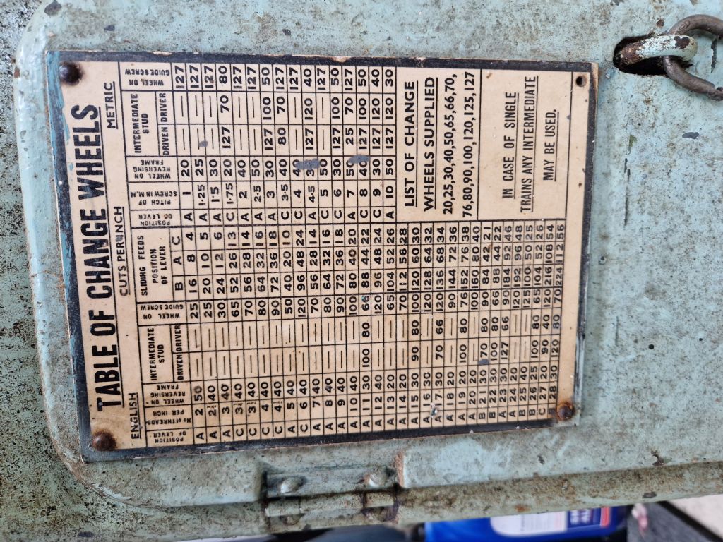
| 1186 forum posts 11 photos | At the risk of flogging a dead horse, you might be able to improve on the original guard. If it is necessary to use a 127t gear on the leadscrew for metric screwcutting (maybe not something that was thought of when the machine was mde), you could make the guard suit that gear. |
| Darren Reid | 13/11/2022 14:59:58 |
| 7 forum posts 6 photos | Hi DC31K another great suggestion, I just checked the change gear table and it was originally designed with metric included with the 127t gear as you stated.
|


Please login to post a reply.
Magazine Locator
Want the latest issue of Model Engineer or Model Engineers' Workshop? Use our magazine locator links to find your nearest stockist!
Sign up to our Newsletter
Sign up to our newsletter and get a free digital issue.
You can unsubscribe at anytime. View our privacy policy at www.mortons.co.uk/privacy
Latest Forum Posts
- hemingway ball turner
04/07/2025 14:40:26 - *Oct 2023: FORUM MIGRATION TIMELINE*
05/10/2023 07:57:11 - Making ER11 collet chuck
05/10/2023 07:56:24 - What did you do today? 2023
05/10/2023 07:25:01 - Orrery
05/10/2023 06:00:41 - Wera hand-tools
05/10/2023 05:47:07 - New member
05/10/2023 04:40:11 - Problems with external pot on at1 vfd
05/10/2023 00:06:32 - Drain plug
04/10/2023 23:36:17 - digi phase converter for 10 machines.....
04/10/2023 23:13:48 - More Latest Posts...
- View All Topics
Support Our Partners


Shopping Partners
Subscription Offer

Latest "For Sale" Ads
- Reeves** - Rebuilt Royal Scot by Martin Evans
by John Broughton
£300.00 - BRITANNIA 5" GAUGE James Perrier
by Jon Seabright 1
£2,500.00 - Drill Grinder - for restoration
by Nigel Graham 2
£0.00 - WARCO WM18 MILLING MACHINE
by Alex Chudley
£1,200.00 - MYFORD SUPER 7 LATHE
by Alex Chudley
£2,000.00 - More "For Sale" Ads...
Latest "Wanted" Ads
- D1-3 backplate
by Michael Horley
Price Not Specified - fixed steady for a Colchester bantam mark1 800
by George Jervis
Price Not Specified - lbsc pansy
by JACK SIDEBOTHAM
Price Not Specified - Pratt Burnerd multifit chuck key.
by Tim Riome
Price Not Specified - BANDSAW BLADE WELDER
by HUGH
Price Not Specified - More "Wanted" Ads...
Get In Touch!
Do you want to contact the Model Engineer and Model Engineers' Workshop team?
You can contact us by phone, mail or email about the magazines including becoming a contributor, submitting reader's letters or making queries about articles. You can also get in touch about this website, advertising or other general issues.
Click THIS LINK for full contact details.
For subscription issues please see THIS LINK.
Digital Back Issues


Donate

 Register
 Log-in
Model Engineer Magazine
- Percival Marshall
- M.E. History
- LittleLEC
- M.E. Clock

ME Workshop
- An Adcock
- & Shipley
- Horizontal
- Mill

Subscribe Now
- Great savings
- Delivered to your door

Pre-order your copy!
- Delivered to your doorstep!
- Free UK delivery!
All Forum Topics > Manual machine tools > Henry Milnes DF4 Lathe Guards