Forum sponsored by:

Sieg SC3 With DRO fitted - Cross Slide Lead screw - Metric or Imperial
| Robin Pulham | 29/12/2021 12:08:28 |
 14 forum posts 14 photos | Good morning all, I have recently bought an Imperial Sieg SC3 lathe which is fitted with DRO's on the cross and compound slides. As part of general tidying up of the machine I wish to take out some/all of the backlash on the cross slide and have watched a couple of videos on YouTube on how I might go about it using a second feed nut. I can buy a spare feed nut from Arc but want to make sure that it will fit my machine before placing the order My question is: Although my machine is imperial, the fact that it's had a DRO kit fitted makes me question whether the leadscrews on the cross and compound slides are in fact now metric? I know that they are replaced as part of fitting the DRO kit available from Chronos. But what I don't know is whether any SC3's were factory fitted with DRO's and if so were the leadscrews on imperial machines replaced with metric to accomodate the DRO's I would really appreciate it if someone could confirm whether this might be the case. As an aside I have put a thread gauge on the leadscrew and it looks to be a 1.25mm pitch with the diameter over the threads as 9.4mm. Which I read as M10 x 1.25. Sadly it being a left hand thread I can't just run a die down it to check. Many thanks for any assistance anyone can offer.
Regards Rob
Edited By Robin Pulham on 29/12/2021 12:08:49 Edited By Robin Pulham on 29/12/2021 12:09:03 |
| Martin Connelly | 29/12/2021 12:51:06 |
 2549 forum posts 235 photos | You have a DRO. Measure the cross slide movement you get with ten turns of the handwheel and divide the result by ten. You will find the pitch of the leadscrew. Ten turns gives a better average than one turn if there is any wear. It should be clear from the pitch if it is metric or inch based. The presence of a DRO makes me think that backlash will not be much of a problem. You are usually pushing a cutting tool into a workpiece on a lathe so backlash does not cause the same sort of problems on a lathe that it causes on mills and a DRO on a mill is usually good enough to take care of the backlash issues. Martin C |
| Robin Pulham | 29/12/2021 13:02:34 |
14 forum posts 14 photos | Thanks Martin, I can see I have much to learn.
Regards Rob |
| JasonB | 29/12/2021 13:15:34 |
 25215 forum posts 3105 photos 1 articles | Posted by Martin Connelly on 29/12/2021 12:51:06:
The presence of a DRO makes me think that backlash will not be much of a problem. If it is the usual SC3 etc DRO than they read the rotation of the handwheel not the actual position of the slide. So backlash will still need to be allowed for but as Martin says it is not really worth worrying about on a lathe. I also have a feeling that although the handwheels had 40 divisions of 0.001" the screws were all 1mm pitch
Edited By JasonB on 29/12/2021 13:25:39 |
| Robin Pulham | 29/12/2021 14:10:49 |
14 forum posts 14 photos | Thanks Jason, Without a definitive answer that would seem to tie in with the compatibility with the metric DRO kit without changing the feed nut. I have it in bits at the minute so I can't try Martin's suggestion but once I have it back together I will give it a whirl. Regards Rob
|
| not done it yet | 29/12/2021 14:44:43 |
| 7517 forum posts 20 photos | You could do like some clever —- on another forum - who thinks that measuring across two threads (one pitch), with a caliper is an accurate way to measure the pitch, but counting as many as your measuring device would require to get a pretty good result should suffice. As it/they is/are the feed screw/s there will be limited teeth available to measure (the lead screw is obviously a lot longer), but you can easily make a ‘dirty’ imprint of the thread on a sheet of paper (or card) to make measurement more precise. If there is 4” of thread it should be possible to discern between a metric or imperial value with reasonable confidence. If you have a decent caliper to measure with, all the better. |
| John Haine | 29/12/2021 16:55:16 |
| 5563 forum posts 322 photos | I'd be surprised if the feed screw pitch was 1.25mm TBH. On the other hand 1.25mm is close to 0.05", which would take 0.1" off the diameter for one turn of the handle. And 9.4mm is a plausible diameter for 3/8". So just as likely to be an imperial screw perhaps. What's the pitch of the main leadscrew? Plenty of advice here on how to measure pitch - how hard can it be when there's a DRO fitted? Why would one change to metric screws when fitting a DRO, as virtually all DROs can be switched between imp and metric? If by using a second nut to take out backlash you mean fitting two nuts to the screw and adjusting the axial position of one to take up the slack, that could be quite hard to arrange without major surgery to the lathe, are you sure that's a risk you want to take? On the X1 mill I had one could adjust the feed nut itself as it had a longitudinal slot and a clamping screw - maybe the lathe has something similar? Also check the play on the screw bearings which will add backlash, and are much easier to adjust especially if you fit ball thrust bearing upgrade. But anyway, backlash on a lathe is not really an issue as long as it isn't really bad as cuts are almost always unidirectional. And the DRO will measure without backlash. If you did have a die that matched the thread, "running it down to check the thread" would probably take off enough metal to permanently increase the backlash! |
| Nigel Graham 2 | 29/12/2021 17:30:15 |
| 3293 forum posts 112 photos | My thoughts exactly: establish the screw leads by the DRO itself and 10 or even 20 turns. Fit as original, too. There may be a case for replacing imperial with metric screws and nuts if you were going to work almost entirely in millimetres on an inch-based lathe, but you'd need also new dials and to replace all three sets to do it properly. Then re-calculate your change-wheel or gearbox tables for screw-cutting. If one is fitted, you'd also need replace the thread-dial with the appropriate metric one. Otherwise the DRO should give you the inch or mm choice of measuring what is actually happening. ..... and never use a die as a thread-gauge, especially on feed- and lead-screws! Use a nut if it's a standard thread. |
| JasonB | 29/12/2021 18:45:45 |
25215 forum posts 3105 photos 1 articles | Minilathe .com confirms a few things. Straight out the factory most Sieg C2/C3 machines have M10 x 1 screws and the 0.001" on the handwheels are really a bit less than that. Exceptions are ones for certain US sellers that have 20tpi screws. Ones with the factory DRO on the handwheels use a 20tpi thread which explains Robins 1.25mm pitch measurent which is actually 1.27mm So if you want to keep the DRO and fiddle about with your nuts you will need to source a 20tpi nut. |
| Neil Wyatt | 29/12/2021 19:11:58 |
 19226 forum posts 749 photos 86 articles | Posted by JasonB on 29/12/2021 13:15:34:
Posted by Martin Connelly on 29/12/2021 12:51:06:
The presence of a DRO makes me think that backlash will not be much of a problem. If it is the usual SC3 etc DRO than they read the rotation of the handwheel not the actual position of the slide. So backlash will still need to be allowed for but as Martin says it is not really worth worrying about on a lathe. I also have a feeling that although the handwheels had 40 divisions of 0.001" the screws were all 1mm pitch
Edited By JasonB on 29/12/2021 13:25:39
I think Jason is correct, at one time Little Machine Shop (IIRC) in the USA were selling Mini lathes with 'Tru-inch' screws. The digital units fit new screws.
In practical terms, the difference with standard 1mm pitch screws is small enough not to be critical over short distances. So if you need to take a cut of (say) 20 thou then half a turn is 0.0197" close enough to 0.020" for practical purposes. As you make bigger steps the errors get bigger. Actually, as it underestimates the distance (by 0.4mm or about 0.016" over an inch) the sensible strategy is to use the scale, then measure the actual size achieved. It will be over by some small amount which can be dialled in without worrying about the error. This is a sensible way to work anyway - approach 'size' then take a small finishing cut. Don't forget (1) when working on a diameter the cut you need is HALF the amount you need to remove and (2) unless you have very sharp tools light cuts may remove less material than you expect (a second or even third pass over the work will usually rectify this). Neil |
| Howard Lewis | 29/12/2021 19:17:26 |
| 7227 forum posts 21 photos | If you want to convert the Cross and Top Slide to Metric, Arc Euro used to do a hit with all the parts (Dials, Leadscrews, Slide ) for about £50 My Chester Conquest mini (With DRO on Cross and Top slides from new ) appears to have 10 tpi leadscrews there, but a 1.5 mm pitch main Leadscrew. The DROs allow you to change the readout from Imperial to Metric, at the touch of a button. It is well worth doing as others have said and measuring the travel over 10 or 20 turns, but take up the backlash first. You will always have some backlash because of clearances. We all live with backlash, even on a brand new machine.. You may well find it a help to read some books on the mini lathe.You will find a set of Zeus Charts to be a useful reference. I still use mine, bought in 1958, almost every time that I go into the workshop. Stan Bray (The founding Editor of MEW ) has written a book on basic lathe work ). Harold Hall, another former Editor, has written a book on Lathework. Dave Fenner (Anothger former Editor ) and Neil Wyatt (Current M E W Editor ) have both written books on the mini lathe. Such books will answer your questions, almost before you feel the need to ask them Also, if you are a newcomer, do not expect a 3 jaw chuck to hold work absolutely concentric. A good one is unlikely to be better than 0.003". And the figure will differ according the diameter being held If you want work to be absolutely concentric, you need a 4 jaw independent chuck, a Magnetic Base and a Dial Test Indicator. The concentricity is then whatever you are prepared to set, or to accept. Such a chuck is invaluable when machining square or irregular work., or if you wish to machine a bore eccentric, deliberately. Find a Model Engineering Club near to you and join. You will learn a lot from fellow members. Finally, learn, and make your mistakes, and how to rectify them, on relatively cheap material, rather than on an expensive casting from a kit! You can learn a lot by by making simple workshop tools. You gain experience, and confidence, and the tools will be useful for years to come. Remember the advice to "Measure twice; cut once" Howard Edited By Howard Lewis on 29/12/2021 19:19:19 |
| John Haine | 29/12/2021 19:29:03 |
| 5563 forum posts 322 photos | Aha! So that was confusing. Didn't mean a "DRO" in the sense we usually use it but one of those turns counting dials. |
| Howard Lewis | 29/12/2021 20:54:13 |
| 7227 forum posts 21 photos | The Chester Conquest Super was, at one time, fitted with digital read out on Cross and Top Slides, allowing Imperial or Metric read out at the touch of a button, rather than the usual "Micrometer" dials. So the operator could apply the cut in which ever unit took their fancy, or was most appropriate. These were not linear DROs., but presumably used angular encoders, programmed to the pitch of the Leadscrew. As such, account would need to taken of any backlash, which you should anyway. Howard.. |
| Robin Pulham | 30/12/2021 10:00:03 |
14 forum posts 14 photos | Thanks for all the replies Gents they are much appreciated and I now have the answer I was looking for plus lots of useful advice as well. To address a a few of the points raised, The reason I thought it might have been a metric lead screw, is when talking to Chronos they advised that their DRO kit had a metric lead screw which is fitted as part of the conversion. I wasn't certain until Jason B confirmed it, that some mini lathes had come with factory fitted DRO's. Having further compared the parts list from Chronos with my parts since starting this thread. I now think that mine is indeed one of the factory fitted examples (the lead screw is in one piece whereas the Chronos kit has it in two parts). I haven't actually tried to test a thread using a die but it seemed (wrongly!!) like it might have given an idea, had I tried it I would have only popped it on the end of the thread I wouldn't have considered running it right down unless there been some thread damage. I have no intention of converting the leadscrews to metric, as has been pointed out, having DRO's fitted makes such an action superfluous. What I am trying to do is make the lathe much more rigid and take out where I can do it sensibly as much backlash as I can. Thanks too to Howard for the reading list, I do have several Howard Hall books and David Fenner's mini lathe book from the Workshop Practice series in my library but I am a great believer in you can't have too many reference book so will add to the library going forward. Thanks again Regards Rob
|
| Robin Pulham | 09/01/2022 20:25:35 |
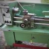
14 forum posts 14 photos | Just to conclude this thread, the leadscrew thread was ultimately 3/8 20tpi a set of taps was ordered from RDG and I now have a prototype of the anti backlash nut/block. I have tried and failed miserably to add a couple of photos
Edited By Robin Pulham on 09/01/2022 20:27:03 Edited By Robin Pulham on 09/01/2022 20:30:50 |
| Pete. | 09/01/2022 20:43:01 |
 910 forum posts 303 photos | Robin, There's a green bar at the top of the page with a picture of a camera labelled Albums, click on that then click on create an album. You're currently not showing any photos added to your profile so I have no idea what you're actually doing to attempt putting photos in. |
| Robin Pulham | 09/01/2022 20:49:09 |
14 forum posts 14 photos | Hi Pete, I was trying to add them via the insert image option next to the camera icon on the tool bar. I will have a look at creating an album.
Many thanks Regards Rob |
| Robin Pulham | 09/01/2022 20:56:02 |
14 forum posts 14 photos | Hopefully that's now sorted thanks to Pete's timely help
It's my intention to do away with the use of the centre grub screw on the feed nut and replace it with shims. I will leave the grub screw in situ to keep the swarf out. I have a thread running on the Gauge O Guild outlining what I am doing in the way of improvements to the SC3. If there is interest I will start a thread here? Thanks again Regards Rob |
| Pete. | 09/01/2022 20:56:21 |
910 forum posts 303 photos | After you've uploaded them to an album, you insert them to a public msg via the camera symbol above the box I'm typing this msg in. Too late you've already managed. Edited By Pete. on 09/01/2022 20:56:57 |
| SillyOldDuffer | 09/01/2022 21:08:25 |
| 10668 forum posts 2415 photos | How to publish photos on the forum described here. Unfortunately you can't drag and drop as some sites allow, but it's easy enough when you know how. Another hint: the forum's own search box top right isn't much cop. The google search midway down the home page is much better. Dave |


Please login to post a reply.
Magazine Locator
Want the latest issue of Model Engineer or Model Engineers' Workshop? Use our magazine locator links to find your nearest stockist!
Sign up to our Newsletter
Sign up to our newsletter and get a free digital issue.
You can unsubscribe at anytime. View our privacy policy at www.mortons.co.uk/privacy
Latest Forum Posts
- *Oct 2023: FORUM MIGRATION TIMELINE*
05/10/2023 07:57:11 - Making ER11 collet chuck
05/10/2023 07:56:24 - What did you do today? 2023
05/10/2023 07:25:01 - Orrery
05/10/2023 06:00:41 - Wera hand-tools
05/10/2023 05:47:07 - New member
05/10/2023 04:40:11 - Problems with external pot on at1 vfd
05/10/2023 00:06:32 - Drain plug
04/10/2023 23:36:17 - digi phase converter for 10 machines.....
04/10/2023 23:13:48 - Winter Storage Of Locomotives
04/10/2023 21:02:11 - More Latest Posts...
- View All Topics
Support Our Partners


Shopping Partners
Subscription Offer

Latest "For Sale" Ads
- Reeves** - Rebuilt Royal Scot by Martin Evans
by John Broughton
£300.00 - BRITANNIA 5" GAUGE James Perrier
by Jon Seabright 1
£2,500.00 - Drill Grinder - for restoration
by Nigel Graham 2
£0.00 - WARCO WM18 MILLING MACHINE
by Alex Chudley
£1,200.00 - MYFORD SUPER 7 LATHE
by Alex Chudley
£2,000.00 - More "For Sale" Ads...
Latest "Wanted" Ads
- D1-3 backplate
by Michael Horley
Price Not Specified - fixed steady for a Colchester bantam mark1 800
by George Jervis
Price Not Specified - lbsc pansy
by JACK SIDEBOTHAM
Price Not Specified - Pratt Burnerd multifit chuck key.
by Tim Riome
Price Not Specified - BANDSAW BLADE WELDER
by HUGH
Price Not Specified - More "Wanted" Ads...
Get In Touch!
Do you want to contact the Model Engineer and Model Engineers' Workshop team?
You can contact us by phone, mail or email about the magazines including becoming a contributor, submitting reader's letters or making queries about articles. You can also get in touch about this website, advertising or other general issues.
Click THIS LINK for full contact details.
For subscription issues please see THIS LINK.
Digital Back Issues


Donate

 Register
 Log-in
Model Engineer Magazine
- Percival Marshall
- M.E. History
- LittleLEC
- M.E. Clock

ME Workshop
- An Adcock
- & Shipley
- Horizontal
- Mill

Subscribe Now
- Great savings
- Delivered to your door

Pre-order your copy!
- Delivered to your doorstep!
- Free UK delivery!
All Forum Topics > Manual machine tools > Sieg SC3 With DRO fitted - Cross Slide Lead screw - Metric or Imperial